Table of Contents
Advertisement
Quick Links
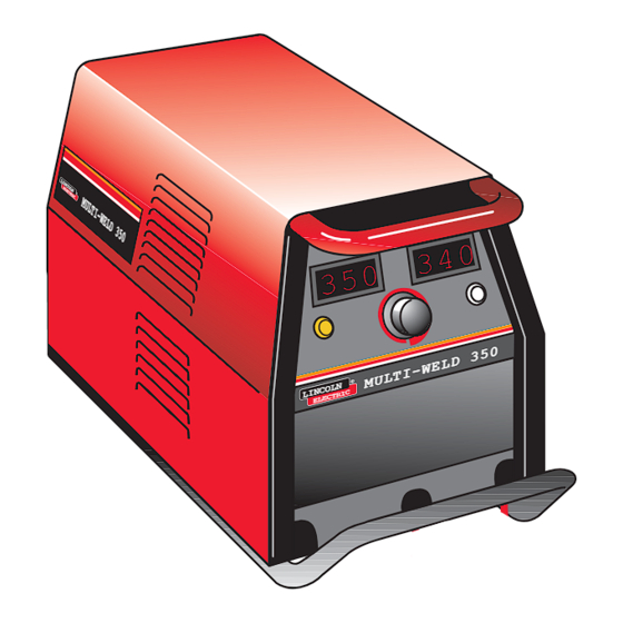
Multi-Weld 350 Arc Converter
For use with machines having Code Numbers:
Safety Depends on You
Lincoln arc welding and cutting
equipment is designed and built
with safety in mind. However,
your overall safety can be
increased by proper installation
... and thoughtful operation on
your part. DO NOT INSTALL,
OPERATE OR REPAIR THIS
EQUIPMENT WITHOUT READ-
ING THIS MANUAL AND THE
SAFETY PRECAUTIONS CON-
TAINED THROUGHOUT. And,
most importantly, think before
you act and be careful.
• Sales and Service through Subsidiaries and Distributors Worldwide •
Cleveland, Ohio 44117-1199 U.S.A. TEL: 216.481.8100 FAX: 216.486.1751 WEB SITE: www.lincolnelectric.com
RETURN TO MAIN MENU
®
10645
10736
11148
11854
OPERATORʼS MANUAL
• World's Leader in Welding and Cutting Products •
Copyright © Lincoln Global Inc.
IM664-C
September, 2011
Advertisement
Table of Contents

Related Manuals for Lincoln Electric Multi-Weld 350 Arc Converter


Summary of Contents for Lincoln Electric Multi-Weld 350 Arc Converter
- Page 1 RETURN TO MAIN MENU IM664-C Multi-Weld 350 Arc Converter ® September, 2011 10645 For use with machines having Code Numbers: 10736 11148 11854 Safety Depends on You Lincoln arc welding and cutting equipment is designed and built with safety in mind. However,...
-
Page 2: California Proposition 65 Warnings
351040, Miami, Florida 33135 or CSA Standard W117.2-1974. A Free copy of “Arc Welding Safety” booklet E205 is available from the Lincoln Electric Company, 22801 St. Clair Avenue, Cleveland, Ohio 44117-1199. BE SURE THAT ALL INSTALLATION, OPERATION, MAINTENANCE AND REPAIR PROCEDURES ARE PERFORMED ONLY BY QUALIFIED INDIVIDUALS. -
Page 3: Electric Shock Can Kill
SAFETY ARC RAYS can burn. ELECTRIC SHOCK can 4.a. Use a shield with the proper filter and cover kill. plates to protect your eyes from sparks and 3.a. The electrode and work (or ground) circuits the rays of the arc when welding or observing are electrically “hot”... - Page 4 SAFETY WELDING and CUTTING CYLINDER may explode SPARKS can if damaged. cause fire or explosion. 7.a. Use only compressed gas cylinders 6.a. Remove fire hazards from the welding area. containing the correct shielding gas for the If this is not possible, cover them to prevent process used and properly operating the welding sparks from starting a fire.
- Page 5 SAFETY zones où lʼon pique le laitier. PRÉCAUTIONS DE SÛRETÉ 6. Eloigner les matériaux inflammables ou les recouvrir afin de Pour votre propre protection lire et observer toutes les instructions prévenir tout risque dʼincendie dû aux étincelles. et les précautions de sûreté specifiques qui parraissent dans ce manuel aussi bien que les précautions de sûreté...
- Page 6 Electric for advice or information about their use of our products. We respond to our customers based on the best information in our posses- sion at that time. Lincoln Electric is not in a position to warrant or guarantee such advice, and assumes no liability, with respect to such infor- mation or advice.
-
Page 7: Table Of Contents
TABLE OF CONTENTS Page Installation........................Section A Technical Specifications .......................A-1 Product Description......................A-2 Recommended Equipment and Processes ................A-3 Multi-System Power Source ..................A-3 Distribution Box ......................A-3 “Pig-Tail” Leads and Connectors ..................A-3 Remote Output Control Options ..................A-4 CV Mode Wire WElding ....................A-4 CC Mode Stick Welding and Gouging................A-4 Quick-Connect “Pig-Tails”... -
Page 8: Installation
INSTALLATION TECHNICAL SPECIFICATIONS - Multi-Weld 350 (K1735-1) ELECTRICAL SPECIFICATIONS AMPS VOLTS (DC+) (DC+) Output Rating @ 50ºC (122°F) Input Rating @ 50ºC (122°F) Max. Input Range 50-113 (Peak) Max. O.C.V. Output Preset Range 30-350 15-40 PHYSICAL DIMENSIONS WIDTH DEPTH NET WEIGHT HEIGHT 11.6 in 10.0 in... -
Page 9: Product Description
INSTALLATION PRODUCT DESCRIPTION only input supply, and provides independent full range The Multi-Weld 350 converter (K1735-1) is part of a control of up to 350A continuous with each converter Multi-Weld system, ideally suited for construction site arc for + polarity stick and wire processes, as well as welding, which uses a single DC power source, as the for arc-air gouging.(See Figure 1). -
Page 10: Recommended Equipment And Processes
(choke) controls and lit displays; including a single such as the Lincoln Electric DC-1000, DC-655 or DC- Power/Mode switch with Input level light, and a 600 set for max. output in CC mode. The power... -
Page 11: Remote Output Control Options
INSTALLATION ATTACHMENT AND ARRANGEMENT OF REMOTE OUTPUT CONTROL OPTIONS "PIG-TAILS" The Multi-Weld 350 is provided with a 6-pin remote To best suit the desired inter-connection of the receptacle to permit use with the 25ft.(7.6 m) K857 or Converters the "pig-tail" cables may be routed into the 100ft.(30.4 m) K857-1 Remote Output Control options, front cable channels, and/or into the back for single or or with the LN-25 equipped with the K444-1 Remote... -
Page 12: Work Connection
INSTALLATION WARNING ELECTRIC SHOCK can kill. Be sure to follow the safety practice to use the female connector on the cable which would normally be electrically "hot" (supply lead) if disconnected when the system is energized, and the male on the normally "cold"... -
Page 13: Inter-Connection Of Converters
INSTALLATION INTER-CONNECTION OF CONVERTERS Power Source (Volts x Amp) capacity > 1.1 x Sum of Convertersʼ (Volts x Amps) arcs The input and electrode cables of the Multi-Weld 350 For Converters (operating at rated output) less than Converters may be inter-connected in a Multi-Weld 200ft. -
Page 14: Connection For Negative Polarity Welding
INSTALLATION Table .1 This connection method will only permit using one Multi-Weld arc on one power source, and cables have Converters Cable Size to be run to the Multi-Weld from both (+) and (-) output on Cable AWG (mm2 ) studs of the power source. -
Page 15: Operation
OPERATION WORK INPUT ELECTRODE Figure 3 The numbered items of Figure 3, above, match the numbered items described below: FRONT PANEL CONTROLS • Only VOLTS digital meter is lit displaying the preset voltage setting These few instruments are basic to the operation and •... -
Page 16: Recessed Panel Controls
OPERATION Average Amps for about 7 seconds after welding RECESSED PANEL CONTROLS stops in CC and CV modes . These instruments are recessed behind a screw • The 7 second memory display is indicated by secured hinged cover panel, and are not typically the displayʼs left-most decimal point blinking, required for normal operator access. -
Page 17: Paralleled Converters
OPERATION PARALLELED CONVERTERS Multi-Weld 350 converters that are paralleled (see Disconnecting the Remoteʼs plug from this recep- INTER-CONNECTION OF CONVERTERS in the tacle automatically transfers output control back INSTALLATION section) must each be set up in the to the panel Output Control (item (2) above). same manner in order to manage the arc current drawn from each: Remote output On/Off switching can also be... -
Page 18: Transporting And Storage Of The Multi-Weld 350
OPERATION TRANSPORTING AND STORAGE Peak Input Voltage Protection OF THE MULTI-WELD 350 The Chopper PC Board will stop switching and inter- rupt the machine output whenever the input voltage CABLE HANDLING across the input capacitors exceeds their 150 volt rat- The input and electrode cables are easily disconnect- ing. -
Page 19: Over-Temperature Shutdown
OPERATION OVER-TEMPERATURE SHUTDOWN The Multi-Weld 350 has a temperature sensing ther- mostat on the input diode heatsink to protect the power components within the Converter from over- heating. If this thermostat temperature exceeds about95°C (203°F) the Converter will electronically shut off the output,and turn on the Thermal Shutdown (yellow) Light until the thermostat is cooled to reset. -
Page 20: Maintenance
MAINTENANCE 3. Holding the unit by the front handles, so the SAFETY PRECAUTIONS back is facing down, shake the loose debris out of the unit. Raking out the heatsink fins may be WARNING necessary for jammed debris. Have qualified personnel do the maintenance work. -
Page 21: Service
MAINTENANCE SERVICE modules which could be simply swapped out at the job site to minimize down time, and so more pro- longed troubleshooting and repair of the module may The Multi-Weld 350 was designed for easy service be done later on the service bench. using quick to replace components, and assembly Figure 5 The above, Figure 5, shows the three assembly modules of the Converter which are covered with the Case... -
Page 22: Troubleshooting
HOW TO USE TROUBLESHOOTING GUIDE WARNING Service and Repair should only be performed by Lincoln Electric Factory Trained Personnel. Unauthorized repairs performed on this equipment may result in danger to the technician and machine operator and will invalidate your factory warranty. For your safety and to avoid Electrical Shock, please observe all safety notes and precautions detailed throughout this manual. - Page 23 TROUBLESHOOTING Observe all Safety Guidelines detailed throughout this manual PROBLEMS POSSIBLE RECOMMENDED (SYMPTOMS) CAUSE COURSE OF ACTION Machine completely dead: 1. Check Input cable connections for Input contactor does not pull in, loose or faulty connection. meters are off. 2. Input voltage may be too low. 3.
- Page 24 TROUBLESHOOTING Observe all Safety Guidelines detailed throughout this manual PROBLEMS POSSIBLE RECOMMENDED (SYMPTOMS) CAUSE COURSE OF ACTION Meter turns on, input contactor 1. The output cable connections may pulls in, thermal light is off. be faulty. 2. The connections at control box plugs, chopper boards plugs, or Analog Control Power Supply PCB may be faulty.
- Page 25 TROUBLESHOOTING Observe all Safety Guidelines detailed throughout this manual PROBLEMS POSSIBLE RECOMMENDED (SYMPTOMS) CAUSE COURSE OF ACTION The meter is not accurate: 1. The Analog Control Power Supply PCB or its connections may be faulty. 2. The Weld Control PCB may be faulty.
- Page 26 TROUBLESHOOTING Observe all Safety Guidelines detailed throughout this manual PROBLEMS POSSIBLE RECOMMENDED (SYMPTOMS) CAUSE COURSE OF ACTION Current changing with arc length 1. Check the CC Slope switch on the in Stick welding: recessed panel, it should be set at Stick/Gauge position for Stick welding.
- Page 27 DIAGRAMS ENHANCED DIAGRAM MULTI-WELD 350...
- Page 28 DIAGRAMS ENHANCED DIAGRAM MULTI-WELD 350...
- Page 29 DIAGRAMS MULTI-WELD 350...
- Page 30 DIAGRAMS MULTI-WELD 350...
- Page 31 Keep your head out of fumes. Turn power off before servicing. Do not operate with panel open or Use ventilation or exhaust to guards off. WARNING remove fumes from breathing zone. Spanish Los humos fuera de la zona de res- Desconectar el cable de ali- No operar con panel abierto o AVISO DE...
- Page 32 Do not touch electrically live parts or Keep flammable materials away. Wear eye, ear and body protection. WARNING electrode with skin or wet clothing. Insulate yourself from work and ground. Spanish No toque las partes o los electrodos Mantenga el material combustible Protéjase los ojos, los oídos y el AVISO DE bajo carga con la piel o ropa moja-...
- Page 33 • World's Leader in Welding and Cutting Products • • Sales and Service through Subsidiaries and Distributors Worldwide • Cleveland, Ohio 44117-1199 U.S.A. TEL: 216.481.8100 FAX: 216.486.1751 WEB SITE: www.lincolnelectric.com...
Need help?
Do you have a question about the Multi-Weld 350 Arc Converter and is the answer not in the manual?
Questions and answers