
Related Manuals for Truper SINCO-10-3


Summary of Contents for Truper SINCO-10-3
- Page 1 Manual Slide compound miter saw Applies for: Code Model 103236 SINCO-10-3 SINCO-10-3 Read this manual thoroughly CAUTION before using the tool.
-
Page 2: Table Of Contents
Parts Unpacking and assembly Keep this manual for future references. Assembly The illustrations in this manual are for reference only. They might be different from the real tool. Adjustments Operation Troubleshooting Maintenance Notes Authorized service centers Warranty policy SINCO-10-3 ENGLISH... -
Page 3: Technical Data
Technical data SINCO-10-3 Code 103236 Description Slide compound miter saw Discs 10” for wood 10” for aluminum Saw blade arbor 5/8” Voltage Frequency 127 V 60 Hz Current 15 A Power 2 1/2 Hp Speed 5 000 RPM Duty cycle 50 minutes work x 20 minutes rest. -
Page 4: General Power Tool Safety Warnings
General power tool safety warnings WARNING! Read carefully all safety warnings and instructions listed below. Failure to comply with any of these warnings may result in electric shock, fire and / or severe damage. Save all warnings and instructions for future references. -
Page 5: Safety Warnings
Safety warnings for the use of a compound miter saw WARNING • ALWAYS keep the power cable away General from the cutting area. The power cable MUST NEVER hang • Do not use the saw for cutting metal, masonry, or concrete. over the workpiece when making the cut. -
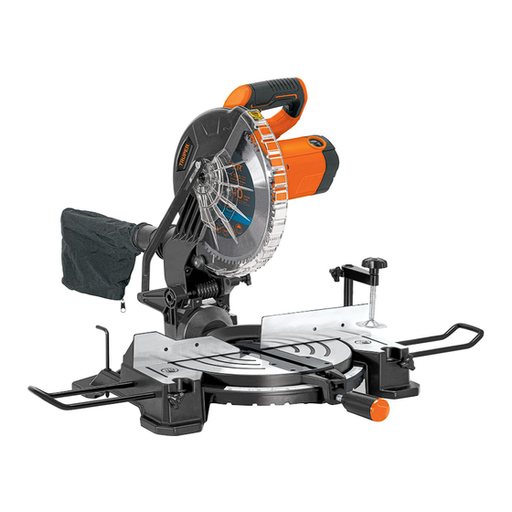
Page 6: Parts
Parts 1. Cutting head. 2. Handle. 3. Trigger switch. 4. Trigger lock. 5. Light switch. 6. Upper blade guard. 7. LED light. 8. Retractable guard. 9. Guard retractor arm. 10. Cutting disc. 11. Shaft lock. 12. Motor. 13. Cutting table. 14. -
Page 7: Unpacking And Assembly
Parts Unpacking and assembly Thanks to strict quality controls, it is highly unlikely that your tool will have any defects or missing parts. In the event of such a case, please visit a Authorized Service Center before using the tool to avoid serious injuries. Workbench mounting •... -
Page 8: Assembly
Assembly Side extension arms • They are useful for supporting workpieces that extend beyond the cutting table area. • To install them on the workbench, loosen the locks on the extension arms (22). • Insert the extension arms (21) on both sides of the table and tighten the locks. - Page 9 Assembly Changing the cutting disc CAUTION • When changing or installing the cutting disc, use protective gloves to prevent injuries. • Disconnect the tool from the electrical power. • Lift the cutting head. • Move the guard retractor arm backward by removing the screw that secures it to the retractable guard with a crosshead screwdriver (A).
-
Page 10: Adjustments
Adjustments Adjustment of the rotary table for miter cuts • To make miter cuts at angles from 45° to -45°, use the rotary table (14). • Press the miter lock lever (19) to release the rotary table. While holding the lever, turn the table using the control knob (18). - Page 11 Adjustments Adjustment of the angle for bevel cuts • Disconnect the tool. • Place the cutting head in the position for bevel cuts at 0°. Ensure that the cutting head stop is in contact with the 0° bevel screw stop (29). •...
-
Page 12: Operation
Operation Start up • To start the saw, move the locking lever (A) inward on the handle, squeeze and hold the trigger switch (3). • To stop the saw, release the switch; doing so activates the automatic brake to stop the saw within seconds. CAUTION •... -
Page 13: Troubleshooting
Troubleshooting Problem Cause Solution The miter saw • Cable disconnected from the power supply. • Connect the power supply cable. doesn´t start. • Electrical issues: blown fuse or tripped circuit • Replace the fuse or reset the circuit breaker. breaker. •... -
Page 14: Notes
Notes ENGLISH... -
Page 15: Authorized Service Centers
In the event of any problem contacting a Authorized Service Center, please see our webpage www.truper.com to get an updated list, or call our toll-free numbers 800 690-6990 or 800-018-7873 to get information about the nearest Service Center. DE TODO PARA LA CONSTRUCCIÓN FIX FERRETERÍAS... -
Page 16: Warranty Policy
It includes the costs of transportation of the product that derive from its fulfillment of its service network. Phone number 800-018-7873. Made in China. Imported by TRUPER, S.A. de C.V. Parque Industrial 1, Parque Industrial Jilotepec, Jilotepec, Edo. de Méx. C.P. 54257, Phone number 761 782 9100.
Need help?
Do you have a question about the SINCO-10-3 and is the answer not in the manual?
Questions and answers