Table of Contents
Advertisement
Quick Links
Advertisement
Table of Contents

Related Manuals for thomann VARYTEC Retro Blinder OCTO 180


Summary of Contents for thomann VARYTEC Retro Blinder OCTO 180
- Page 1 Retro Blinder OCTO 180 Blinder...
- Page 2 Thomann GmbH Hans-Thomann-Straße 1 96138 Burgebrach Germany Telephone: +49 (0) 9546 9223-0 Internet: www.thomann.de 08.05.2024, ID: 588679...
-
Page 3: Table Of Contents
Table of contents Table of contents General information..........................5 1.1 Symbols and signal words....................... 5 Safety instructions............................. 8 Features............................... 12 Installation..............................13 Starting up..............................17 Connections and controls........................19 Operation..............................21 7.1 Starting the device........................... 21 7.2 Operating modes..........................21 7.3 Operating time.......................... - Page 4 Table of contents Cleaning............................... 39 Protecting the environment......................40 Retro Blinder OCTO 180 Blinder...
-
Page 5: General Information
Our products and documentation are subject to a process of continuous development. They are therefore subject to change. Please refer to the latest version of the documentation, which is ready for download under www.thomann.de. 1.1 Symbols and signal words In this section you will find an overview of the meaning of symbols and signal words that are used in this document. - Page 6 General information Signal word Meaning DANGER! This combination of symbol and signal word indicates an immediate dangerous situation that will result in death or serious injury if it is not avoided. WARNING! This combination of symbol and signal word indicates a pos‐ sible dangerous situation that can result in death or serious injury if it is not avoided.
- Page 7 General information Warning signs Type of danger Warning – danger zone. Retro Blinder OCTO 180 Blinder...
-
Page 8: Safety Instructions
Safety instructions Safety instructions Intended use This device is intended for use as an electronic lighting effect by means of LED technology. The device is designed for professional use only and is not suitable for use in households. Use the device only as described in this user manual. - Page 9 Safety instructions DANGER! Danger to life due to electric current! Within the device there are areas where high voltages may be present. Never remove any covers. There are no user-serviceable parts inside. Do not use the device when covers, safety equipment or optical components are missing or damaged. DANGER! Danger to life due to electric current! A short circuit could lead to a fire hazard and risk of death.
- Page 10 Safety instructions NOTICE! Risk of fire due to covered vents and neighbouring heat sources! If the vents of the device are covered or the device is operated in the immediate vicinity of other heat sources, the device can over‐ heat and burst into flames. Never cover the device or the vents. Do not install the device in the immediate vicinity of other heat sources.
- Page 11 Safety instructions NOTICE! Risk of fire by exceeding the maximum current! The device can supply power to other devices of identical design and connected in series. If too many devices are connected, the maximum permitted power consumption can be exceeded, which can cause the device to overheat and burst into flames. Only con‐ nect devices of identical design to the device.
-
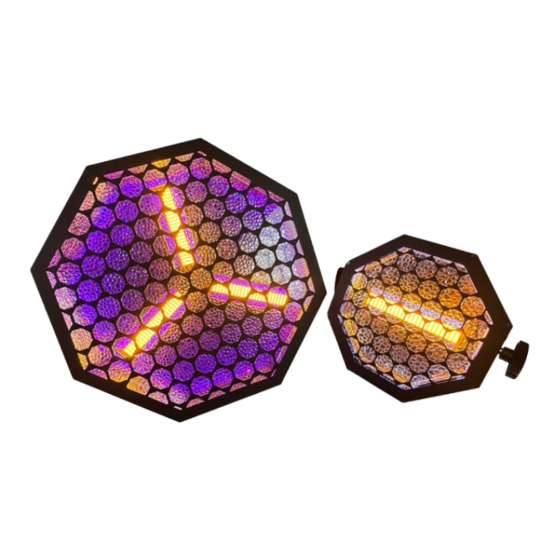
Page 12: Features
Features Features LED blinder with ambient effect in stylish honeycomb shape Ideal as decoration for clubs and bars or for small and medium-sized stages 1 × 80 W warm white COB LED can be used as blinder effect or strobe 64 ×... -
Page 13: Installation
Installation Installation Unpack and check carefully there is no transportation damage before using the unit. Keep the equipment packaging. To fully protect the product against vibration, dust and moisture during transportation or storage use the original packaging or your own packaging material suitable for transport or storage, respectively. - Page 14 Installation NOTICE! Risk of overheating and fire due to inadequate distance and bad ventilation! If the distance between the light source and the illuminated surface is too short or the device is badly ventilated, the device can overheat and cause fires. Make sure that illuminated surfaces are more than 2 m away.
- Page 15 Installation Always work from a stable platform whenever installing, moving or servicing the device. While you do this, the area underneath the device must be cordoned off. The safety cable must be attached to the safety eyelet. Retro Blinder OCTO 180 Blinder...
- Page 16 MENU DOWN ENTER four screws. The connection can be established on all sides of the housing. Depending on the Varytec Retro Blinder OCTO 180 layout, it may be necessary to remove mounting brackets. During assembly, remember that PUSH the device is now heavier.
-
Page 17: Starting Up
Starting up Starting up Create all connections while the device is off. Use the shortest possible high-quality cables for all connections. Take care when running the cables to prevent tripping hazards. Connections in DMX mode Connect the DMX input of the device to the DMX output of a DMX controller or another DMX device. - Page 18 Starting up Connections in ‘Master / When you configure a group of devices in ‘Master / Slave’ mode, the first unit will control the Slave‘ mode others. This feature is especially useful to start a show without much programming. Connect the DMX output of the master unit to the DMX input of the first slave unit.
-
Page 19: Connections And Controls
Connections and controls Connections and controls ö MENU DOWN ENTER Varytec Retro Blinder OCTO 180 PUSH & Retro Blinder OCTO 180 Blinder... - Page 20 Connections and controls 1 Display [MENU] | Activates the main menu for selecting the operating mode. [UP] | Increases the displayed value by one. [DOWN] | Decreases the displayed value by one. [ENTER] | Selects an option of the respective operating mode, confirms the set value 2 Mounting bracket 3 Locking screws for the mounting bracket 4 [DMX IN] | DMX input, designed as XLR panel plug, 3-pin...
-
Page 21: Operation
Operation Operation 7.1 Starting the device Connect the device to the mains to start operation. The device is immediately operational. The set values are retained during a power interruption. 7.2 Operating modes Setting the DMX address This setting is only relevant when the device is controlled via DMX. Press [MENU] repeatedly until ‘Address’... - Page 22 Operation DMX mode Highest possible DMX address 5-channel mode 8-channel mode 27-channel mode Specifying the DMX mode This setting is only relevant when the device is controlled via DMX. Press [MENU] repeatedly until ‘CH Mode’ appears on the display. Confirm with [ENTER]. Use [UP] and [DOWN] to choose between ‘05 CH’...
- Page 23 Operation Automatic mode This operating mode can only be activated when the device is operating in stand-alone mode or as master in a master / slave combination. This setting is only relevant if the device is not controlled via DMX. Press [MENU] repeatedly until ‘Mode’...
- Page 24 Operation To disable automatic mode for the COB LED, use [UP] and [DOWN] to select the ‘Keep’ menu item. Confirm with [ENTER]. ð Automatic mode for the COB LED is deactivated. Manual operation This operating mode can only be activated when the device is operating in stand-alone mode or as master in a master / slave combination.
-
Page 25: Operating Time
Operation 7.3 Operating time Use the ‘Device Time’ menu to call up information about the current runtime of the LEDs. Press [MENU] repeatedly until ‘Device Time’ appears on the display. Confirm with [ENTER]. ð The display shows the total runtime of the LEDs. Retro Blinder OCTO 180 Blinder... -
Page 26: Menu Overview
Operation 7.4 Menu overview Address CH Mode Backlight Mode Device Time 05 CH Auto 08 CH Keep Auto Auto1 Slow 27 CH Quick Auto5 Manual Green Blue White Retro Blinder OCTO 180 Blinder... -
Page 27: Functions In 5-Channel Dmx Mode
Operation 7.5 Functions in 5-channel DMX mode Channel Value Function Ambient LED 0…255 Red intensity (0% to 100%) Ambient LED 0…255 Green intensity (0% to 100%) Ambient LED 0…255 Blue intensity (0% to 100%) Ambient LED 0…255 White intensity (0% to 100%) Strobe LED 0…3 Open... -
Page 28: Functions In 8-Channel Dmx Mode
Operation 7.6 Functions in 8-channel DMX mode Channel Value Function Ambient LED 0…255 Dimmer (0% to 100%) Strobe LED 0…3 Open 4…103 Strobe effect, increasing speed 104…107 Open 108…207 Pulsing strobe effect, increasing speed 208…212 Open 213…251 Random strobe effect, increasing speed 252…255 Open Ambient LED... - Page 29 Operation Channel Value Function 100…255 Automatic mode Ambient LED 0…255 Run speed of automatic mode, increasing speed Retro Blinder OCTO 180 Blinder...
-
Page 30: Functions In 27-Channel Dmx Mode
Operation 7.7 Functions in 27-channel DMX mode Channel Value Function Ambient LED 0…255 Dimmer (0% to 100%) Ambient LED 0…255 White intensity (0% to 100%) Strobe LED 0…3 Open 4…103 Strobe effect, increasing speed 104…107 Open 108…207 Pulsing strobe effect, increasing speed 208…212 Open 213…251... - Page 31 Operation Channel Value Function Ambient LED 0…255 Blue intensity (0% to 100%), segment 2 Ambient LED 0…255 Red intensity (0% to 100%), segment 3 Ambient LED 0…255 Green intensity (0% to 100%), segment 3 Ambient LED 0…255 Blue intensity (0% to 100%), segment 3 Ambient LED 0…255 Red intensity (0% to 100%), segment 4...
- Page 32 Operation Channel Value Function Ambient LED 0…255 Red intensity (0% to 100%), segment 8 Ambient LED 0…255 Green intensity (0% to 100%), segment 8 Ambient LED 0…255 Blue intensity (0% to 100%), segment 8 Retro Blinder OCTO 180 Blinder...
-
Page 33: Technical Specifications
Technical specifications Technical specifications Light source 1 × COB LED, 80 W (strobe) 214 mm 64 × RGB-SMD LED, 0.3 W (ambient) Properties of the COB LED Colour temperature 2700 K Control DMX, buttons and display on the unit Number of DMX channels 5, 8, 27 Input connections Power supply... - Page 34 Technical specifications International Protection IP20 Rating Mounting options Hanging, standing Dimensions (W × H × D) With mounting bracket: 264 mm × 264 mm × 132 mm Without mounting bracket: 214 mm × 214 mm × 132 mm Weight 1.2 kg Ambient conditions Temperature range 0 °C - 40 °C...
- Page 35 Technical specifications Further information Design 1-fold Light source included Variant group Retro blinder Similar design Combination device DMX control Master/slave Remote control Not possible Sound control Display Retro Blinder OCTO 180 Blinder...
-
Page 36: Plug And Connection Assignments
Plug and connection assignments Plug and connection assignments Introduction This chapter will help you select the right cables and plugs to connect your valuable equip‐ ment so that a perfect light experience is guaranteed. Please take our tips, because especially in ‘Sound & Light’ caution is indicated: Even if a plug fits into a socket, the result of an incorrect connection may be a destroyed DMX controller, a short circuit or ‘just’... -
Page 37: Troubleshooting
Troubleshooting Troubleshooting NOTICE! Data transfer errors due to improper wiring! If the DMX connections are wired incorrectly, this can cause errors during the data transfer. Do not connect the DMX input and output to audio devices, e.g. mixers or ampli‐ fiers. - Page 38 DMX interface circuit. 2. Try using another DMX controller. If the procedures recommended above do not succeed, please contact our Service Center. You can find the contact information at www.thomann.de. Retro Blinder OCTO 180 Blinder...
- Page 39 Cleaning Cleaning Optical lenses Clean the optical lenses, that are accessible from the outside, regularly in order to optimize the light output. The frequency of cleaning depends on the operating environment: wet, smoky or particularly dirty surroundings can cause more accumulation of dirt on the optics of the device.
-
Page 40: Protecting The Environment
Protecting the environment Protecting the environment Disposal of the packing material Environmentally friendly materials have been chosen for the packaging. These materials can be sent for normal recycling. Ensure that plastic bags, packaging, etc. are disposed of in the proper manner. Do not dispose of these materials with your normal household waste, but make sure that they are collected for recycling. - Page 41 When disposing of the device, comply with the rules and regulations that apply in your country. You can also return your old device to Thomann GmbH at no charge. Check the current conditions on www.thomann.de.
- Page 42 Notes Retro Blinder OCTO 180 Blinder...
- Page 44 Musikhaus Thomann · Hans-Thomann-Straße 1 · 96138 Burgebrach · Germany · www.thomann.de...
Need help?
Do you have a question about the VARYTEC Retro Blinder OCTO 180 and is the answer not in the manual?
Questions and answers