
Subscribe to Our Youtube Channel
Related Manuals for Fuji Electric ROD-60SB


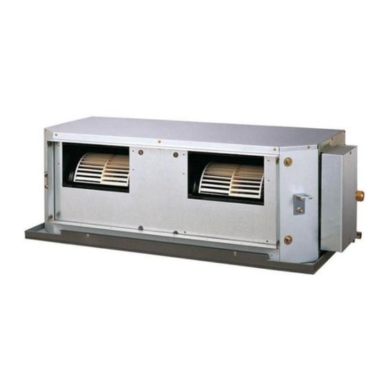
Summary of Contents for Fuji Electric ROD-60SB
-
Page 1: Table Of Contents
SPLIT TYPE AIR CONDITIONER (60Hz) DUCT type Indoor unit Outdoor unit RD-60SC ROD-60SA RD-60SC ROD-60SB RD-60RSC ROD-60RSB CONTENTS SPECIFICATIONS OUTLINE AND DIMENSIONS REFRIGERANT SYSTEM DIAGRAM CIRCUIT DIAGRAM PCB CIRCUIT DIAGRAM DIP SWITCH SETTING ERROR CONTENTS DISASSEMBLY ILLUSTRATION PARTS LIST STANDARD ACCESSORIES... -
Page 2: Specifications
SPECIFICATIONS TYPE Cooling Colling Colling & Heating INDOOR UNIT RD-60SC RD-60SC RD-60RSC OUTDOOR UNIT ROD-60SA ROD-60SB ROD-60RSB COOLING CAPACITY (kW) 14.2 14.2 HEATING CAPACITY (kW) ----- 20.0 ELECTRICAL SPECIFICATIONS POWER SUPPLY FREQUENCY (Hz) COOLIING 12.8 23.5 23.5 RUNNING CURRENT HEATING... -
Page 3: Outline And Dimensions
OUTLINE AND DIMENSIONS (Unit : mm) INDOOR UNIT Models : RD-60SC RD-60RSC 85 mm 1,050 mm 395 mm 1,000 mm 155 mm 1,080 mm 2005.04.01... -
Page 4: Outdoor Unit
OUTDOOR UNIT (Unit : mm) Models : ROD-60SA ROD-60SB ROD-60RSB 2005.04.01... -
Page 5: Refrigerant System Diagram
REFRIGERANT SYSTEM DIAGRAM Models : RD-60SC / ROD-60SA RD-60SC / ROD-60SB OUTDOOR UNIT INDOOR UNIT REFRIGERANT PIPE ACCUMULATOR MUFFLER 19.05mm(3/4") COMPRESSOR CHARGING VALVE EVAPORATOR CAPILLARY TUBE DRYER REFRIGERANT PIPE CHARGING 9.52mm(3/8") VALVE Models : RD-60RSC / ROD-60RSB OUTDOOR UNIT INDOOR UNIT REFRIGERANT PIPE 19.05mm(3/4") -
Page 6: Circuit Diagram
CIRCUIT DIAGRAM Model : RD-60SC Model : RD-60RSC 2005.04.01... - Page 7 Model : ROD-60SA Model : ROD-60SB 2005.04.01...
- Page 8 Model : ROD-60RSB 2005.04.01...
- Page 9 INDOOR PCB CIRCUIT DIAGRAM Model : RD-60SC CONTROLLER PCB ASSEMBLY ( MAIN PCB ) EZ-00304WSE-C TRANS. SECONDARY CN105 R15 - R17 B04B-PASK-1 CN104 B2B-XARK-1-A 5V 12V 14V 10K <1/10W> x 3 DC SUPPLY WHITE 10K <1/10W> x 3 UL1430 AWG22 UL1430 AWG26 GRAY R18 - R20...
- Page 10 CONTROLLER PCB ASSEMBLY ( MAIN PCB ) Model : RD-60RSC EZ-003SHSE-C CN105 R15 - R17 5V 12V 14V TRANS. (SEC. ) DC SUPPLY B04B-PASK-1 10K <1/10W> x 3 CN104 B2B-XARK-1-A <WHT> <RED> UL1430 AWG22 UL1430 AWG26 <GRY> R18 - R20 UL1430 AWG22 UL1430 AWG26 <GRY>...
- Page 11 OUTDOOR PCB CIRCUIT DIAGRAM CONTROLLER PCB ASSEMBLY ( MAIN PCB ) CN11 EZ-0038HUE-C B6B-XASK-1-A WHITE Model : ROD-60RSB CN11-1 UL1430 AWG24 CN11-2 UL1430 AWG24 BROWN VDD1 VDD0 I C4-7 uPA2003 R59 10 <1/10W> CN11-3 UL1430 AWG24 BLUE D3SB60 AVREF I C9 EEV-A AVDD EXPANSION VALVE-A...
-
Page 12: Dip Switch Setting
DIP-SWITCH SETTING Indoor Unit SW state Detail Out of Use DIP-Switch SW state Detail Remote sensor setting Ceiling setting(+4 Room setting(0 Edge Pulse Control input setting DIP-Switch Validity Invalidity Auto restart setting SW state Detail Connect Disconnect Out Of Use Residencial Commercial Commercial mode setting... -
Page 13: Error Display
ER R OR D ISP LA Y Error code Error contents CAUTION Float switch operated Supply power to the crankcase heater for at least 12 hours before the start of operation in winter. Outdoor temperature sensor open (1) Stop the air conditioner operation. Outdoor temperature sensor short-circuited (2) Press the master control button and the fan control button simultaneously for 2 seconds or more to start the test run. -
Page 14: Disassembly Illustration
DISASSEMBLY ILLUSTRATION Models : RD-60SC RD-60RSC 2005.04.01... - Page 15 Models : RD-60SC RD-60RSC 824-3 815-2 815-1 824-5 2005.04.01...
- Page 16 Models : ROD-60SA ROD-60SB ROD-60RSB 2005.04.01...
- Page 17 Models : ROD-60SA ROD-60SB 2005.04.01...
- Page 18 Model : ROD-60RSB 2005.04.01...
- Page 19 Models : ROD-60SA ROD-60SB 2005.04.01...
- Page 20 Model : ROD-60RSB 2005.04.01...
-
Page 21: Parts List
PARTS LIST INDOOR UNIT Parts No. Ord. Ref. Description Q'ty RD-60SC RD-60RSC DRAIN PAN ASSY PRINTED 9372047026 9372047026 CAPACITOR,PLASTIC 9704436146 9704436146 CAPACITOR CLAMP 9308114006 9308114006 SIROCCO FAN 9372059012 9372059012 CASING B 9372058015 9372058015 CASING A 9372057018 9372057018 MOTOR, INDUCT 9601820017 9601820017 KIT (PANEL FRONT SUB ASSY) 9372637012... -
Page 22: Outdoor Unit
OUTDOOR UNIT Part No. Part No. Ref. Ord. Ref. Ord. Description Description Q’ty Q’ty ROD-60SA ROD-60SB ROD-60SA ROD-60SB Fan Cover 9352159015 9352159015 Muffler 9368082000 9368082000 Emblem-Rear 9361328006 9361328006 333-2 Accumulator(B) 9362425001 9362425001 Cabinet-A, Painted 9352146015 9352146015 Suction Pipe-B 9352287008 9352287008... - Page 23 OUTDOOR UNIT Part No. Part No. Ref. Ord. Ref. Ord. Description Description Q’ty Q’ty ROD-RSB ROD-RSB Fan Cover 9352159015 344-2 4-Way Valve 9353532008 Emblem-Rear 9361328006 Pressure Switch 9704045003 Cabinet-A, Painted 9352146015 Grip 9352157004 Cabinet-C, Painted 9352149016 Locking Spacer 313209391506 Cabinet-B, Painted 9352147012 Clamp No.
-
Page 24: Standard Accessories
STANDARD ACCESSORIES INDOOR UNIT ACCESSORIES OUTDOOR UNIT ACCESSORIES Name and Shape Q’ty Application Name and Shape Q’ty Application Power cap Special nut A For power supply cord (large flange) installation For suspending the indoor unit from ceiling Auxiliary pipe assembly Special nut B For wiring conduit (small flange) - Page 25 0501G2750...
Need help?
Do you have a question about the ROD-60SB and is the answer not in the manual?
Questions and answers