Advertisement
Table of Contents
- 1 Table of Contents
- 2 Room Air Conditioner
- 3 Wall Mounted Type
- 4 Indoor Unit
- 5 Outdoor Unit
- 6 Specifications
- 7 Dimensions
- 8 Refrigerant System Diagram
- 9 Circuit Diagram
- 10 Indoor Pcb Circuit Diagram
- 11 Outdoor Pcb Circuit Diagram
- 12 Disassembly Illustration
- 13 Parts List
- 14 Cover (Switch)
- 15 Accessories
- Download this manual
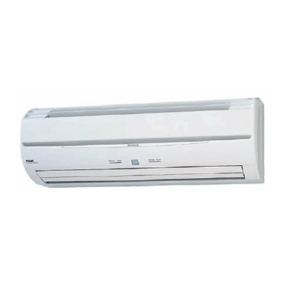
SPLIT TYPE
ROOM AIR CONDITIONER
WALL MOUNTED TYPE
Indoor unit
Outdoor unit
RSA12LCC
ROR12LCC
CONTENTS
. . . . . . . . . . . . . . . . . .
. . . . . . . . . . . . . . . . . . . . .
. . . . . . . . . . . . . . . . .
. . . . . . . . . . . . . . . .
ERROR CONTENTS
. . . . . . . . . . . . . . . . . . . . . .
. . . . . . . . . . . . . . . . . . .
1
2
. . . .
3
4
. . . . . .
5
. . . .
6
8
. . . . . . .
9
12
14
Advertisement
Table of Contents

Summary of Contents for Fuji Electric RSA12LCC
-
Page 1: Table Of Contents
SPLIT TYPE ROOM AIR CONDITIONER WALL MOUNTED TYPE Indoor unit Outdoor unit RSA12LCC ROR12LCC CONTENTS ....SPECIFICATIONS ..... -
Page 2: Specifications
SPECIFICATIONS ELECTRICAL DATA COMPRESSOR AND REFRIGERANT Hermetic type, Cool & Heat Inverter TYPE 4 pole, 3 phase, INDOOR UNIT RSA12LCC TYPE DC inverter motor, OUTDOOR UNIT ROR12LCC Rotary COOLING CAPACITY 3.50 kW DISCRIMINATION DA89X1C - 20FZ HEATING CAPACITY 4.80 kW... -
Page 3: Dimensions
DIMENSIONS Models : RSA12LCC / ROR12LCC (unit : mm) 2006.01.24... -
Page 4: Refrigerant System Diagram
REFRIGERANT SYSTEM DIAGRAM Models : RSA12LCC / ROR12LCC Heat exchanger 3-Way ( INDOOR ) valve Muffler 2-Way valve 4-Way valve Strainer Expansion valve Heat exchanger Strainer ( OUTDOOR ) Cooling Heating Refrigerant pipe diameter Liquid : 1/4" (6.35 mm) Gas : 3/8" (9.52 mm) -
Page 5: Circuit Diagram
CIRCUIT DIAGRAM Models : RSA12LCC / ROR12LCC INDOOR UNIT Display Board Fan Motor Derminal Board BLACK CONTROLLER PCB Controller PCB BROWN GREEN / YELLOW Thermistor Thermistor Stepping (room temp.) (pipe temp.) Motor OUTDOOR UNIT PCB (MAIN) Reactor Reactor Compressor R(U) -
Page 6: Indoor Pcb Circuit Diagram
INDOOR PCB CIRCUIT DIAGRAM Model : RSA12LCC Jumper wire configurations Switch Function ON/Linked OFF/Open TERMINAL BOARD POWER SOURCE BLUE 230V Custom code 50Hz GREEN / YELLOW Auto restart enable disable I C 1 BLACK uPD780024ASGB-X70-8ET-A CONTROLLER PCB ASSEMBLY ( MAIN PCB ) -
Page 7: Outdoor Pcb Circuit Diagram
OUTDOOR PCB CIRCUIT DIAGRAM Model : ROR12LCC INVERTER ASSEMBLY EZ-0054HUE EMI FILTER AC230V ZCAT2132-1130 F201 50Hz 20A - 250V UL1015 AWG14 UL1015 AWG14 BLACK BLACK W1 B UL1015 AWG14 SERIAL WHITE W2 B REACTOR EMI FILTER 15MH 10A UL1015 AWG20 TERMINAL BOARD UL3271 AWG16 W4 B... - Page 8 CONTROLLER PCB ASSEMBLY K05CM-0500HUE-C1 Model : ROR12LCC F100 15A-250V DC V U V W REACTOR R200 39 L300 D102 <1/2W> ELC0607RA R400 BET 3.15A-250V 1NH42 AC230V W7 W8 W9 U1JU44 x 3 0.01/ R401 R103 50Hz 250V D200 D201 D202 D100 R402 R104...
-
Page 9: Disassembly Illustration
DISASSEMBLY ILLUSTRATION Model : RSA12LCC 2005.02.07... - Page 10 Model : RSA12LCC 2006.02.07...
- Page 11 Model : ROR12LCC 2006.02.07...
-
Page 12: Parts List
PARTS LIST INDOOR UNIT Part No. Ref. Ord. Description Q'ty RSA12LCC Air Filter 9309997011 Filter (Electric) 9312153015 Filter (ION) 9311925033 Holder (Filter) 9306602017 Clamper (Grille) 9306755010 Front Panel Total Assy 9313130114 Intake Grille Assy 9313131074 Gear-A 9309994003 Casing Assy 9311354079... -
Page 13: Cover (Switch)
OUTDOOR UNIT Part No. Ref. Ord. Description Q'ty ROR12LCC Fuse Holder 0501454012 Fuse 0600382018 Thermister Holder Pipe 313714262805 Thermistor Spring-A 313728262708 Thermistor Spring 9300089012 Terminal 9306489038 Cord Clamp 9307271014 Cover (Case) 9309913011 Bracket Valve 9310229026 Cover (Switch) 9310979013 Rubber Cushion 9312680016 Inverter Case Assy 9312972029... -
Page 14: Accessories
ACCESSORIES Wall hook bracket 9310001004 Remote control 9315027030 Remote control holder 9305642045 Battery (penlight) 0600185534 Cloth tape 9310519004 Tapping screw (big) 4 x 25) 0700076046 Tapping screw (small) 3 x 12) 0700019036 Air cleaning filter 9312153015 9311925033 Air cleaning filter frame 9306602017 2006.02.07... - Page 15 0512G2963...


Need help?
Do you have a question about the RSA12LCC and is the answer not in the manual?
Questions and answers
Bonjour, J'ai une unité intérieure RSA12LCC et une unité extérieure ROR12LCC. cette climatisation fonctionne tres rarement .Actuellement cette climatisation est en panne. le compresseur ne demare pas. Le ventilateur fonctionne 10 secondes puis s'arrete.J'ai mesuré les enroulements 0.8ohms sur chaque enroulements. j'ai forcé le demarrage du compresseur par l'intermédiaire de la telecommande mais le compresseur ne demarre pas egalement. Quelqu'un a il un conseil. merci d'avance
To troubleshoot a Fuji Electric RSA12LCC indoor unit and ROR12LCC outdoor unit that is not starting and has a non-functioning compressor, follow these steps:
1. Check Power Supply: Ensure the unit is receiving proper voltage. Verify connections at terminals marked N and L.
2. Inspect Fuse: Check the fuse (250V 20A) on the outdoor unit. Replace if blown.
3. Examine Thermistors: Verify the resistance of the pipe and outdoor temperature thermistors. Faulty thermistors can prevent operation.
4. Check Compressor Relay and Wiring: Inspect the relay connections and wiring from the control PCB to the compressor.
5. Review Error Codes: Refer to the error contents section in the manual to identify any displayed fault codes.
6. Inspect PMV and 4-Way Valve: Ensure power and control signals are reaching the PMV (Pulse Motor Valve) and 4-Way Valve.
7. Check Indoor/Outdoor PCB Boards: Look for visible damage or faulty components on the PCBs.
If any component is damaged or not functioning properly, it may need to be repaired or replaced.
This answer is automatically generated