Table of Contents
Advertisement
Quick Links
Advertisement
Table of Contents

Related Manuals for Empire Comfort Systems DVCTCBN95K-2


Summary of Contents for Empire Comfort Systems DVCTCBN95K-2
- Page 1 This Owner's Manual is provided and hosted by Appliance Factory Parts. EMPIRE DVCT30CBN95KN-2 Owner's Manual Shop genuine replacement parts for EMPIRE DVCT30CBN95KN-2 Find Your EMPIRE Fireplace Parts - Select From 642 Models -------- Manual continues below --------...
-
Page 2: Installation Instructions
INSTALLATION INSTRUCTIONS DIRECT - VENT GAS INSTALLER: Leave this manual with the appliance. FIREPLACE HEATER CONSUMER: FIREPLACE INSERT MODELS: Retain this manual for future reference. DVCT(30,35)CBN95K(N,P)-2 WARNING FIRE OR EXPLOSION HAZARD Failure to follow safety warnings exactly could result in serious injury, death or property damage. -
Page 3: Table Of Contents
TABLE OF CONTENTS SECTION PAGE Attention Installer ............................3 Before You Start ............................4 Carton Contents & Hardware Pack ......................5 Specifications ............................. 6 Accessories ..............................7 Venting Accessories ........................... 7 Introduction .............................. 8-9 Fireplace Insert Dimensions ........................10 Minimum Fireplace Opening Dimensions ....................11 Mantel and Trim Clearances ........................11 Gas Supply ............................ -
Page 4: Attention Installer
ATTENTION INSTALLER: FIREPLACE INSTALLATION CHECKLIST Use this checklist in conjunction with the instructions in this manual. Customer: _____________________________________ Date Installed: __________________________________ Lot/Address: ___________________________________ Fireplace Location: ______________________________ _______________________________________________ Installer: _______________________________________ Model: ________________________________________ Dealer Phone #: _________________________________ Serial #: ________________________________________ _______________________________________________ FIREPLACE INSTALLATION COMMENTS ____________________ Verified clearances to combustibles (pg. -
Page 5: Before You Start
BEFORE YOU START Preparation WARNING This fireplace insert and its components are safe when installed Read and follow these safety precautions prior to operating in accordance with this Installation Manual. Report any parts this appliance. Failure to follow these precautions may damaged in shipment to your dealer. -
Page 6: Carton Contents & Hardware Pack
CARTON CONTENTS & HARDWARE PACK Rockwool QUANTITY SUPPLIED INDEX DESCRIPTION LOCATION NUMBER DVCT30 DVCT35 Fireplace Insert In Carton Glass Door Assembly Front of Insert Barrier Screen Assembly Front of Insert Rockwool Embers In Envelope AA Batteries In Envelope AAA Batteries In Envelope Remote In Bag Inside Insert... -
Page 7: Specifications
SPECIFICATIONS DVCT30CBN95K(N,P)-2 DVCT35CBN95K(N,P)-2 Propane Natural Propane Natural Input BTU/Hr Maximum (Both Burners High) 28,500 30,000 35,000 39,000 Input BTU/Hr Minimum (Both Burners Low) 22,000 19,500 28,500 25,500 Input BTU/Hr Minimum (Only Front Burner Low) 10,000 8,500 11,000 10,000 KWH (Maximum) 8.35 8.79 10.2... -
Page 8: Accessories
ACCESSORIES DVCT30 DVCT35 DVCT30 LINER (REQUIRED) SURROUNDS (REQUIRED) SURROUNDS (REQUIRED) Description DVCT30 DVCT35 Description Model Description Model Black Glass DVP30CPKR DVP35CPKR (Black) Number (Black) Number Rustic Brick DVP30CPMB DVP35CPMB 36 x 24 x 1 DS30631BL 40 x 29 x 1 DS35631BL Cottage Brick DVP30CPTB... -
Page 9: Introduction
Confirm orifice • Only surrounds supplied by the manufacturer shall be used size with Empire Comfort Systems. in the installation of this appliance. Canadian High Altitude •... - Page 10 INTRODUCTION (CONT’D) • This appliance comes standard with a 120 VAC cord assembly to accommodate the blower accessory. A junction box may be installed in a bottom back corner of the existing solid fuel masonry or factory built fireplace to connect the cord assembly, or the supplied power cord may be routed out onto the hearth to a nearby outlet.
-
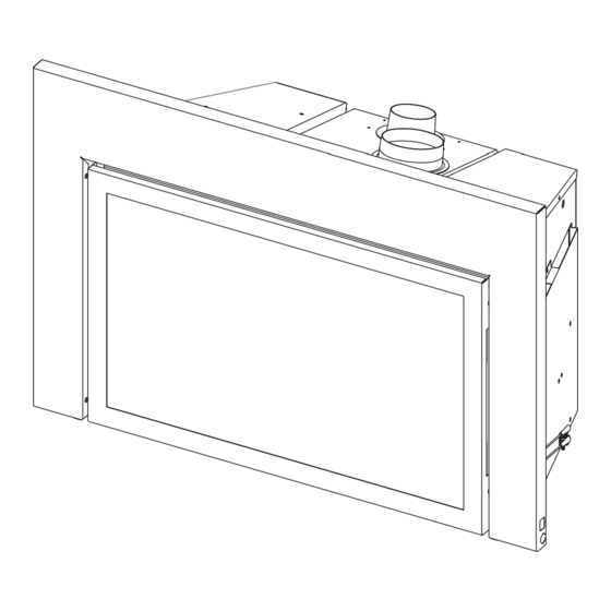
Page 11: Fireplace Insert Dimensions
FIREPLACE INSERT DIMENSIONS FLUE INTAKE 4" DIA 3" DIA 2.375” DVCT30 DVCT35 INDEX DIMENSION DESCRIPTION LETTER (Dimensions in inches) The maximum height of fireplace face The maximum width of fireplace face 30-11/16 34-3/4 The maximum depth of fireplace 17-9/16 18-9/16 The height of the fireplace opening (not shown) 15-3/4 20-3/4... -
Page 12: Minimum Fireplace Opening Dimensions
MINIMUM FIREPLACE OPENING DIMENSIONS (Dimensions in inches) 8” MIN. DIA. FLUE REQUIRED Model Height Front Depth Rear Width B Width D DVCT30 19-1/2 31-1/4 DVCT35 24-1/2 35-1/4 25-3/4 *Subtract surround depth from dimension C. MANTEL AND TRIM CLEARANCES Combustible Material CEILING 12”... -
Page 13: Gas Supply
GAS SUPPLY If the fireplace where you are installing the insert has no gas line Use the following gas connectors: access hole, drill an access hole of 1.5 inch (37.5 mm) or less — ANSI Z21.24 Appliance Connectors of Corrugated Metal through the lower sides or bottom of the firebox. -
Page 14: Electrical Considerations
GAS SUPPLY (CONT’D) Installing a New Main Gas Shut-Off Valve Checking Manifold Pressures Each appliance must have its own manual gas shut-off valve Both Propane and Natural Gas valves have a built-in pressure located in close proximity. Where none exists, or where its size regulator. -
Page 15: Fireplace Preparation
FIREPLACE PREPARATION Before You Start 8” DIAMETER FLUE (MIN.) Before installing, read these instructions and the Vent Kit Instructions to ensure proper installation. Consult local Building Codes before beginning the Installation. INTERIOR BAFFLES, NOTICE: Cutting the sheet metal parts of an existing fireplace to SMOKE SHIELDS, AND install the fireplace insert is prohibited unless mentioned below. -
Page 16: Venting
VENTING Vent System Installation Precautions NOTICE: The minimum vertical vent rise is 10 feet and the Before installing vent kits, read these instructions and the vent kit maximum vertical vent rise is 40 feet. These dimensions are Instructions. Consult local Building Codes before beginning the measured from the starting collars of the unit to the end of the Installation. -
Page 17: Vertical Termination
VERTICAL TERMINATION Determining Minimum Vent Height Above the Roof. Vertical Applications The Gas Fireplace Insert has been approved for vertical NOTICE: Major U.S. building codes specify minimum chimney installations up to 40 feet in height (starting of collars to end height above the roof top. -
Page 18: Installation
INSTALLATION CAUTION CAUTION The vent cap and vent tubing have sharp edges. Wear Seal off the area between the termination cap and the top gloves when unpacking and installing. of the solid-fuel chimney opening into which the vent cap is installed to avoid downdrafts and/or cold air problems. Connect the Vent Pipe and Install the Fireplace Insert For fireplace vent pipe and insert installation refer to information 1 through 6 below. - Page 19 INSTALLATION (CONT’D) 8. Set insert in front of fireplace opening. 14. Work the insert into the fireplace cavity as you pull forward on the vent slide plate. Do not use excessive force on the 9. If necessary, remove the 2 hex screws from the vent slide vent slide plate.
- Page 20 INSTALLATION (CONT’D) 20. Sync Remote. 18. Remove barrier screen assembly by lifting the screen assembly and pulling it toward you. See Figure 16. Push the sync button to the right of the insert. See Figure 18. With the batteries already installed in the transmitter, push the CAUTION ON button.
- Page 21 INSTALLATION (CONT’D) 21. Reinstall door assembly removed in step 19. 22. Adjust damper and air shutter for perfect burn. Allow about 15 minutes for flame to stabilize. See Figures 19-21 and the following two tables. R E W IN G S C R E T A IN S E D 1 /4 C L O...
- Page 22 INSTALLATION (CONT’D) REAR BURNER AIR SHUTTER GUIDELINES 24. Seasonal switch must be in "ON" position. DVCT30 VENT LENGTH Propane Natural 10 ft Open Full Closed 20 ft 1/2 - 3/4 Closed Full Closed 30 ft 1/2 - 3/4 Closed Full Closed 40 ft 1/2 Closed Full Closed...
-
Page 23: Ipi System Electronic System Wiring Diagram
IPI ELECTRONIC SYSTEM WIRING DIAGRAM BLUE PINK BLUE BLACK BLACK SOLENOID VALVE SYNC BUTTON If any of the original wire as supplied with this unit must be WARNING replaced, it must be replaced with equivalent gauge and ELECTRICAL GROUNDING INSTRUCTIONS temperature rated wire. -
Page 24: Intermittent Pilot Lighting Instructions
INTERMITTENT PILOT LIGHTING INSTRUCTIONS FOR YOUR SAFETY READ BEFORE LIGHTING WARNING If you do not follow these instructions exactly, a fire or explosion may result causing property damage, personal injury or loss of life. A. This appliance is equipped with an ignition device which C. -
Page 25: Safety Information For Users Of Propane
SAFETY INFORMATION FOR USERS OF PROPANE GAS Propane is a flammable gas which can cause fires and Propane Gas may stratify in a closed area, and the odor intensity explosions. In its natural state, propane is odorless and could vary at different levels. Since it is heavier than air, there colorless. -
Page 26: Multifunction Remote Operating Instructions
MULTIFUNCTION REMOTE OPERATING INSTRUCTIONS Figure 25 CPI Mode – In the “Pilot On Demand” mode, the pilot remains ON TECHNICAL DATA continuously even when the burner is turned OFF. The pilot will Remote Control shut off after 7 days if there is no activity or call for heat. 4.5 V (three 1.5 V Supply voltage AAA batteries) - Page 27 MULTIFUNCTION REMOTE OPERATING INSTRUCTIONS Initializing the System Temperature Indication Display °C or °F Install three AAA batteries into the battery bay located on the With the system in the “OFF” position, press the Thermostat base of the transmitter. See Figure 27. Button and the Mode Button at the same time.
- Page 28 MULTIFUNCTION REMOTE OPERATING INSTRUCTIONS Turn On the Appliance With the system OFF, press the ON/OFF Button on the Transmit- ter. The Transmitter display will show some other active Icons on the screen. At the same time the Receiver will activate the appli- ance.
- Page 29 MULTIFUNCTION REMOTE OPERATING INSTRUCTIONS Room Thermostat (Transmitter Operation) The Remote Control can operate as a room thermostat. The thermostat can be set to a desired temperature to control the comfort level in a room. To activate this function, press the Ther- mostat Button (Figure 26).
- Page 30 MULTIFUNCTION REMOTE OPERATING INSTRUCTIONS Remote Dimmer Control (Light) To activate the light, use the Mode Button (Figure 26) to index to the light icon. See Figures 42 and 43. The intensity of the output can be adjusted through six levels. Use the Up/Down Arrow Buttons (Figure 26) to adjust the output level.
- Page 31 MULTIFUNCTION REMOTE OPERATING INSTRUCTIONS Button Lock Battery Backup Operation This function will lock the Buttons to avoid unsupervised operation. Install batteries (See initialization sequence on page 4 or 11). To activate this function, press the MODE and UP Buttons at the In case of power loss, the fireplace will switch to battery mode same time.
-
Page 32: Intermittent Control System Troubleshooting
INTERMITTENT CONTROL SYSTEM TROUBLESHOOTING Brief Description of the Components The controls are designed to be used with either Propane or Natural Gas and can be converted by use of an OEM supplied conversion kit. The Intermittent Fireplace Control (IFC) is an automatic gas ignition system based on a single microcontroller core. - Page 33 INTERMITTENT CONTROL SYSTEM TROUBLESHOOTING PROBLEM OBSERVED POSSIBLE CAUSE CORRECTIVE MEASURE What To Do If You Smell Gas • Do not try to light any appliance. Gas odor during setup • Do not touch any electrical switch; • Do not use any phone in your building. Gas Leak •...
- Page 34 INTERMITTENT CONTROL SYSTEM TROUBLESHOOTING PROBLEM OBSERVED POSSIBLE CAUSE CORRECTIVE MEASURE Low gas pressure Check gas supply pressure Loose sensor wire Check wire connection Valve not grounded well Check ground connections Clogged or dirty burner ports Clean burner ports Burner lights but does not Move remote away from fireplace Room temperature is higher than stay lit while pilot remains on...
-
Page 35: Insert Parts List
INSERT PARTS LIST PART NUMBER INDEX DVCT30 DVCT35 DESCRIPTION NATURAL PROPANE NATURAL PROPANE DVCT30 Firebox R12428 R12428 R12428 R12428 Blower Assembly 37911 37911 38529 38529 Slider Gasket Assembly R12258 R12258 Catalyst R12488 R12488 R12258 R12258 Catalyst R12279 R12279 R12476 R12476 Catalyst R11837 R11837... -
Page 36: Insert Parts View
INSERT PARTS LIST (CONT’D) PART NUMBER INDEX DVCT30 DVCT35 DESCRIPTION NATURAL PROPANE NATURAL PROPANE R11550 R11550 R11550 R11550 Transmitter - Remote R11515 R11515 R11515 R11515 Cord Set R12462 R12462 R12462 R12462 Module - Switch/Blower Wire Harness (2 req’d) R11524 R11524 R11524 R11524 Receiver Wire Harness... -
Page 37: Maintenance And Service
MAINTENANCE AND SERVICE FOR THE INSTALLER Maintenance Precautions Installation and repair should be done by a qualified service person. The fireplace should be inspected before use and at least annually by a qualified service person. More frequent cleaning might be required due to excessive lint from carpeting, bedding material, etc. -
Page 38: Important Safety Information
IMPORTANT SAFETY INFORMATION Before enclosing the vent pipe assembly, operate the appliance to ensure it is venting properly. DO NOT OPERATE THIS APPLIANCE WITHOUT GLASS FRONT PANEL INSTALLED WARNING 6. “Clothing or other flammable material should not be 1. “Due to high temperatures, the appliance should be located out of traffic and away from furniture and placed on or near the appliance.”... -
Page 39: Master Parts Distributor List
This list changes from time to time. For the current list, please click on the Master Parts button at www.empirecomfort.com. Please note: Master Parts Distributors are independent businesses that stock the most commonly ordered Original Equipment repair parts for Heaters, Grills, and Fireplaces manufactured by Empire Comfort Systems Inc. Dey Distributing F. -
Page 40: Warranty
WARRANTY Empire Comfort Systems Inc. warranties this hearth product to be free from defects at the time of purchase and for the periods specified below. Hearth products must be installed by a qualified technician and must be maintained and operated safely, in accordance with the instructions in the owner’s manual. - Page 41 Empire Comfort Systems Inc. Belleville, IL If you have a general question about our products, please e-mail us at info@empirecomfort.com. If you have a service or repair question, please contact your dealer. www.empirecomfort.com Page 40 41961-0-0420...
Need help?
Do you have a question about the DVCTCBN95K-2 and is the answer not in the manual?
Questions and answers