Advertisement
Installation Instructions
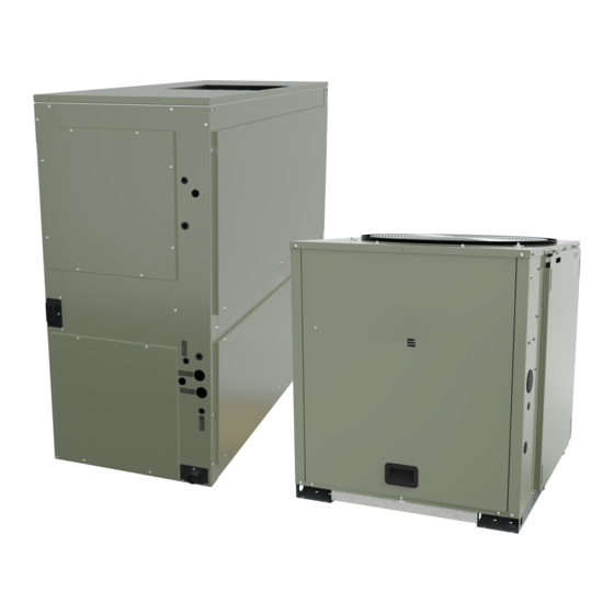
Split System Air Conditioners
Odyssey™
Single Zone VAV to 2-Speed Electromechanical
TWE Air Handlers R-410A and Symbio™
(Digit 15 = D)
Model Number: Used With:
BAYWRKT510*
TWE with R-410A and Symbio™ controls
Only qualified personnel should install and service the equipment. The installation, starting up, and servicing of heating, ventilating, and air-conditioning equipment
can be hazardous and requires specific knowledge and training. Improperly installed, adjusted or altered equipment by an unqualified person could result in death or
serious injury. When working on the equipment, observe all precautions in the literature and on the tags, stickers, and labels that are attached to the equipment.
September 2024
SAFETY WARNING
PART-SVN265A-EN
Advertisement
Table of Contents

Related Manuals for Trane Odyssey BAYWRKT510 Series


Summary of Contents for Trane Odyssey BAYWRKT510 Series
- Page 1 Installation Instructions Split System Air Conditioners Odyssey™ Single Zone VAV to 2-Speed Electromechanical TWE Air Handlers R-410A and Symbio™ (Digit 15 = D) Model Number: Used With: BAYWRKT510* TWE with R-410A and Symbio™ controls SAFETY WARNING Only qualified personnel should install and service the equipment. The installation, starting up, and servicing of heating, ventilating, and air-conditioning equipment can be hazardous and requires specific knowledge and training.
-
Page 2: Warnings, Cautions, And Notices
Chlorine, Fluorine and Carbon (CFCs) and those containing Hydrogen, Chlorine, Fluorine and Carbon (HCFCs). Not all refrigerants containing these compounds have the same potential impact to the environment. Trane advocates the responsible handling of all refrigerants. - Page 3 Non-Trane personnel should always follow local regulations. Copyright This document and the information in it are the property of Trane, and may not be used or reproduced in whole or in part without written permission. Trane reserves the right to revise this publication at any time, and to make changes to its content without obligation to notify any person of such revision or change.
-
Page 4: General Information
For variable frequency drives or other energy storing components provided by Trane or others, refer to the appropriate manufacturer’s literature for allowable waiting periods for discharge of capacitors. Verify with a CAT III or IV voltmeter rated per NFPA 70E that all capacitors have discharged. - Page 5 General Information Table 2. Label instructions Parameters Description VFD Label Locate the label with new VFD parameters and adhere it on top of the old label. Unit Conversion Locate the label (Part number: X39004549001) which states, “This unit has been converted to 2-speed airflow for pairing with Label electromechanical condenser (Model digit 15 = D has been converted to digit 15 = C)”...
-
Page 6: Installation
Installation SZVAV Symbio Air Handler to Two-Speed Air Handler with Electromechanical Condenser Pairing 1. Remove power from the air handler unit and condenser (condenser provides low voltage power to air handler unit). 2. Remove Modbus harness from relay board P1. 3. - Page 7 Installation 3. Connect VFD pigtail harness P11 to relay board J11. Figure 4. Harness routing and connection to relay board Relay Board 4. Connect VFD pigtail harness PPM53 to VFD harness PPF53. 5. Apply power to air handler unit and condenser. 6.
-
Page 8: Units With Electric Heat
Installation Units with Electric Heat 1. Remove the electric heat wiring between options module and relay board P1. 2. Remove IMC connection from options module P5 and relay board J2. 3. Remove remaining connectors from options module and remove options module. Air Handler Unit Placement Figure 5. - Page 9 Notes PART-SVN265A-EN...
- Page 10 Notes PART-SVN265A-EN...
- Page 11 Notes PART-SVN265A-EN...
- Page 12 For more information, please visit trane.com or americanstandardair.com. Trane and American Standard have a policy of continuous product and product data improvement and reserve the right to change design and specifications without notice. We are committed to using environmentally conscious print practices.
Need help?
Do you have a question about the Odyssey BAYWRKT510 Series and is the answer not in the manual?
Questions and answers