Table of Contents
Advertisement
Quick Links
Advertisement
Table of Contents

Related Manuals for TRENDnet TV-IP121W


Summary of Contents for TRENDnet TV-IP121W
-
Page 2: Preface
Preface Thank you for purchasing the TV-IP121W, a powerful and high- quality image SecurView Wireless Day/Night Internet Camera. The infrared LEDs and light sensor enable the camera to capture images even in dark environments. The camera can be installed as a... -
Page 3: Table Of Contents
Contents PREFACE ................1 CHAPTER 1 ..............4 INTRODUCTION TO YOUR CAMERA ....4 1.1 C ........4 HECKING THE ACKAGE ONTENTS 1.2 G ........5 ETTING TO AMERA 1.3 F ............. 8 EATURES AND ENEFITS 1.4 S ............9 YSTEM EQUIREMENT CHAPTER 2 .............. - Page 4 4.10 I ..............53 NFORMATION CHAPTER 5 ..............55 APPENDIX ..............82 A.1 S ..............82 PECIFICATION A.2 G ............84 LOSSARY OF ERMS LIMITED WARRANTY ..........93 - 3 -...
-
Page 5: Chapter 1
HAPTER NTRODUCTION AMERA 1.1 Checking the Package Contents Check the items contained in the package carefully. You should have the following: TV-IP121W AC Power Adapter (5VDC, 2.5A) Detachable External Antenna Camera Stand Ethernet Cable (RJ-45 type) ... -
Page 6: Getting To Know Your Camera
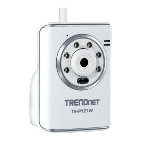
1.2 Getting to Know Your Camera Internal Microphone Power LED indicates allows the camera to the camera is powered receive sound and voice on with the steady amber light. Infrared LEDs (optional) Link LED indicates allows your camera to the camera’s network capture clear images in a connectivity with the dark environment... -
Page 7: Rear View
External Antenna Screw Hole is used to connect the camera stand. Ethernet Cable Connector is used to connect the DC Power Connector network cable, which supports is used to connect the the NWay protocol so that the AC power adapter, in camera can detect the order to supply power network speed automatically. - Page 8 Internal Microphone: It allows the camera to receive the sound or voice Infrared LEDs: It allows your camera to capture clear images in a dark environment. Light Sensor: It is used to trigger on and off the Infrared LEDs according to the environmental light level. Power LED: A steady orange light indicates the camera is powered on.
-
Page 9: Features And Benefits
1.3 Features and Benefits Audio Capability The built-in microphone of the camera provides on-the-spot audio via the Internet, allowing you to monitor the on-site voice. Day & Night Surveillance Supported The six Infrared LEDs around the standard lens assembly (optional) enable the camera to capture crystal clear images in the dark environment or at night. -
Page 10: System Requirement
1.4 System Requirement Networking LAN: 10Base-T Ethernet or 100Base-TX Fast Ethernet. WLAN: IEEE 802.11b/g. Accessing the Camera using Web Browser Platform: Microsoft® Windows® 2000/XP/Vista/Windows 7 CPU: Intel Pentium III 350MHz or above RAM: 128MB Resolution: 800x600 or above User Interface: Microsoft®... -
Page 11: Chapter 2
HAPTER ARDWARE NSTALLATION 2.1 Installing the Camera Stand The camera comes with a camera stand, which uses a swivel ball screw head to lock to the camera’s screw hole. When the camera stand is attached, you can place the camera anywhere by mounting the camera through the three screw holes located in the base of the camera stand. -
Page 12: Connecting The Camera To Lan/Wlan
2.2 Connecting the Camera to LAN/WLAN Use the provided Ethernet cable to connect the camera to your local area network (LAN). When you connect the AC power adapter, the camera is powered on automatically. You can verify the power status from the Power LED on the front panel of the camera. -
Page 13: Applications Of The Camera
2.3 Applications of the Camera The camera can be applied in multiple applications, including: Monitor local and remote places and objects via Internet or Intranet. Capture still images and video clips remotely. Upload images or send email messages with the still images attached. -
Page 14: Chapter 3
HAPTER CCESSING THE AMERA 3.1 Using IPSetup The camera comes with a convenient utility, IPSetup, which is included in the Installation CD-ROM, allowing you to search the camera on your network easily. 1. Insert the Installation CD-ROM into your computer’s CD-ROM drive to initiate the Auto-Run program. - Page 15 3. Click Browse to choose the desired destination location. By default, the destination location is C:\Program Files\TRENDnet\IPSetup. Then click Next. - 14 -...
- Page 16 4. Click Next to confirm the IPSetup software to be installed to the computer. 5. When the Installation Complete window appears, click Close. - 15 -...
- Page 17 6. After installing the IPSetup utility, the application is automatically installed to your computer, and creates a folder in Start\Program\TRENDnet\IPSetup. 7. Click Start>Programs>TRENDnet>IPSetup, and then click IPSetup. 8. The IPSetup window will appear. It will search for the camera within the same network...
- Page 18 Camera Display Area: It shows the connected camera(s) within the same network Double click the IP Address, it will link to the Camera’s Web Configuration page. Change IP: Click this button to bring up the following window. It allows you to change the IP Address. You can select either Static IP or click DHCP.
-
Page 19: Accessing To The Camera
3.2 Accessing to the Camera Whenever you want to access the camera: 1. Open the Web browser on your computer (example showed in the User’s Guide is based on the Internet Explorer). 2. Type the default IP address (192.168.10.30) or the IP address found by IPSetup in the Address bar, and then press [Enter]. - Page 20 depends on the Internet security settings of your computer. Click Yes to proceed. After you login into the Web Configuration of the camera, the main page will appear as below: Zoom In Buttons Camera Information Live View/Setup Nightmode Button Function Buttons Live View Image The main page of the Web Configuration provides you with many useful information and functions, including:...
- Page 21 – Live View Image Displays the real-time image of the connected camera. – Live View/Setup Switch Click Setup to configure the camera. For details, see Chapter 4. – Function Buttons Use these buttons to control the video functions.
-
Page 22: Configuring The Ip Address Of The Pc
3.3 Configuring the IP Address of the PC If you failed to access the camera, please check the IP address of your computer. When you connect the camera to your computer directly to proceed with configuration of the camera, you need to set up the IP Addresses to be in the same segment for the two devices to communicate. -
Page 23: Chapter 4
HAPTER ONFIGURING THE AMERA 4.1 Using the Web Configuration You can access and manage the camera through the Web browser and the provided software application SecurView™ (see chapter 5 in more detail). This chapter describes the Web Configuration, and guides you through the configuration of the camera by using the web browser. -
Page 24: Using Smart Wizard
The Web Configuration contains the settings that are required for the camera in the left menu bar, including Smart Wizard, Basic, Network, Video, Event Server, Motion detect, Event Config, Tools, and Information. 4.2 Using Smart Wizard The camera’s Smart Wizard lets you configure your camera easily and quickly. - Page 25 Enter Camera name, Location, New Admin password and enter again to confirm Admin password Step 2. IP Settings Select the IP setting according to your network: DHCP, Static IP, or PPPoE. Step 3. Email Settings - 24 -...
- Page 26 Enter the required information to be able to send email with an image Step 4. Wireless Networking Select Enable to enable the wireless function of the camera, and then complete the required settings. - 25 -...
- Page 27 Step 5. Confirm Settings This step shows all the setting information you imputed. This step shows the configuration of your camera. When you confirm the settings, click Apply to finish the wizard and reboot the camera. Otherwise, click Prev to go back to the previous step(s) and change the settings;...
-
Page 28: Basic Setup
4.3 Basic Setup The Basic menu contains three sub-menus that provide the system settings for the camera, such as the Camera Name, Location, Date & Time, and User management. - 27 -... - Page 29 Basic >> System Basic - Camera Name: Enter a descriptive name for the camera. - Location: Enter a descriptive name for the location used by the camera. Indication LED This item allows you to set the LED illumination as desired. There are two options: Normal and OFF.
- Page 30 Basic >> Date & Time Date & Time - TimeZone: Select the proper time zone for the region from the pull-down menu. - Synchronize with PC: Select this option and the date & time settings of the camera will be synchronized with the connected computer.
- Page 31 Basic >> User Administrator To prevent unauthorized access to the camera’s Web Configuration, you are strongly recommend to change the default administrator password. Type the administrator password twice to set and confirm the password. General User - User Name: Enter the user’s name you want to add to use the camera.
- Page 32 - User List: Display the existing users of the camera. To delete a user, select the one you want to delete and click Delete. Guest - User Name: Enter the guest’s name you want to add to use the camera. - Password: Enter the password for the new guest.
-
Page 33: Network Settings
4.4 Network Settings The Network menu contains three sub-menus that provide the network settings for the camera, such as the IP Setting, DDNS Setting, IP Filter, and Wireless network. - 32 -... - Page 34 Network >> Network IP Setting This item allows you to select the IP Address mode and set up the related configuration. - DHCP: Select this option when your network uses the DHCP server. When the camera starts up, it will be assigned an IP address from the DHCP server automatically.
- Page 35 - Static IP: Select this option to assign the IP address for the camera directly. You can use IP Setup to obtain the related setting values. Enter the IP address of the camera. The default setting is 192.168.10.30. Subnet Mask Enter the Subnet Mask of the camera.
- Page 36 UPnP The camera supports UPnP (Universal Plug and Play), which is a set of computer network protocols that enable the device-to- device interoperability. In addition, it supports port auto mapping function so that you can access the camera if it is behind an NAT router or firewall.
- Page 37 For example, when you enter 192.168.10.50 in Start IP Address and 192.168.10.80 in End IP Address, the user whose IP address located within 192.168.10.50 ~ 192.168.10.80 will not be allowed to access the camera. Deny IP List The list displays the range setting(s) of IP addresses that are not allowed to access the camera.
- Page 38 - Network ID (SSID}: Keep the default setting of this option to connect the camera to any access point under the infrastructure network mode. To connect the camera to a specified access point, set a SSID for the camera to correspond with the access point’s ESS-ID.
- Page 39 WPA-PSK/ WPA-PSK/WPA2-PSK is specially designed for WPA2-PSK the users who do not have access to network authentication servers. The user has to manually enter the starting password in their access point or gateway, as well as in each PC on the wireless network.
-
Page 40: Setting Up Video & Audio
4.5 Setting up Video & Audio The Video & Audio menu contains three sub-menus that provide the video and audio settings for the camera. Video & Audio >> Camera - 39 -... - Page 41 Image Setting - Brightness: Adjust the brightness level from 0 ~ 100. - Contrast: Adjust the contrast level from 0 ~ 100. - Saturation: Adjust the colors level from 0 ~ 100 Click Default to restore the default settings of the three options above.
- Page 42 Video & Audio >> Video MJPEG - Video Resolution: Select the desired video resolution from the three formats: VGA, QVGA and QQVGA. The higher setting (VGA) obtains better video quality while it uses more resource within your network. - Video Quality: Select the desired image quality from five levels: Lowest, Low, Medium, High, and Highest.
-
Page 43: Event Server Configuration
4.6 Event Server Configuration The Event Server menu contains two sub-menus that allow you to upload images to FTP, and send emails that include still images. When you complete the required settings for FTP, or Email, click Test to test the related configuration is correct or not. Once the camera connects to the server successfully, click Apply. - Page 44 Event Server Setting>> FTP - Host Address: Enter the IP address of the target FTP server. - Port Number: Enter the port number used for the FTP server. - User Name: Enter the user name to login into the FTP server. - Password: Enter the password to login into the FTP server.
- Page 45 Event Server Setting >> Email Email - SMTP Server Address: Enter the mail server address. For example, mymail.com. - Sender Email Address: Enter the email address of the user who will send the email. For example, John@mymail.com. - Authentication Mode: Select None to disable the authentication feature, or select SMTP and then enter the User Name and Password according to the mail server configuration.
-
Page 46: Motion Detect
- Receiver #2 Email Address: Enter the second email address of the user who will receive the email. 4.7 Motion Detect The Motion Detect menu contains the command and option that allow you to enable and set up the motion detection feature of the camera. -
Page 47: Event Config
- Threshold: Move the slide bar to adjust the level for detecting motion to record video. 4.8 Event Config The Event Config menu contains four sub-menus that provide the commands to configure event profiles. - 46 -... - Page 48 Event Configuration >> General Setting - Snapshot/Recording Subfolder: You can assign a given sub- folder for captured file. Otherwise, leave this option blank to use the default setting. Event Configuration >> Arrange Schedule Profile This sub-menu displays the scheduled profile(s). To customize the profile, click Add and then enter a descriptive name for the profile in the prompt dialog window.
- Page 49 After entering the profile name, click OK and the profile is added to the Schedule Profiles list. To delete the profile, select the profile in the list and click Delete. - Profile Name: Display the profile name that you select in the Schedule Profiles list.
- Page 50 - Weekdays: Select the weekday(s) that you want to separately assign in the schedule profile. The weekday that has been assigned will be displayed with green color. - Time List: Display the time period that you have assigned within the selected weekday. To assign the same time period to every weekday, click Add this to all weekdays;...
- Page 51 - Action: Select the destination that the captured images will be sent to: Send Email, or FTP Upload. Event Configuration >> Schedule Trigger You can separately configure the schedule for trigger function of the camera by Email, or FTP. Select the Enable option on each item, and then select a Schedule Profile from the pull-down list and set the Interval time.
-
Page 52: Tools
4.9 Tools The Tools menu provides the commands that allow you to restart or reset the camera. You can also backup and restore your configuration, and upgrade the firmware for the camera. - 51 -... - Page 53 Factory Reset Click Reset to restore all factory default settings for the camera. System Reboot Click Reboot to restart the camera just like turning the device off and on. The camera configuration will be retained after rebooting. Configuration You can save your camera configuration as a backup file on your computer.
-
Page 54: I Nformation
4.10 Information The Information menu displays the current configuration and events log of the camera. Device Info Display the Basic, Video, Network, and Wireless settings of the camera. - 53 -... - Page 55 System Log The Logs table displays the events log recorded by the system. - 54 -...
- Page 56 HAPTER SECURVIEW™ SOFTWARE This chapter describes detailed instructions on operating SecurView™ software, a useful friendly application for ease of control and navigation requirement. Installation Insert the Installation CD-ROM into your computer’s CD- ROM drive to initiate the Auto-Run program. Click the SecurView From the Auto-Run menu screen - 55 -...
- Page 57 NOTE To use SecurView™, you must have Microsoft .NET Framework 2.0 installed in the computer. The setup wizard will detect it and, if the program is not installed yet, ask you to install it during the process of installing SecurView™. Then SecurView Setup Wizard will appear.
- Page 58 Click Browse to choose the desired destination location. By default, the destination location is C:\Program Files\TRENDnet\SecurView. Then click Next. - 57 -...
- Page 59 Click Next to confirm the SecurView software to be installed to the computer - 58 -...
- Page 60 When the Installation Complete window appears, click Close. After installing the IPSetup utility, the application is automatically installed to your computer, and creates a folder in Start\Program\TRENDnet\SecurView. - 59 -...
-
Page 61: Using Installation
Using Installation To launch the program, click Start>Program>TRENDnet>SecurView, and then click SecurView™. The main screen will appear as below. NOTE Please set the resolution to 1024 x 768 or above on your computer while using SecurView™; otherwise, the displayed main screen may be distorted. - Page 62 SETTING: Click to enter the Setting screen of SecurView™. Click again to return to the main screen of SecurView™. Play: Click to play the recorded video file using the media player on the computer (for example, Windows Media Player by default). Lock: Click to lock the camera controls.
- Page 63 ALL RECORD: Click to start recording video clips using ALL connected cameras. To stop recording, please click Record button to stop the individual camera. Please note: stop recording only stops the manual recording camera. For Schedule recording, please change the setting on configuration.
- Page 64 NEXT: When multiple cameras connected, click this button to switch the video view to the next camera. To set the time interval of scanning, click SETTING > Other and then adjust the time from 1 to 10 seconds in the Time interval of scan option.
- Page 65 LISTEN: Click to receive the on-site sound and voice from the camera. SYSTEM Panel This panel displays the current date and time. Video View Window and Camera List Video Viewing Window Camera List - 64 -...
- Page 66 Video Viewing Window: This window displays the video view of the selected camera, which can be divided into 4/9/16 windows according to your selection in VIEW SELECTION panel. Camera List: This list displays the information of the connected camera(s). To add a camera 1.
- Page 67 3. In the pop-up Add New Camera dialog window, you can: Select the Search tab if you are not sure of the camera’s IP Address. Click Search camera to search for an available camera within the network. Once the camera is found and is shown in the list, select it and click Add Camera.
- Page 68 4. Enter the User name and Password for the camera, and then click OK. The connected camera will be displayed in the Camera’s List. 5. Click SETTING to return to the Video View Window. The video view of the selected camera will be displayed now. - 67 -...
-
Page 69: To Remove A Camera
To remove a camera 1. Click SETTING in the CONTROLS panel to display the Setting screen. 2. Select a camera from the list and click Delete Camera. - 68 -... -
Page 70: To Link To The Web Page Of The Camera
Select a camera Delete a camera To link to the Web page of the camera Click SETTING>Camera List>Camera Configuration and then Link web page to launch the Web browser that displays live view image and Web Configuration of the selected camera. - 69 -... -
Page 71: To Record Video
To Record Video SecurView™ provides three methods to record video clips: one is to click the RECORD/All Record button to record manually; the second is to record by motion detection; the third is to set the recording schedule in Setting>Recording Configuration>Schedule Recording Configuration. - Page 72 Trigger recording by motion detection When the motion detection function of the selected camera is enabled, you can configure the camera to start recording triggered by the motion detected. Click SETTING>Motion Configuration, and then select the Recording option to enable the selected camera to record by motion detection.
- Page 73 Schedule Recording Configuration This recording method will work after you have completed the required settings in the Schedule Recording Configuration. The recording schedule can be defined by Dates or Days. Dates: Select the camera from the pull-down list. - 72 -...
- Page 74 Select a camera Add Schedule Then, click Add to set the Start/Stop date and time and then click OK to add the recording schedule to the list. Click Apply to save the settings. - 73 -...
- Page 75 Days: First, select the camera from the pull-down list and select Days tab. Then, select the weekday from the day buttons and then set the time period. Click Apply to save the settings. - 74 -...
-
Page 76: To Configure The Recording Settings
To configure the recording settings To configure the recording settings, including the storage folder and storage options, click SETTING>Recording Configuration. - 75 -... - Page 77 Recording File Path: To change the destination folder to save the recorded video file, click Browse under the Recording File Path box to assign a new folder. Each Recording File Size: This option allows you to select from 20 to 100 MB so that the video will be recorded as another file automatically when the recording file reaches the specified size limit.
-
Page 78: To Playback The Recorded Video
Enable Recycle Recording: Click on the camera number to clear the files when the unreserved space of the hard disk drive is full. To playback the recorded video The recorded video clips are saved in your computer, and can be played using the media player on the computer, such as Windows Media Player. -
Page 79: To Set Up Motion Detection Options
code from http://www.xvid.org/downloads.15.0.html support. To set up motion detection options When the motion detection function of the selected camera is enabled, you can set the Motion Options by selecting Alarm, Recording, Send e-Mail, and Trigger Out under SETTING> Motion Configuration. ... - Page 80 Recording: Select this option to enable the camera to record by motion detected. Send Email: Select this option so that the system will be able to send an email to the specified receiver. Once the option is selected, you have to complete the required information in SETTING>Motion Configuration>Email Configuration.
- Page 81 User Name: Enter the user name to login the mail server. Password: Enter the password to login the mail server. Subject: Enter a subject for the notification email. Trigger Out: If the selected camera supports Trigger Out connector, select this option to enable the Trigger out function.
- Page 82 Information Click SETTING>About to display the information of the software application. - 81 -...
-
Page 83: Appendix
HAPTER PPENDIX A.1 Specification Image Sensor Sensor 1/4” color CMOS Resolution 640x480 Video Compression MJPEG Video resolution VGA/QVGA/QQVGA; 30fps max. System Hardware Processor ARM9 base 16MB SDRAM 4MB NOR Flash Power DC 5V Communication 10/100Mbps Fast Ethernet, auto-sensed, Auto-MDIX WLAN IEEE 802.11b/g... - Page 84 LEDs Power LED (amber); Link LED (green) Audio Input Built-in MIC Codec Software OS Support Windows 2000/XP/Vista Browser Internet Explorer 6.0 or above Apple Safari 2 or above Mozilla Firefox 2.00 or above Software Ultra View for playback/recording/ configuration features ...
-
Page 85: A.2 Glossary Of Term
A.2 Glossary of Terms NUMBERS 10BASE-T 10BASE-T is Ethernet over UTP Category III, IV, or V unshielded twisted-pair media. 100BASE-TX The two-pair twisted-media implementation of 100BASE- T is called 100BASE-TX. ADPCM Adaptive Differential Pulse Code Modulation, a new technology improved from PCM, which encodes analog sounds to digital form. - Page 86 workstation to give its own IP address. Communication Communication has four components: sender, receiver, message, and medium. In networks, devices and application tasks and processes communicate messages to each other over media. They represent the sender and receivers. The data they send is the message. The cabling or transmission method they use is the medium.
- Page 87 Enterprise An enterprise network consists of collections of networks network connected to each other over a geographically dispersed area. The enterprise network serves the needs of a widely distributed company and operates the company’s mission-critical applications. Ethernet The most popular LAN communication technology. There are a variety of types of Ethernet, including 10Mbps (traditional Ethernet), 100Mbps (Fast Ethernet), and 1,000Mbps (Gigabit Ethernet).
- Page 88 department. Short for hexadecimal refers to the base-16 number system, which consists of 16 unique symbols: the numbers 0 to 9 and the letters A to F. For example, the decimal number 15 is represented as F in the hexadecimal numbering system. The hexadecimal system is useful because it can represent every byte (8 bits) as two consecutive hexadecimal digits.
- Page 89 that “owns” that IP address. ISP (Internet Service Provider) is a company that maintains a network that is linked to the Internet by way of a dedicated communication line. An ISP offers the use of its dedicated communication lines to companies or individuals who can’t afford the high monthly cost for a direct connection.
- Page 90 Network Address Translator generally applied by a router that makes many different IP addresses on an internal network appear to the Internet as a single address. For routing messages properly within your network, each device requires a unique IP address. But the addresses may not be valid outside your network.
- Page 91 the Internet through a common broadband medium, such as DSL or cable modem. All the users over the Ethernet share a common connection. Protocol Communication on the network is governed by sets of rules called protocols. Protocols provide the guidelines devices use to communicate with each other, and thus they have different functions.
- Page 92 access to the content stream. Server It is a simple computer that provides resources, such as files or other information. SIP (Session Initiated Protocol) is a standard protocol that delivers the real-time communication for Voice over IP (VoIP), which establishes sessions for features such as audio and video conferencing.
- Page 93 ports. The User Datagram Protocol is a connectionless protocol that resides above IP in the TCP/IP suite User Name The USERNAME is the unique name assigned to each person who has access to the LAN. Utility It is a program that performs a specific task. Unshielded twisted-pair.
-
Page 94: Limited Warranty
The repair/replacement unit’s warranty continues from the original date of purchase. All products that are replaced become the property of TRENDnet. Replacement products may be new or reconditioned. TRENDnet does not issue refunds or credit. Please contact the point-of-purchase for their return policies. - Page 95 (RMA) number will be issued. An RMA number is required in order to initiate warranty service support for all TRENDnet products. Products that are sent to TRENDnet for RMA service must have the RMA number marked on the outside of return packages and sent to TRENDnet prepaid, insured and packaged appropriately for safe shipment.
- Page 96 ANY OTHER PERSON TO ASSUME FOR IT ANY OTHER LIABILITY IN CONNECTION WITH THE SALE, INSTALLATION MAINTENANCE OR USE OF TRENDNET’S PRODUCTS. TRENDNET SHALL NOT BE LIABLE UNDER THIS WARRANTY IF ITS TESTING AND EXAMINATION DISCLOSE THAT THE ALLEGED DEFECT IN THE PRODUCT DOES NOT EXIST OR WAS CAUSED BY CUSTOMER’S OR ANY THIRD PERSON’S MISUSE, NEGLECT,...
- Page 97 Download section and look for the desired TRENDnet product to access to the GPL Code or LGPL Code. These codes are distributed WITHOUT WARRANTY and are subject to the copyrights of the developers. TRENDnet does not provide technical support for these codes. Please go http://www.gnu.org/licenses/gpl.txt...
- Page 98 - 97 -...
Need help?
Do you have a question about the TV-IP121W and is the answer not in the manual?
Questions and answers