Table of Contents
Advertisement
Quick Links
Date: 5/23/2023
Return Request: 6/2/2023
Project: Farm Credit Office
Supplier: Falk
Submittal: Plumbing Equipment
Submittal Number: 22 30 00-01
Drawing # and Installation: Plumbing Drawings
ARCHITECT
Hight Jackson
5201 W. Village Parkway, Suite 300
Rogers, AR 72758
479-464-4965
GENERAL CONTRACTOR
Nabholz
612 Garland St.
Conway, AR 72032
501-505-5800
Notes:
ENGINEER
HAS Engineering
7405 Ellis Rd.
Fort Smith, AR 72916
479-452-8922
MECHANICAL SUBCONTRACTOR
Comfort Systems USA (Arkansas), Inc.
9924 Landers Rd.
N. Little Rock, AR 72117
501-834-3320
CSUSA PROJECT NO.
23-1013
jon@comfortar.com
Comfort Systems USA (Arkansas), Inc.
P.O. Box 16620
Little Rock, AR 72231
Phone 501-834-3320
Fax 501-834-5416
Advertisement
Table of Contents

Subscribe to Our Youtube Channel
Related Manuals for Watts 140H


Summary of Contents for Watts 140H
- Page 1 Comfort Systems USA (Arkansas), Inc. P.O. Box 16620 Little Rock, AR 72231 Phone 501-834-3320 Fax 501-834-5416 Date: 5/23/2023 Return Request: 6/2/2023 Project: Farm Credit Office Supplier: Falk Submittal: Plumbing Equipment Submittal Number: 22 30 00-01 Drawing # and Installation: Plumbing Drawings ARCHITECT ENGINEER Hight Jackson...
-
Page 2: Water Heater
WATER HEATER... - Page 3 Installation Manual and Owner’s Guide ANSI Z21.10.3 ・ CSA 4.3 540H only Models If the information in these instructions is not followed 140H exactly, a fire or explosion may 240H result causing property damage, WARNING personal injury or death. 340H...
- Page 4 Contents CONTENTS Installation Manual Owner's Guide SPECIFICATIONS ..........4 OPERATING SAFETY ........47 INTRODUCTION ..........5 NORMAL OPERATION ........49 SAFETY GUIDELINES........6 BUILT-IN CONTROLLER SAFETY DEFINITION ........6 AND REMOTE CONTROLLER ....49 GENERAL ............6 GENERAL ............49 INSTALLATION ..........7 OUTLET WATER TEMPERATURE GENERAL ............7 SETTING .............50 CLEARANCES ..........9 TEMPERATURE TABLE OF CONTROLLER .50 INCLUDED ACCESSORIES ......9...
- Page 5 Owner's Guide Owner's Guide Owner's Guide CONGRATULATIONS Congratulations and thank you for choosing our tankless water heater. Before use, we recommend that you read through this owner's guide carefully. Keep this manual for future reference. If you need an additional manual, contact the manufacturer or your local distributor.
-
Page 6: For Your Safety Read Before Operating
Owner's Guide Operating Safety OPERATING SAFETY FOR YOUR SAFETY READ BEFORE OPERATING WARNING: If you do not follow these instructions exactly, a fire or explosion may result causing property damage, personal injury or loss of life. A. This appliance does not have a pilot. It is equipped with an ignition device which automatically lights the burner. - Page 7 Owner's Guide Operating Safety DANGER Vapors from flammable liquids will explode and catch fire causing death or severe burns. Do not use or store flammable products such as gasoline, solvents or adhesives in the same room or area near the water heater. Do not install water heater where flammable products will be stored or used unless the main burner is at least 18”...
-
Page 8: Normal Operation
Normal Operation NORMAL OPERATION BUILT-IN CONTROLLER AND REMOTE CONTROLLER The illustration below shows an example of the controllers. The exact display may differ from examples. 140H built-in controller display is same orientation as remote controller image as shown below. Built-in controller... -
Page 9: Outlet Water Temperature Setting
The remote will emit a beep and change to 145 °F (63 °C). 4. Press the "HOT" button to set up to 160 °F (70 °C). TEMPERATURE TABLE OF CONTROLLER a) For 140H, 240H and 340H models °F 100 105 110 115 120* 125 130 135 140 °C... -
Page 10: Additional Features
Owner's Guide Normal Operation ADDITIONAL FEATURES -Information mode- You can get some information about the water heater condition by pressing the "INFO" button. For more information, follow the procedures below: Screen on the controller INFO Operation Button Built-in controller Remote controller Inlet water temperature will be Inlet water temperature 1st. -
Page 11: Temperature Settings On The Pcb
FLOW Household Flow Rates • The flow rate through the water heater is limited to a maximum of 7.0 GPM (26.5 L/min) for the 140H model, a Flow rate Appliance/Use maximum of 6.6 GPM (25 L/min) for the 240H model, 8.0... -
Page 12: Freeze Protection System
Owner's Guide Normal Operation FREEZE PROTECTION SYSTEM • This water heater comes equipped with heating blocks to protect it from damage associated with freezing. When the freeze protection thermostat senses air temperature below 36.5 °F (2.5 °C), the blocks will heat up to prevent freezing of the unit. -
Page 13: Maintenance And Service
Owner's Guide Maintenance and service MAINTENANCE AND SERVICE • Turn off the electrical power supply and close the manual gas shutoff valve and the manual water control valve before servicing. • Failure to do so could result in severe personal injury, or death. WARNING The following maintenance is required for the proper operation of water heaters. - Page 14 Unscrew this drain plug to drain the water line as well. 8. Securely screw the drain plugs back into place. Hand- tighten only. 140H 240H/340H/540H Drain plug Drain plug...
-
Page 15: Measuring Inlet Gas Pressure
Measure gas supply pressure at minimum heater operation: Reduce water flow so the heater is running at minimal operation. Press the MIN button on the computer board. (Refer to the diagrams below.) Take a supply gas pressure reading and verify that it is within the specified inlet gas pressure range. 140H/240H/340H 540H MIN button... -
Page 16: Troubleshooting
Owner's Guide Troubleshooting TROUBLESHOOTING PROBLEM SOLUTIONS It takes a long time to • The time it takes to deliver hot water from the water heater to your fixtures get hot water at the depends on the length of piping between the two. The longer the distance or fixtures. -
Page 17: Error Codes
The green LED on the computer board will flash in a pattern shown on the next page. • Consult the table on the following pages for the description of each error code. 140H/240H/340H 540H Error code indicator on the built -in... - Page 18 Owner's Guide Troubleshooting -Single unit Installation- Example: If your unit has a “321” error code (which signifies an inlet thermistor failure) • Indicator on the built-in controller or remote controller : “321” will be displayed on the screen. Error code •...
- Page 19 421, 423). • Ensure that any horizontal drain line runs are sloped downward. Removal any sags in the drain line. 311* 140H/240H/340H: Outlet Thermistor Failure Flashes 540H: Heat Exchanger • Check for connection/breakage of wires and/or debris on thermistor (Part Thermistor Failure #407, 408, 411, 715).
- Page 20 Owner's Guide Troubleshooting Controller Green Malfunction Diagnosis description 331* Outlet thermistor fail- ure (540H only) Flashes • Check for connection/breakage of wires and/or debris on thermistor (Part 341* Exhaust thermistor failure #407, 408, 411, 715, 718 721). (Indoor models only) Flashes 391* Air-fuel ratio rod fail-...
-
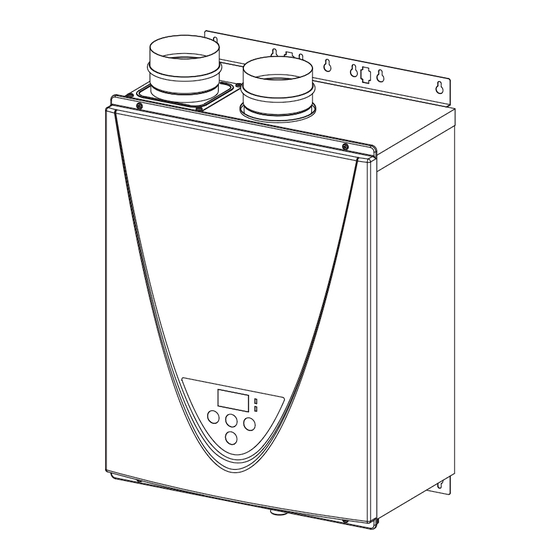
Page 21: Components Diagram
Owner's Guide Components Diagram COMPONENTS DIAGRAM Case assembly 140H Indoor 140H Outdoor Temperature Built-in controller remote controller 140H Indoor 140H 100209924 Page... -
Page 22: Computer Board Assembly
Owner's Guide Components Diagram Computer board assembly Surge box assembly 140H 140H Indoor model Outdoor model Wiring diagram Indoor only Heater (for the secondary heat exchanger) Heaters (for the heat exchanger and water pipes) 140H (for the drain hose) (for the water pipes) -
Page 23: Burner Assembly
Owner's Guide Components Diagram Burner assembly 140H Burner assembly 111 711 Manifold assembly 055 063 Page... -
Page 24: Water Way Assembly
Owner's Guide Components Diagram Water Way assembly 140H Indoor 140H Outdoor 425 471 472 065 450 053 for Indoor model 451 414 052 454 Water outlet section Water inlet section Page... -
Page 25: Case Assembly
Owner's Guide Components Diagram Case assembly 240H/340H/540H Indoor 240H/340H/540H Outdoor Built-in controller 240H/340H/540H Indoor Surge box assembly 240H/340H/540H Temperature remote controller 240H/340H/540H Page... - Page 26 Owner's Guide Components Diagram Computer board assembly 240H/340H 540H 707 722 Wiring diagram Heater 240H/340H Outdoor Only Igniter rod Heater 240H/340H Heater Heater Thermostat 240H/340H Indoor Only O.H.C.F Heater Ground Surge Heater Hi-limit Y BL O switch Heater 240H/340H Outdoor Only Drain plug detector AFR rod...
- Page 27 Owner's Guide Components Diagram Burner assembly 240H/340H/540H Burner assembly 109 111 Manifold assembly 540H Page...
- Page 28 Owner's Guide Components Diagram Water Way assembly 240H/340H/540H 540H 240H/340H Bypass section 540H Water outlet section Water inlet section Page...
-
Page 29: Parts List
Owner's Guide Parts list PARTS LIST Model Item # Description 140H 240H 340H 540H Case assembly Indoor Case assembly Outdoor Front cover Indoor 100074663 100074665 Front cover Outdoor 100074664 100074666 Intake air port assembly 100076311 100074667 Bracket Junction box 100074668... - Page 30 100337321 100074672 Fan motor for Indoor model 100074606 Fan motor for Outdoor model 100074228 Burner gasket 100074216 Fan damper for Indoor model (140H: Outdoor) 100074466 Fan damper for Indoor model (140H) 100076511 Burner window 100074218 Rod holder gasket 100074219 Flame rod...
- Page 31 Secondary heat exchanger for Outdoor model 100076508 100074701 3ʺ PVC adapter 100310706 Upper drain tube Band A Lower drain tube Secondary heat exchanger heater (140H) 100076328 Heater fixing plate (140H) Drain detector fixing plate Pipe heater fixing plate 100074273 Heater fixing plate 16 100074310...
- Page 32 120 VAC wire for Outdoor model 100074697 120 VAC Power ON-OFF switch 100074326 Remote controller wire (240H/340H/540H) 100074649 100074650 Remote controller wire for Indoor model (140H) 100076337 Remote controller wire for Outdoor model (140H) 100074634 Gas valve wire 100076340 100074651...
-
Page 33: Output Temperature Chart
4% per 1,000 ft (305 m) of elevation increase above 2,000 ft (914 m). To reduce the risk of scalding, install Thermostatic Mixing Valves (temperature limiting valves) at each point of use. 140H model Output Temperature vs. GPM (Max. 7.0 GPM) with Various Inlet Water temperature (L/M) 30.0... - Page 34 Owner's Guide Output Temperature Chart 340H model Output Temperature vs. GPM (Max. 8.0 GPM) with Various Inlet Water temperature (L/M) 10.0 40°F(4°C) 50°F(10°C) 60°F(16°C) 70°(21°C) Set temp.°F(°C) (38) (40) (43) (45) (50) (52) (55) (57) (60) 40°F(4°C) (21.6) (19.9) (18.5) (17.3) (16.2) (15.2)
- Page 35 68A255-1 2000534710 (REV. F)
- Page 36 Hight Jackson Associates jandrade@hjarch.com Jorge Andrade ATTN: Farm Credit - Russellville, AR Plumbing DATE: 07/05/2023 JOB NO. 22-166 ELECTRONIC SUBMITTAL WAS REVIEWED AS FOLLOWS: CUT SHEETS NO EXCEPTIONS TAKEN APPROVED DRAWINGS NOTE MARKINGS REJECTED OTHER COMMENTS ATTACHED RESUBMIT RESUBMIT only items marked REMARKS: Submittal - 22 30 00-01 Plumbing Equipment 1...
- Page 37 Project Name: Farm Credit, Russellville, AR Project Number: 02-23-2720 Transmitted To: Hight Jackson Associates Specification: 22 30 00-01 Plumbing Equipment Construction Manager: HOLZ CONSTRUCTION SERVICES Revise & Resubmit Reviewed & Amend As Noted Reviewed 06.22.2023 :__________ Ann Miller Date:________ Design Review Comments:...
-
Page 39: Solid. State
C O M M E R C I A L - G R A D E RESIDENTIAL / COMMERCIAL GAS WATER HEATERS TANKLESS CONDENSING HIGH EFFICIENCY Ultra-Low NOx gas tankless water heaters with condensing technology featuring up to 0.95 INDOOR MODELS Uniform Energy Factor (UEF) which lowers operating costs and is environmentally friendly. - Page 40 C O M M E R C I A L - G R A D E RESIDENTIAL / COMMERCIAL GAS WATER HEATERS Gas Consumption Input Inlet Gas Pressure Dimensions in Inches Approx Ship- Maximum Hot/Cold Model Number Type ping Weight Minimum Maximum Minimum in.
- Page 41 C O M M E R C I A L - G R A D E RESIDENTIAL / COMMERCIAL GAS WATER HEATERS FLOW RATE vs TEMPERATURE RISE PRESSURE LOSS 240 MODEL 240H 340H 240H Pressure Loss Flow Rate vs. Temperature Rise Flow Rate vs.
- Page 42 C O M M E R C I A L - G R A D E RESIDENTIAL / COMMERCIAL GAS WATER HEATERS TANKLESS CONDENSING HIGH EFFICIENCY SPECIFICATIONS The fully modulating, on-demand, condensing gas fired tankless water heater(s) shall be State model GTS540, having a maximum input rating of 199,000 Btu/h and available in NG or LP.
- Page 43 For Residential and Commercial Applications Job Name Engineer / Architect Job Location Wholesaler Submittal Date Contractor TWV30 /TWV3S Tankless Water Heater Hot/Cold Service Valves Use: For use in potable water distribution systems for water flow control.
- Page 44 TWV30 /TWV3S Tankless Water Heater Hot/Cold Service Valves Standard Part Listing: TWV30 3/4” IPS x 3/4” IPS Hot/Cold Service Valves Only TWV30R 3/4” IPS x 3/4” IPS Hot/Cold Service Valve Kit w/ 200K Pressure Relief Valve TWV3S 3/4” Sweat x 3/4” IPS Hot/Cold Service Valves Only TWV3SR 3/4”...
- Page 45 provide vertical concentric vent kits. STALLAT TION IN NSTRU UCTION ‐CVPVC 3” Sid dewall D Direct‐Ve ent Conc centric Te erminat ion Kit Conc centric termina ation Included d Items 1” minimum ...
-
Page 46: Installation Instructions
INSTALLATION INSTRUCTIONS Concentric vent kit assembly 1. Once the proper location has been determined, cut a hole in the wall large enough to accommodate the outer pipe. 2. Solvent cement the inner pipe to the concentric Y‐fitting. 3. Solvent cement the outer pipe to the concentric Y‐fitting. 4. Slide the assembly through the wall penetration. 5. To permanently affix the termination cap, it should be solvent cemented to the inner pipe. For installations where removal of the cap may be required for service or cleaning, it can be fastened mechanically with the supplied screw & nut set. For either installation method, the outer pipe is only a ... - Page 47 P-25,26...
- Page 48 C O M M E R C I A L - G R A D E RESIDENTIAL / COMMERCIAL GAS WATER HEATERS TANKLESS CONDENSING HIGH EFFICIENCY Ultra-Low NOx gas tankless water heaters with condensing technology featuring up to 0.95 INDOOR MODELS Uniform Energy Factor (UEF) which lowers operating costs and is environmentally friendly.
- Page 49 C O M M E R C I A L - G R A D E RESIDENTIAL / COMMERCIAL GAS WATER HEATERS Gas Consumption Input Inlet Gas Pressure Dimensions in Inches Approx Ship- Maximum Hot/Cold Model Number Type ping Weight Minimum Maximum Minimum in.
- Page 50 C O M M E R C I A L - G R A D E RESIDENTIAL / COMMERCIAL GAS WATER HEATERS FLOW RATE vs TEMPERATURE RISE PRESSURE LOSS 240 MODEL 240H 340H 240H Pressure Loss Flow Rate vs. Temperature Rise Flow Rate vs.
- Page 51 C O M M E R C I A L - G R A D E RESIDENTIAL / COMMERCIAL GAS WATER HEATERS TANKLESS CONDENSING HIGH EFFICIENCY SPECIFICATIONS The fully modulating, on-demand, condensing gas fired tankless water heater(s) shall be State model GTS540, having a maximum input rating of 199,000 Btu/h and available in NG or LP.
- Page 52 For Residential and Commercial Applications Job Name Engineer / Architect Job Location Wholesaler Submittal Date Contractor TWV30 /TWV3S Tankless Water Heater Hot/Cold Service Valves Use: For use in potable water distribution systems for water flow control.
- Page 53 TWV30 /TWV3S Tankless Water Heater Hot/Cold Service Valves Standard Part Listing: TWV30 3/4” IPS x 3/4” IPS Hot/Cold Service Valves Only TWV30R 3/4” IPS x 3/4” IPS Hot/Cold Service Valve Kit w/ 200K Pressure Relief Valve TWV3S 3/4” Sweat x 3/4” IPS Hot/Cold Service Valves Only TWV3SR 3/4”...
- Page 54 provide vertical concentric vent kits. STALLAT TION IN NSTRU UCTION ‐CVPVC 3” Sid dewall D Direct‐Ve ent Conc centric Te erminat ion Kit Conc centric termina ation Included d Items 1” minimum ...
- Page 55 INSTALLATION INSTRUCTIONS Concentric vent kit assembly 1. Once the proper location has been determined, cut a hole in the wall large enough to accommodate the outer pipe. 2. Solvent cement the inner pipe to the concentric Y‐fitting. 3. Solvent cement the outer pipe to the concentric Y‐fitting. 4. Slide the assembly through the wall penetration. 5. To permanently affix the termination cap, it should be solvent cemented to the inner pipe. For installations where removal of the cap may be required for service or cleaning, it can be fastened mechanically with the supplied screw & nut set. For either installation method, the outer pipe is only a ...
- Page 57 Watts Technical Service. Watts reserves the right to change or modify product design, construction, specifications, or materials with- out prior notice and without incurring any obligation to make such changes and modifications on Watts products previously or subsequently sold.
- Page 58 Watts Water Pressure Reducing Cold Valve Water Meter USA: T: (978) 689-6066 • F: (978) 975-8350 • Watts.com Canada: T: (888) 208-8927 • F: (905) 332-7068 • Watts.ca Latin America: T: (52) 55-4122-0138 • Watts.com ES-PLT 2048 © 2020 Watts...
Need help?
Do you have a question about the 140H and is the answer not in the manual?
Questions and answers