Table of Contents
Advertisement
Quick Links
Installation, Operation & Maintenance Manual
SmartPlate
High Pressure Domestic
Hot Water Heaters
Five Double Wall Models:
• SPDW-EV30
• SPDW-EV40
• SPDW-EV60
• SPDW-EV90
• SPDW-EV140
Disclaimer
The information contained in this manual is subject to change without notice
from AERCO International, Inc. AERCO makes no warranty of any kind with
respect to this material, including, but not limited to, implied warranties of
merchantability and fitness for a particular application. AERCO International is
not liable for errors appearing in this manual, not for incidental or
consequential damages occurring in connection with the furnishing,
performance, or use of these materials.
• SP-102
•
OMM-0147_C
®
EV
3/2/2021
Heating and Hot Water Solutions
AERCO International, Inc. • 100 Oritani Drive • Blauvelt, NY 10913
USA: T: (845) 580-8000 • Toll Free: (800) 526-0288 • AERCO.com
Technical Support • (800) 526-0288 • Mon-Fri, 8 am - 5 pm EST
© 2021 AERCO
Advertisement
Table of Contents

Subscribe to Our Youtube Channel
Related Manuals for Watts Aerco SmartPlate EV


Summary of Contents for Watts Aerco SmartPlate EV
- Page 1 Installation, Operation & Maintenance Manual ® SmartPlate High Pressure Domestic Hot Water Heaters Five Double Wall Models: • SPDW-EV30 • SPDW-EV40 • SPDW-EV60 • SPDW-EV90 • SPDW-EV140 Disclaimer The information contained in this manual is subject to change without notice from AERCO International, Inc.
-
Page 2: Table Of Contents
SmartPlate EV Installation, Operation and Maintenance Manual CONTENTS TABLE OF CONTENTS GENERAL INFORMATION ................5 1.1 WARNINGS & CAUTIONS ........................5 1.2 INTRODUCTION ........................... 6 1.3 ELECTRONIC CONTROL SYSTEM II (ECS II) ................... 7 1.3.1 The Control Box Assembly ......................8 1.3.2 Flow Meter ........................... - Page 3 SmartPlate EV Installation, Operation and Maintenance Manual CONTENTS 6.6 SENSOR CHECKS ..........................39 6.7 PERIODIC CLEANING OF HEAT EXCHANGER ..................40 TROUBLESHOOTING ..................41 7.1 INTRODUCTION ..........................41 7.2 TROUBLESHOOTING PROCEDURES ....................41 CORRECTIVE MAINTENANCE ................47 8.1 INTRODUCTION ..........................47 8.2 CORRECTIVE MAINTENANCE ......................47 8.2.1 HEAT EXCHANGER MAINTENANCE ....................
- Page 4 SmartPlate EV Installation, Operation and Maintenance Manual CONTENTS (This Page Is Intentionally Blank) OMM-0147_C • SP-102 • 3/2/2021 Technical Support • (800) 526-0288 • Mon-Fri, 8 am - 5 pm EST Page 4 of 72...
-
Page 5: General Information
SmartPlate EV Installation, Operation and Maintenance Manual CHAPTER 1 – GENERAL INFORMATION GENERAL INFORMATION 1.1 WARNINGS & CAUTIONS Installers and operating personnel MUST, at all times, observe all safety regulations. The following warnings and cautions are general and must be given the same attention as specific precautions included in these instructions. -
Page 6: Introduction
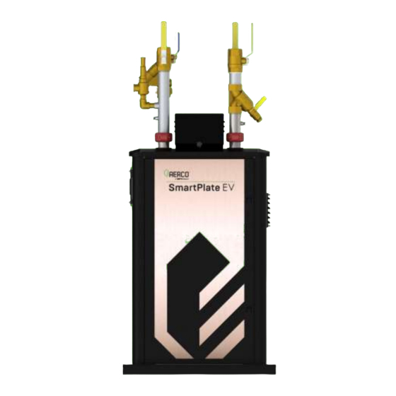
SmartPlate EV Installation, Operation and Maintenance Manual CHAPTER 1 – GENERAL INFORMATION 1.2 INTRODUCTION ® This manual provides detailed coverage for the AERCO SmartPlate EV line of Water-to-Water Heaters. All SmartPlate EV models are equipped with an Electronic Control System (ECS II) and an electronic 3-Way Control Valve. -
Page 7: Electronic Control System Ii (Ecs Ii)
SmartPlate EV Installation, Operation and Maintenance Manual CHAPTER 1 – GENERAL INFORMATION 1.3 ELECTRONIC CONTROL SYSTEM II (ECS II) All SmartPlate EV models contain identical Electronic Control Systems, referred to as ECS II. This system contains a Control Box, which includes all of the electronic circuitry for the ECS II. In addition, it includes several sensors and safety devices which provide temperature and flow control information to the Control Box circuitry, as shown below. -
Page 8: The Control Box Assembly
SmartPlate EV Installation, Operation and Maintenance Manual CHAPTER 1 – GENERAL INFORMATION The Control Box Assembly 1.3.1 The front panel on the Control Box contains the following components: • Temperature Controller: This device is the “brain” of the ECS II, processing data received from the temperature sensors. -
Page 9: Outlet Temperature Sensors
SmartPlate EV Installation, Operation and Maintenance Manual CHAPTER 1 – GENERAL INFORMATION Outlet Temperature Sensors 1.3.3 The Control System includes a Dual Temperature Sensor which is installed in the hot water outlet of the unit. This sensor contains two identical Type J thermocouples. The first thermocouple connects directly to the Temperature Controller to provide feedback PID control for the outlet water temperature. -
Page 10: Smartplate Ev Piping Assemblies
SmartPlate EV Installation, Operation and Maintenance Manual CHAPTER 1 – GENERAL INFORMATION 1.4 SmartPlate EV PIPING ASSEMBLIES All SmartPlate EV models include a 2” diameter piping assembly. This assembly includes the following components: • Flow Meter • Strainers (Boiler Water & DHW Sides) •... -
Page 11: 3-Way Electronic Control Valve
SmartPlate EV Installation, Operation and Maintenance Manual CHAPTER 1 – GENERAL INFORMATION 1.5 3-WAY ELECTRONIC CONTROL VALVE The 3-Way Electronic Control Valve is powered by 24 VAC from the ECS II Control Box. The Temperature Controller in the Control Box supplies a 4 to 20 mA control signal to precisely modulate the 3-Way Valve to accurately control the temperature of the DHW output to the desired setpoint. - Page 12 SmartPlate EV Installation, Operation and Maintenance Manual CHAPTER 1 – GENERAL INFORMATION (This Page Is Intentionally Blank) OMM-0147_C • SP-102 • 3/2/2021 Technical Support • (800) 526-0288 • Mon-Fri, 8 am - 5 pm EST Page 12 of 72...
-
Page 13: Installation
SmartPlate EV Installation, Operation and Maintenance Manual CHAPTER 2 – INSTALLATION INSTALLATION 2.1 INTRODUCTION All of the SmartPlate EV Water Heater models are shipped fully assembled and ready for installation. Therefore, installation will consist of the following tasks: • Unpack the SmartPlate EV Water Heater from its shipping container. •... -
Page 14: Site Selection And Preparation
SmartPlate EV Installation, Operation and Maintenance Manual CHAPTER 2 – INSTALLATION 2.3 SITE SELECTION AND PREPARATION Ensure that the site selected for installation of the SmartPlate EV Water Heater includes the following: • Access to AC input power at 120 VAC/60 Hz, 220 VAC/50 Hz or 220 VAC/60 Hz, single phase. -
Page 15: Setting The Unit
SmartPlate EV Installation, Operation and Maintenance Manual CHAPTER 2 – INSTALLATION Setting the Unit 2.3.2 The preferred way to lift and move the unit is to lift it with a forklift under the base. In multiple unit installations, it is important to plan the position of each unit in advance. Sufficient space for piping connections and future service/maintenance requirements must be taken into consideration. -
Page 16: Electrical Wiring Connections
SmartPlate EV Installation, Operation and Maintenance Manual CHAPTER 2 – INSTALLATION additional water from the boiler not required to maintain temperature is diverted back to the boiler via the 3-Way Electronic Control Valve. • Multiple SmartPlate EV installations: Remove the factory-installed plug from port B from at least one SmartPlate EV unit. - Page 17 SmartPlate EV Installation, Operation and Maintenance Manual CHAPTER 2 – INSTALLATION ELECTRICAL WIRING CONNECTIONS Instructions 3. Thread the power cable through the cut-out in the side of the Power Box. POWER CABLE ACCESS Figure 2.6-2, Power Cable Connection 4. Connect the power cable’s wires to the connectors in the Power Box as follows: BLACK CABLE - POWER WHITE CABLE - NEUTRAL GREEN CABLE - GROUND...
-
Page 18: Modbus Connection
SmartPlate EV Installation, Operation and Maintenance Manual CHAPTER 2 – INSTALLATION Modbus Connection 2.6.1 All SmartPlate EV Control Systems includes a Temperature Controller, which is equipped with a Communications Board that allows connection to Modbus networks. The required signal connections will depend on the ports available on the Energy Management System (EMS), Building Automation System (BAS), or Computer being used with the ECS II. -
Page 19: Pressure Relief Installation
SmartPlate EV Installation, Operation and Maintenance Manual CHAPTER 2 – INSTALLATION MODBUS WIRING CONNECTIONS Instructions Figure 2.6.1. Eurotherm 3504 Temperature Controller Terminal Connection Diagram 2.7 PRESSURE RELIEF INSTALLATION SmartPlate EV units are shipped with the Pressure Relief Valve assembled. Pressure Relief Valve and Air Bleeder Valve Installation Instructions 1. - Page 20 SmartPlate EV Installation, Operation and Maintenance Manual CHAPTER 2 – INSTALLATION Pressure Relief Valve and Air Bleeder Valve Installation Instructions 2. If the unit is being installed in New York City only in addition to the steps above you must install a second Relief Valve (P/N (kits 58202-2 or 58202-3) in the Boiler Water Intake Ball Valve/Strain combo, as shown in Figure 2.7-2.
-
Page 21: Functional Description
SmartPlate EV Installation, Operation and Maintenance Manual CHAPTER 3 – FUNCTIONAL DESCRIPTION FUNCTIONAL DESCRIPTION 3.1 INTRODUCTION SmartPlate EV Water Heaters are equipped with a double-wall, stainless steel brazed plate heat exchanger, an ECS II Electronic Control System, and a 3-Way Control Valve. This design results in a highly responsive system which provides virtually constant hot water flow at the selected setpoint temperature. -
Page 22: Over-Temperature Control And Safety Features
SmartPlate EV Installation, Operation and Maintenance Manual CHAPTER 3 – FUNCTIONAL DESCRIPTION The Controller continuously monitors the unit’s outlet temperature via a thermocouple located in the outlet port. The Controller also receives a feed-forward signal from the Flow Meter shown in the DHW inlet piping. - Page 23 SmartPlate EV Installation, Operation and Maintenance Manual CHAPTER 3 – FUNCTIONAL DESCRIPTION Figure 3.4. SmartPlate EV Water Heater Functional Block Diagram OMM-0147_C • SP-102 • 3/2/2021 Technical Support • (800) 526-0288 • Mon-Fri, 8 am - 5 pm EST Page 23 of 72...
- Page 24 SmartPlate EV Installation, Operation and Maintenance Manual CHAPTER 3 – FUNCTIONAL DESCRIPTION (This Page Is Intentionally Blank) OMM-0147_C • SP-102 • 3/2/2021 Technical Support • (800) 526-0288 • Mon-Fri, 8 am - 5 pm EST Page 24 of 72...
-
Page 25: Adjustment
SmartPlate EV Installation, Operation and Maintenance Manual CHAPTER 4 – ADJUSTMENT ADJUSTMENT 4.1 INTRODUCTION This chapter provides the adjustment procedures for the 3-Way Control Valve and the SmartPlate EV Electronic Control System (ECS II). Prior to shipment from AERCO, all 3-Way Control Valve Actuators are adjusted (auto-stroked) to ensure that they properly position the Control Valve from the fully-open to the fully-closed position. -
Page 26: 3-Way Control Valve Actuator Installation And Wiring
SmartPlate EV Installation, Operation and Maintenance Manual CHAPTER 4 – ADJUSTMENT 3-WAY Control Valve Actuator Installation and Wiring 4.2.1 If the 3-Way Control Valve Actuator needs to be replaced, follow the instructions below to install the new valve and wire it to the unit. 3-WAY CONTROL VALVE INSTALLATION AND WIRING Instructions 1. - Page 27 SmartPlate EV Installation, Operation and Maintenance Manual CHAPTER 4 – ADJUSTMENT 3-WAY CONTROL VALVE INSTALLATION AND WIRING Instructions Figure 4.2.1-3. Control Valve Installation 6. Connect the actuator’s Molex connector to the SmartPlate EV’s 3-circuit actuator connector. 7. Ensure that the valve’s DIP switches are in the positions shown below. The default setting of all DIP switches is: 1 = ON, 2 = ON, 3 = ON, 4 = OFF.
-
Page 28: 3-Way Valve Stroke Adjustment
SmartPlate EV Installation, Operation and Maintenance Manual CHAPTER 4 – ADJUSTMENT 3-Way Valve Stroke Adjustment 4.2.2 If necessary, the 3-Way Control Valve stroke can be adjusted as follows: 3-WAY CONTROL VALVE STROKE ADJUSTMENT Instructions 1. Apply power and wait for the LED to go off – approximately 10 seconds. 2. -
Page 29: Electronic Control System
SmartPlate EV Installation, Operation and Maintenance Manual CHAPTER 4 – ADJUSTMENT 4.3 ELECTRONIC CONTROL SYSTEM The SmartPlate EV Electronic Control System (ECS II) is preset at the setpoint temperature specified on the Sales Order. The over-temperature alarm limit is normally set 20°F above the specified setpoint. - Page 30 SmartPlate EV Installation, Operation and Maintenance Manual CHAPTER 4 – ADJUSTMENT 4. Two seconds after the ▲ or ▼ arrow button is released, the display will blink to indicate that the Temperature Controller has accepted and stored the displayed value. Figure 4.3.1.
-
Page 31: Over-Temperature Alarm Limit Adjustment
SmartPlate EV Installation, Operation and Maintenance Manual CHAPTER 4 – ADJUSTMENT SETPOINT TEMPERATURE ADJUSTMENT Instructions Run/Hold button Not used for ECS II application Press Page button to select a new list of Page button parameters Press Scroll button to select a new parameter in a Scroll button list Press to decrease the value shown in the lower... - Page 32 SmartPlate EV Installation, Operation and Maintenance Manual CHAPTER 4 – ADJUSTMENT OVER-TEMPERATURE ALARM LIMIT ADJUSTMENT Instructions 11. To exit the programming mode, press the SET and ▼ buttons simultaneously, or simply wait one minute and the display will automatically exit the programming mode. 12.
-
Page 33: Operation
SmartPlate EV Installation, Operation and Maintenance Manual CHAPTER 5 – OPERATION OPERATION 5.1 INTRODUCTION This chapter provides the pre-operational checks, initial start-up and operating procedures for SmartPlate EV Water Heaters. CAUTION! Do NOT operate equipment exceeding design conditions as specified on the nameplate. SmartPlate EV Water Heaters must never be subjected to pressure greater than the maximum differential pressure specified on the nameplate. -
Page 34: Shutting Down The System
SmartPlate EV Installation, Operation and Maintenance Manual CHAPTER 5 – OPERATION PRE-OPERATION CHECKS AND INITIAL START-UP Instructions 7. When in the Manual mode, the upper display will continue to show the current outlet water temperature of the heater. The lower display will show the position of the Control Valve Actuator in %. - Page 35 SmartPlate EV Installation, Operation and Maintenance Manual CHAPTER 5 – OPERATION Instructions SHUTTING DOWN THE SYSTEM ISOLATION VALVES BOILER WATER ISOLATION VALVES STRAINER DOMESTIC WATER STRAINER RELIEF VALVE AIR PLUGS Figure 5.3. Typical SmartPlate EV Piping 7. To place the unit back in service, fill the unit and perform the pre-operational checks and start-up procedures described in Sections 5.2 and 5.3.
- Page 36 SmartPlate EV Installation, Operation and Maintenance Manual CHAPTER 5 – OPERATION (This Page Is Intentionally Blank) OMM-0147_C • SP-102 • 3/2/2021 Technical Support • (800) 526-0288 • Mon-Fri, 8 am - 5 pm EST Page 36 of 72...
-
Page 37: Scheduled Maintenance
SmartPlate EV Installation, Operation and Maintenance Manual CHAPTER 6 – SCHEDULED MAINTENANCE SCHEDULED MAINTENANCE 6.1 INTRODUCTION SmartPlate EV Water Heaters require regular routine maintenance to keep the unit operating at optimum efficiency. AERCO recommends that the tasks listed in Table 6-1 – Scheduled Maintenance Action, be performed at the periodic intervals specified. -
Page 38: Over-Temp Switch Check
SmartPlate EV Installation, Operation and Maintenance Manual CHAPTER 6 – SCHEDULED MAINTENANCE PLATE PACK LEAKAGE CHECKS Instructions 3. If there is no evidence of leakage, reinstall the thermal jacket on the Plate Pack and return the unit to service use. 6.3 OVER-TEMP SWITCH CHECK Once every 3 months, check the Over-Temp switch located in the ECS II Control Box as follows:... -
Page 39: 3-Way Control Valve Operational Check
SmartPlate EV Installation, Operation and Maintenance Manual CHAPTER 6 – SCHEDULED MAINTENANCE 6.5 3-WAY CONTROL VALVE OPERATIONAL CHECK Refer to Chapter 4, Section 4.2 and recalibrate the 3-Way Control Valve. Also, check the LED indicator to ensure the Valve is functioning correctly. NOTE: To avoid repeated draining of the Water Heater, perform the annual scheduled maintenance checks specified in section 6.9 at the same time. -
Page 40: Periodic Cleaning Of Heat Exchanger
SmartPlate EV Installation, Operation and Maintenance Manual CHAPTER 6 – SCHEDULED MAINTENANCE SENSOR CHECKS Instructions 7. On the flow meter, remove the U-Clip from the retaining slot on the tee. Examine the sensor body for scale. Check the paddlewheel for free spin by blowing lightly on the rotor. Take extreme caution to avoid dropping or otherwise damaging the paddlewheel while out of the assembly piping. -
Page 41: Troubleshooting
SmartPlate EV Installation, Operation and Maintenance Manual CHAPTER 7 – TROUBLESHOOTING TROUBLESHOOTING 7.1 INTRODUCTION The troubleshooting procedures provided in this chapter are intended to aid service and maintenance personnel in isolating the most probable cause of a fault in a packaged SmartPlate EV Water Heater. - Page 42 SmartPlate EV Installation, Operation and Maintenance Manual CHAPTER 7 – TROUBLESHOOTING TROUBLESHOOTING PROCEDURES Instructions 5. Refer to the applicable procedures in Chapter 8 – Corrective Maintenance if component removal and/or replacement is required. TABLE 7-1. Troubleshooting – Control Valve and Piping Assembly Fault Indication Probable Cause Corrective Action...
- Page 43 SmartPlate EV Installation, Operation and Maintenance Manual CHAPTER 7 – TROUBLESHOOTING TABLE 7-1. Troubleshooting – Control Valve and Piping Assembly Fault Indication Probable Cause Corrective Action (Continued) 5. Control Valve is not 5. Check Auto-Stroke to make sure the opening properly. actuator is traveling throughout the complete 90°...
- Page 44 SmartPlate EV Installation, Operation and Maintenance Manual CHAPTER 7 – TROUBLESHOOTING TABLE 7-2. Troubleshooting – Electronic Control System (ECS II) Fault Indication Probable Cause Corrective Action Temperature Controller is 1. Circuit breaker tripped 1. Reset the circuit breaker on the 24 VAC ON, but Temperature step-down transformer.
- Page 45 SmartPlate EV Installation, Operation and Maintenance Manual CHAPTER 7 – TROUBLESHOOTING TABLE 7-2. Troubleshooting – Electronic Control System (ECS II) Fault Indication Probable Cause Corrective Action Outlet water temp. far 1. Incorrect Temperature 1. Refer to Chapter 4 and check the current below Setpoint Controller setting setting of Over-Temp switch.
- Page 46 SmartPlate EV Installation, Operation and Maintenance Manual CHAPTER 7 – TROUBLESHOOTING TABLE 7-3. Troubleshooting Guide for Temperature Control Issues Observation Probable Cause Corrective Action Too many valve Low flow condition may be Increase the Proportional value (Pb oscillations or too wide unsteady or at a critical and/or Pb2).
-
Page 47: Corrective Maintenance
SmartPlate EV Installation, Operation and Maintenance Manual CHAPTER 8 – CORRECTIVE MAINTENANCE CORRECTIVE MAINTENANCE 8.1 INTRODUCTION This chapter provides the procedures to correct and repair faults detected during operation or isolated during troubleshooting of SmartPlate EV Water Heaters. The procedures in this chapter are divided into two sections: •... -
Page 48: Heat Exchanger Cleaning And De-Scaling
SmartPlate EV Installation, Operation and Maintenance Manual CHAPTER 8 – CORRECTIVE MAINTENANCE DHW OUTLET BOILER WATER DHW INLET BOILER WATER OUTLET INLET ISOLATION BALL VALVES ISOLATION BALL VALVES BLOW-DOWN VALVE PRESSURE RELIEF VALVE BLOW-DOWN VALVE 3-WAY CONTROL VALVE LEFT-FRONT VIEW RIGHT-FRONT VIEW Figure 8.2.1. - Page 49 SmartPlate EV Installation, Operation and Maintenance Manual CHAPTER 8 – CORRECTIVE MAINTENANCE HEAT EXCHANGER REPLACEMENT Instructions 4. Connect a hose to the Strainer on the Boiler Water side of the piping assembly. Open the valve on the Strainer and drain the boiler water from the unit. It will be necessary to loosen a Victaulic coupling by the heat exchanger to allow air into the pipe during draining.
-
Page 50: Control Valve Actuator Replacement And Valve Removal
SmartPlate EV Installation, Operation and Maintenance Manual CHAPTER 8 – CORRECTIVE MAINTENANCE CONTROL VALVE ACTUATOR REPLACEMENT AND VALVE REMOVAL 8.2.2 The only replaceable item on the 3-Way Control Valve is the Electronics Module. The procedures for removing this Module or replacing the complete Control Valve are provided in Sections 8.2.2.1 and 8.2.2.2 below. - Page 51 SmartPlate EV Installation, Operation and Maintenance Manual CHAPTER 8 – CORRECTIVE MAINTENANCE 3-WAY CONTROL VALVE REPLACEMENT Instructions ISOLATION BALL ISOLATION BALL VALVES (2) VALVES (2) BLOW-DOWN VALVE (Connect Drain Hose Here) 3-WAY CONTROL VALVE Figure 8.2.2.1. Control Valve Replacement – Rear View 5.
-
Page 52: Strainers
SmartPlate EV Installation, Operation and Maintenance Manual CHAPTER 8 – CORRECTIVE MAINTENANCE STRAINERS 8.2.3 All SmartPlate EV Water Heater models utilize a combination strainer and ball valve on the boiler side, and a strainer on the DHW side to prevent fouling of the heat exchanger by trapping foreign material before it enters the unit. -
Page 53: Electronic Control System (Ecs Ii)
SmartPlate EV Installation, Operation and Maintenance Manual CHAPTER 8 – CORRECTIVE MAINTENANCE 8.3 Electronic Control System (ECS II) WARNING! Turn off the Control Box’s power switch and disconnect AC power prior to performing all corrective maintenance procedures in the sections below. Failure to observe this warning may result in serious personal injury CONTROL BOX ASSEMBLY COMPONENTS 8.3.1... -
Page 54: Over-Temperature Switch Replacement
SmartPlate EV Installation, Operation and Maintenance Manual CHAPTER 8 – CORRECTIVE MAINTENANCE OVER-TEMPERATURE SWITCH REPLACEMENT 8.3.3 The Over-Temperature switch generates an alarm when the preset temperature limit is exceeded. Complete the instructions below to removal and replacement it. TEMPERATURE CONTROLLER OVER TEMPERATURE SWITCH... -
Page 55: Appendix A - Modbus Control And Communication
SmartPlate EV Installation, Operation and Maintenance Manual APPENDIX A – MODBUS CONTROL AND COMMUNICATION APPENDIX A Modbus Control and Communication – TEMPERATURE CONTROLLER (Eurotherm 3504) PROCEDURES MODBUS COMMUNICATION INFORMATION & PROCESS / DIAGNOSTIC ALARM MESSAGES OMM-0147_C • SP-102 • 3/2/2021 Technical Support •... - Page 56 SmartPlate EV Installation, Operation and Maintenance Manual APPENDIX A – MODBUS CONTROL AND COMMUNICATION A.1 Temperature Controller Procedures – Eurotherm 3504 The following sections provide the procedures to add a Modbus Communication board to the Temperature Controller and change communication addresses. A.1.1 Replacing the Communication Board in the Temperature Controller Parts Needed: a.
- Page 57 SmartPlate EV Installation, Operation and Maintenance Manual APPENDIX A – MODBUS CONTROL AND COMMUNICATION REPLACING THE COMMUNICATION BOARD Instructions COMMUNICATIONS BOARD Figure A.1.1-3 4. Place Temperature Controller back into Control Box and power up unit. A.1.2 Changing the Temperature Controller’s Communication Addresses The Temperature Controller’s factory-default address is 51.
- Page 58 SmartPlate EV Installation, Operation and Maintenance Manual APPENDIX A – MODBUS CONTROL AND COMMUNICATION A.2 Changing the Baud Rate To change the baud rate, proceed as follows: 1. Hold down the PAGE button until the following screen appears Figure A.2-1: Changing Baud Rate Screen 2.
- Page 59 SmartPlate EV Installation, Operation and Maintenance Manual APPENDIX A – MODBUS CONTROL AND COMMUNICATION A.3 Modbus Communication Information NOTE: The Temperature Controller supports the MODBUS RTU mode of transmission. The default settings are: 19200 Baud Rate, one start bit, eight data bits, one stop bit, & no parity bit. TEMPERATURE CONTROLLER MODBUS POINTS MODBUS Menu...
- Page 60 SmartPlate EV Installation, Operation and Maintenance Manual APPENDIX A – MODBUS CONTROL AND COMMUNICATION Alarm Descriptions: • Alarm 1: Over temperature – DHW Outlet temperature is above set Over Temp Alarm temperature • Alarm 2: Outlet temperature not meeting DHW setpoint (DHW Out<DHW STPT for 10 minutes) •...
- Page 61 SmartPlate EV Installation, Operation and Maintenance Manual APPENDIX A – MODBUS CONTROL AND COMMUNICATION DIAGNOSTIC ALARMS DISPLAY MEANING WHAT TO DO` EE.Er Electrically Erasable Memory This fault will automatically take you into Error: The value of an Configuration level. Check all of the configuration operator, or configuration, parameters before returning to Operator level.
- Page 62 SmartPlate EV Installation, Operation and Maintenance Manual APPENDIX A – MODBUS CONTROL AND COMMUNICATION DIAGNOSTIC ALARMS DISPLAY MEANING WHAT TO DO` This error may result from no power to the Flow Meter (check for green power light on rear of meter Secondary Input Missing or O PEn or 0-5V Flow Meter signal connections), or a...
-
Page 63: Appendix B - Schematic
SmartPlate EV Installation, Operation and Maintenance Manual APPENDIX B –SCHEMATIC APPENDIX B SCHEMATIC – SmartPlate EV Schematic, 68107 rev B OMM-0147_C • SP-102 • 3/2/2021 Technical Support • (800) 526-0288 • Mon-Fri, 8 am - 5 pm EST Page 63 of 72... - Page 64 SmartPlate EV Installation, Operation and Maintenance Manual APPENDIX B –SCHEMATIC (This Page Is Intentionally Blank) OMM-0147_C • SP-102 • 3/2/2021 Technical Support • (800) 526-0288 • Mon-Fri, 8 am - 5 pm EST Page 64 of 72...
-
Page 65: Appendix C - Smartplate Ev Part Lists
SmartPlate EV Installation, Operation and Maintenance Manual APPENDIX C – PART LISTS APPENDIX C SMARTPLATE EV PART LISTS – TABLE C-1: Top Level Part Number TABLE C-2: Exterior Panel Part Numbers Part # Pressure Description Item # Part # Description 37173 Front Side Upper Rail 29519-1... - Page 66 SmartPlate EV Installation, Operation and Maintenance Manual APPENDIX C – PART LISTS TABLE C-3: Piping-Heat Exchanger Part # Part # Description 22420-1 30 Plate Piping & Heat Exchanger Assy, 150 psi 22420-2 40 Plate Piping & Heat Exchanger Assy, 150 psi 22420-3 30 Plate Piping &...
- Page 67 SmartPlate EV Installation, Operation and Maintenance Manual APPENDIX C – PART LISTS TABLE C-6: Additional Parts Item Part # Qty Description Item Part # Qty Description 69369 Control Box – See Table C-7 80129 Top Insulation 65249-1 Paddlewheel Flow Sensor 200 psi 80130-TAB Insulation Wrap 65249-2...
- Page 68 SmartPlate EV Installation, Operation and Maintenance Manual APPENDIX C – PART LISTS TABLE C-7: Ventilation, Pressure Relief Valve, Controller Part Numbers Item Part # Qty Description Item Part # Qty Description 69180 EBM Mini Fan Guard 93451 Nipple, 3/4" 65246 24V DC Fan 30195 Control Panel...
- Page 69 SmartPlate EV Installation, Operation and Maintenance Manual APPENDIX C – PART LISTS TABLE C-8: Wiring Harness Part Numbers Part # Description 63347 Main Harness 63348 Eurotherm DC Harness 63349 Power Harness, 120 VAC 63351 Power Harness, Eurotherm 63352 Power Harness, Overtemp 63354 Fan Power Harness 63357...
-
Page 70: Appendix D - Recommended Spare Parts
SmartPlate EV Installation, Operation and Maintenance Manual APPENDIX D – RECOMMENDED SPARE PARTS APPENDIX D RECOMMENDED SPARE PARTS – NOTE Refer to the SmartPlate Parts List illustrations in Appendix C for the locations of the recommended spare parts listed below. SmartPlate EV Recommended Emergency Spare Parts DESCRIPTION PART NUMBER... - Page 71 SmartPlate EV Installation, Operation and Maintenance Manual NOTES: OMM-0147_C • SP-102 • 3/2/2021 Technical Support • (800) 526-0288 • Mon-Fri, 8 am - 5 pm EST Page 71 of 72...
- Page 72 SmartPlate EV Installation, Operation and Maintenance Manual Change Log Date Description Changed By Rev B: Added model SPDW-EV140. Moved Temp Controller P/N to Table C-9 in Appendix C. 2/16/2021 Chris Blair Revised list of Recommended Spare Parts in Appendix D. Updated schematic, Appendix B.
Need help?
Do you have a question about the Aerco SmartPlate EV and is the answer not in the manual?
Questions and answers