Table of Contents
Advertisement
Quick Links
Advertisement
Table of Contents

Subscribe to Our Youtube Channel
Related Manuals for Nokeval FD100A4-2012


Summary of Contents for Nokeval FD100A4-2012
- Page 1 Nokeval FD100A4-2012 and FD100A6- 2012 large field displays User Manual...
-
Page 2: Table Of Contents
Contents Document information ............................2 FD100A4 and FD100A6 field displays ........................ 3 Power supply connection ..........................4 Configuring ................................ 5 Specifications ..............................21 Document information Device Scope: FD100A4 (4-digit device) FD100A6 (6-digit device) Document ID: 13992 Document Version: Document Date: 2.7.2024... -
Page 3: Fd100A4 And Fd100A6 Field Displays
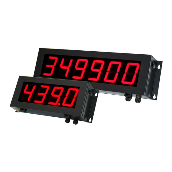
FD100A4 and FD100A6 field displays Introduction The FD100 series includes 4 and 6 digit models. Digit size is 100mm. The displays are based on input cards of the panel meter series 2000 giving over 100 combinations. The unit has wide power supply range of 41...265 VAC or 20...28 VAC/VDC depending on model. -
Page 4: Power Supply Connection
Power supply connection The unit has wide power supply range of 41...265 VAC or 20...28 VAC/VDC depending on model. There are two types of power supply connectors; grey connector color is used to indicate higher voltages and green color to indicate 24 V. FD100A4-F48/230 and FD100A6-F48/230 Power supply 41...265 VAC... -
Page 5: Electronics Unit
Cards Configuring The display unit is configured with the small display and buttons inside the main case. The display can be configured with many ways: • By using the front panel display and buttons. Using the buttons is described in chapter User interface. •... -
Page 6: Operator Menu
• Normal state – indicating readings. • Operator menu – adusting the alarm levels. • Configuration state – changing the configuration settings. • Monitor state – indicating troubleshooting readings. Normal state and the indicator LEDs After switching the power on, the user interface is in normal state, indicating readings. There is three modes for the normal state, selected in the Master configuration menu, item Gen/Mode: •... - Page 7 Configuration state Entering In the normal state, press the * and ▲ buttons together two seconds. Enter with the ▶ button. The contents of the menu depend on the card type installed, and is described in Select the slot to be configured using the ▲▼ buttons. The options are Master, Slot A, Slot B, and Slot C. the chapter of that card type.
- Page 8 Exiting When all is done for this slot, exit from the menu with * button. Select ▲▼ Save (keep the changes) or Undo (discard the changes) and press *. You will be in the slot selection menu. Select another slot or exit with * button.
- Page 9 Gen/Mode The display mode in the normal state. The options are described above in section Normal state and the indicator LEDs. Gen/Ch The channel to be displayed in the Single mode. The channels are: • 1 = slot A reading •...
-
Page 10: Jumper Configurations
• Sqrt: Square root from the channel selected with From1. A negative value will give negative results. Tip: a square of the value can be calculated by selecting Mul operation and setting From1=From2. Math/Dec The number of decimals to be displayed on the math channel. Master monitor menu Mainch The channel being displayed. -
Page 11: Operation
Input card 2012-IN Jumpers The jumpers are set in factory and there is no need to alter them. The correct positions are shown in the picture. Connections A voltage or a current signal can be connected in the input card but not both. A voltage signal is connected in terminals 4+ and 3-. -
Page 12: Configuration Menu
The reading is scaled using up to ten user-entered scaling points Mea/Sca to a scaled (engineering) reading. If the tare function is active, the current tare value is subtracted. The current value is copied to the tare value memory when a switch programmed as a tare switch is activated. The tare value is stored in an EEPROM memory and is retained even if the power supply is cut off. - Page 13 Mea2 = 20 (mA) Sca2 = 100 (scaled) A non-linear behaviour is obtained by using more than two points. The points can be used freely, but the Mea settings must be in ascending order: Mea1 is smaller than Mea2 etc. If a Lock command is given to a Mea setting (Mekuwin: L button, user interface: see chapter User interface), the current unscaled reading is copied to the value of this Mea setting.
-
Page 14: Monitor Menu
• ExtSw: An external contact connected in slot A works as a hold switch. • Both: Both of the above switches work. While the hold switch is active, the reading is locked and keeps the same value. In/Tare/Act Tare switch selection: •... - Page 15 Output card 2000-OUT Connections The analog output card provides one mA or V output signal. These cannot be used at the same time. The analog output card can be installed in slots B or C or both. An active mA output is provided in terminals 4+ and 5-. Voltage output is in terminals 6+ and 5-.
- Page 16 Out/Rdg and Out The scaling of the output. When the reading corresponds to Rdg1, the analog output will be Out1 mA or V. Likewise, when the reading corresponds to Rdg2, the output will be Out2. Between and outside these points, linear interpolation is used. How to scale a reading 0-100 to 4-20mA output: Range = mA Rdg1 = 0...
- Page 17 Serial card 2000-RS Jumpers The serial communications card 2000-RS works most often with the factory set jumpers: no termination. But if the RS-485 bus is long (>50 m), the last device on the bus should be terminated. If there is no devices giving the small voltage between the lines when no-one is transmitting, calling fail- safe, this device can be jumpered to do that.
- Page 18 Will be increased by one every time a valid serial bus command is processed. Will roll over to 0 after 255. SCL protocol A more detailed document of the Nokeval SCL protocol is available on Nokeval WWW pages. This device accepts the following SCL commands: TYPE ? Returns the type and firmware version: ”2012 V1.5”...
- Page 19 Relay card 2000-REL2 2000-REL2 is an alarm relay card with 2 relays. The card can be installed in slots B and C or both. If the device is to be equipped with one relay card, it should be installed in slot C. Connections Two relay card 2000-REL2 The picture shows the relay contacts in the normal or passive state.
- Page 20 Only in firmware V1.0-1.2. Defines the time how long the alarm condition must be true before the alarm will actually activate. This is set in samples – one sample corresponds to 1/15 second. This is used to prevent short disturbances from triggering the alarm. This applies to the alarm deactivation too, except when the alarm has been programmed to be manually reset.
-
Page 21: Specifications
Specifications Enclosure Indoors installation Dimensions Allowed See page 3 Outdoors installation Allowed Protection IP65 Altitude Max 2000 m Pollution degree Operating temperature -10…+50 °C Weight, 4 digits 5 kg Storage temperature -30…+50 °C Weight, 6 digits 6 kg Humidity < 90 %Rh Power supply Nominal voltage 20…28 VAC / VDC or... - Page 22 2000REL2: 2 pcs Alarms 1 per relay Contacts 250 VAC 2 A resistive loadL Snubber An external one must be used when driving heavily inductive loads Nokeval Nokeval Oy, Yrittäjäkatu 12, 37100 Nokia, Finland, Tel. +358 3424800, fax. +358 3422066, sales@nokeval.com, www.nokeval.com...
Need help?
Do you have a question about the FD100A4-2012 and is the answer not in the manual?
Questions and answers