Table of Contents
Advertisement
Quick Links
Advertisement
Table of Contents

Subscribe to Our Youtube Channel
Related Manuals for Nokeval 2041


Summary of Contents for Nokeval 2041
- Page 1 Nokeval No 270503 User's Manual Model 2041 for strain gauge sensors...
-
Page 2: Table Of Contents
Serial communication ........................12 Serial protocol (SCL) ........................12 Secret code ........................13 Panelmeter 2000 construction ..................14 Modular indicator series 2000 ..................15 Manufacturer: Nokeval Oy Yrittajakatu 12 FIN-37100 NOKIA Tel. +358 3 342 4800 Fax. +358 3 342 2066... -
Page 3: Alarm Relays
• Power supply 85..240 VAC or 12..32 VDC/ 24 VAC galvanically isolated from input and output. Analog The versatile panelmeter 2041 is designed for strain gauge sensors. Strain gauge sensors can be connected with 4 or 6 conversion is done by a 16-bit AD-converter (resolution 1/ wires. -
Page 4: General
Accuracy 0,05% of the scaled display range Galvanic isolation test voltage 2000 VDC Load resistance maximum 700W How to order 2041-OUT- REL2-24VDC Alarms (option): Type Relays 2..4 alarm relays, max 230 VAC / 2A Output OUT Optional cards 2000-REL2 or 2000-... -
Page 5: Terminal Connections
87,5 ohm load to 10 V exitation voltage. Half bridge connection: Model 2041 accepts also half bridge sensor. This is Half bridge connection in below picture. Terminal 3 is an optional function which must be specified when not connected. -
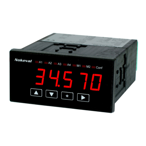
Page 6: Front Panel And Keys
Front panel and keys Conf-light indicates program stage Alarm lights A1 and A2 5620.0 With -keys You can move on or change numbers and values in programming menu. Accptance of chosen stage of program Setting of alarms Display Tare procedure: By first pressing of key you can see setpoint of Press and hold right arrow (>) until display shows... -
Page 7: Configuration
Configuration level with key. You may set alarms in configuration You can enter configuration state by pressing two or in display stage. Alarm levels can be set in configu- seconds keys at same time. By arrow keys ration state or measuring state. You can cancel changes you can move upwards and downwards in main menu. -
Page 8: Configuration Parameters
Configuration parameters Halt Sense Display can be set to show zero below Halt value e.g. Typical sensor sensivity is 2 mV/V which you will find the display should be showed zero when weighing in label of sensors. Change SET value according to value is under 10, set halt value 10. - Page 9 Scaling of display Display can be scaled on two different ways. Select LOAD in menu and press -key. SET: Enter display value on max.loading signal from bridge. Example: If sensor gives 2 mV/V and supply voltage for sensor is 10 V, max signal from bridge is 2 mV/V x 10V = 20 mV.
-
Page 10: Output 0/4-20 Ma And 0
Output 0/4-20 mA and 0..10 V (option) The display may be provided with isolated output, bration is needed in configuration. You need not select ranges 0..20 mA, 4..20 mA or 0..10 V, which are card in programming because meter recognizes the programmable. -
Page 11: Alarm (Option)
Alarm (option) Meter may be provided optional alarm relay card relay direction. When all alarm settings is done in (2000-REL2). In REL2 card is two relays with change configuration mode, alarm levels can be easily changed over contact. Both relays can be setting in configura- with frontpanel keys in normal measuring state. -
Page 12: Serial Output Rs-485/Rs-232 (Option)
Serial output RS-485/RS-232 (option) In config state you can first select card type (serial) Meter may be provided with optional serial output and mounted to slot B or C and then address and Baud you can read measurements by e.g. PC. Display rate. -
Page 13: Serial Communication
Serial protocol (SCL) calculation) MESSAGES: When asking the measurement data ?<ETX> <BCC> from the panelmeter 2041 through the serial port, a 4Dx45x41x20x43x48x20x31x20x3F x03 = 6F command sequence which is in accordance with the SCL protocol is used for the inquiry. -
Page 14: Secret Code
Secret code You can enter secret code by pressing six time keys from left to right 1,2 3,4 in order to help recording and (1-4) in wished order (lines goes forward in display). remembering. Setting must be repeated in same order before new e.g. -
Page 15: Panelmeter 2000 Construction
Panelmeter 2000 construction second relay card into slot B. If you The 2000 series panelmeters are modular and easy to accept only closing or opening relay contacts, you assemble. According to customers wishes. The basic need only one relay card with 4 relays placed into slot construction consists of mother board with tree slots, C.
Need help?
Do you have a question about the 2041 and is the answer not in the manual?
Questions and answers