Table of Contents
Advertisement
Quick Links
Advertisement
Table of Contents

Related Manuals for JLG POWER TOWERS Pecolift


Summary of Contents for JLG POWER TOWERS Pecolift
- Page 1 Pecolift Operating and Maintenance Manual...
-
Page 2: Table Of Contents
CONTENTS CONTENTS INTRODUCTION Introduction The Pecolift (referred to as “the machine” in this manual) is a simple, safe and efficient alternative to step-ladders, platform/podium steps and small scaffold Operating Specifications towers. It is the first non-powered, powered access platform. It does not require batteries (or charging) or connection to an electricity supply. -
Page 3: Operating Specifications
OPERATING SPECIFICATIONS OPERATING SPECIFICATIONS Working Dimensions Maximum working height: 3.50 m Maximum platform height: 1.50 m Platform dimensions: 720 mm (L) x 600 mm (W) Working footprint: 985 mm x 700 mm Safe working load: 150 kg (1 person + tools) Maximum manual force: 200 N Maximum gradient for operation:... -
Page 4: Do's And Don'ts
DO’S and DON’TS DO’S DON’TS 1. Read, understand and adhere to the instructions on the machine 1. Never exceed the safe working load 150kg (1 person plus tools). and in the Instruction Guide or Operating Manual. 2. Never use the machine as a goods lift or crane. 2. -
Page 5: Primary Components
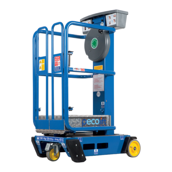
PRIMARY COMPONENTS PRIMARY COMPONENT LOCATIONS Tool Tray Flywheel Handle Flywheel Gates Platform Tray Emergency Spirit Lowering Tool Level Swivel Auto-Lok Castor Rubber Foot (Pad) Braked Wheel... -
Page 6: Operating Procedures (Incl. Emergency Operation)
OPERATING PROCEDURES OPERATING PROCEDURES It is the owners and/or the users responsibility to ensure that the machine is maintained and operated in accordance with the operation and maintenance procedures contained within this manual. It is essential to be familiar with the correct operating procedures. The operator must have adequate training for this type of platform. - Page 7 OPERATING PROCEDURES PRE-OPERATION CHECKS 1. Visually inspect the machine for any signs of damage to handrails, platform tray, chassis and mast lifting structure including mast fixing bolts. 2. Check castor and wheels rotate freely and are undamaged. 3. Check castor axle bolt (Pic 1) and wheel split pins (Pic...
- Page 8 OPERATING PROCEDURES EMERGENCY LOWERING OPERATION Never attempt to recover the machine/operator if there is any possibility the machine is contacting any live wiring/cabling and is therefore potentially ‘live’ . Never operate the emergency lowering without a person in the platform otherwise serious injury may result. The Emergency Lowering Procedure is for lowering the platform from height with an incapacitated operator in the platform and for no other purpose.
-
Page 9: Daily Maintenance
MAINTENANCE PROCEDURES Please note that whilst the machine is extremely simple to 2. Check that the guardrails are not damaged and all fixings are secure. maintain, all work must be carried out by a competent person. 3. Check gates and gate hinges are secure and gates fully self close NOTE: PUWER (The Provision and Use of Workplace Equipment when released. - Page 10 MAINTENANCE PROCEDURES SIX MONTHLY CHECKS - LOLER Minor scuffing and wear of the belt surfaces, and visible steel 1. In order to inspect the internal mechanisms of the machine the braided wires, is acceptable. However, there must be no signs of following covers must be removed;...
- Page 11 MAINTENANCE PROCEDURES 3-4mm Minimum Clearance.
- Page 12 MAINTENANCE PROCEDURES 6. Ensure platform entrance gates open and close freely and that 13. Check all instruction labels are present and clear. Refer to the key they self-close when released. Check pivots and springs for signs spare parts. Check aluminium specification plate is clear and of fatigue and damage.
-
Page 13: Lubrication Of Castor Mounting Plate
LUBRICATION OF CASTOR MOUNTING PLATE LUBRICATION OF CASTOR MOUNTING PLATE CASTOR MOUNTING PLATE LUBRICATION 2. Now release the castor latch which is situated underneath Tools required: the platform, within the picture Small Tin of Copper Slip (500mg) you can see the desired Small Paint Brush position of the latch to show it is released and castor is fully... -
Page 14: Maintenance Frequency Summary
MAINTENANCE FREQUENCY SUMMARY MAINTENANCE FREQUENCY SUMMARY The table below summarises the frequency of checks that must be carried out on the machine, as detailed on pages 9 to 13. MAINTENANCE FREQUENCY TABLE Item Daily Monthly 6 Monthly (LOLER) Wheels, Castor & Rubber Feet Guardrails Gates Spirit Level... -
Page 15: Transport Instructions
TRANSPORTATION, LOADING, TOWING, MANOEUVRING AND STORAGE TRANSPORT INSTRUCTIONS Use at least two straps, with one strap over the chassis, around the mast section and out to the rear of the machine. The other strap should be fed through the front of the chassis and the straps taken It is the responsibility of the transport driver to ensure the machine is forward, so that the machine is tied down in four diagonal directions. - Page 16 TRANSPORTATION, LOADING, TOWING, MANOEUVRING AND STORAGE HOW TO MANOEUVRE Ensure the platform is fully lowered to the transport position and wheel onto the tail lift bed. Once correctly positioned on the bed, lock the swivel castor brake. STORAGE Raise the tail lift to the vehicle bed height. Unlock the castor and manoeuvre to the desired location on the vehicle and tie down as described above.
-
Page 17: Key Spare Parts
KEY SPARE PARTS Part No. Wheel/Brake Sprocket PEL-M-400 Swivel Castor PEL-M-401 Spirit Level PT-M-106 Gates (pair) PEL-M-402 Corner Foot (Pad) PEL-M-403 Mudguard PEL-M-404 Tool Tray PEL-M-405 Decal Set 1 PEL-M-600 Decal Set 2 (Pecolift) PEL-M-602 Chassis Cover PEL-M-406 Emergency Lowering Tool PEL-M-407 Handle cover PEL-M-408... -
Page 18: Decal Placement
DECAL PLACEMENT... - Page 19 DECAL PLACEMENT Picture Description Decal Location 5 kg Maximum load, x 2 Inside toolbox, 1 in each pocket Do not tie down over guardrails, x 4 Each side of cage near gates, upper and middle guardrails Safe Working Load 150 kg Chassis gate end Lifting/tie down point, x 2 Front of chassis, next to lifting/tie down points...
-
Page 20: Warranty Terms
WARRANTY TERMS WARRANTY IMPORTANT Your Pecolift or Pecolift WR (The Machine) is covered by a parts and Warranty may, at the sole discretion of the Manufacturer, be voided if components warranty as stated in the purchase terms and conditions. the scheduled service/inspections are not carried out in accordance with this manual. -
Page 21: Declaration Of Conformity
DECLARATION OF CONFORMITY... -
Page 22: Appendix 'A' - Operating Specifications For Pecolift Wr
APPENDIX ‘A’ - OPERATING SPECIFICATIONS FOR PECOLIFT WR OPERATING SPECIFICATIONS FOR WIND RATED MACHINE DO’S DON’TS 1. Read, understand and adhere to the 1. Never exceed the safe working load 150kg Working Dimensions instructions on the WR machine and in the (1 person plus tools). -
Page 23: Appendix 'B' - Operating And Safety Instructions For Pecolift Wr
APPENDIX ‘B’ - OPERATING AND SAFETY INSTRUCTIONS FOR PECOLIFT WR OPERATING PROCEDURES NORMAL OPERATION It is the owners and/or users responsibility to ensure that the 1. The WR machine must only be used on hard surfaces not sloping Pecolift WR (referred to as “the WR machine” in this manual) is more than 3°. -
Page 24: Appendix 'C' - Additional Maintenance Instructions For Pecolift Wr
APPENDIX ‘C’ - ADDITIONAL MAINTENANCE INSTRUCTIONS FOR PECOLIFT WR FITTING PROCEDURE FOR PT-M-102 REPLACEMENT CASTOR AND FIXINGS KIT Important. These instructions apply to all WR machines Kit comprises of; BEFORE Serial no. 36312615G. 1 x Castor with M12x60 Hex head bolt 10.9 BZP 1 x M12 Nyloc nut grade 10 BZP CASTOR SAFETY &... - Page 25 APPENDIX ‘C’ - ADDITIONAL MAINTENANCE INSTRUCTIONS FOR PECOLIFT WR FITTING PROCEDURE FOR PT-M-170 REPLACEMENT CASTOR FIXINGS KIT 8. Fit the new nyloc nut and torque to 80Nm. Kit comprises of; Castor axle fixings 2 x M12 Washer form C 1 x M12 Lock nut grade 10 BZP 1 x M12 Shakeproof washer 1 x M12x90 Hex head bolt 10.9 BZP Chassis fixings...
- Page 26 APPENDIX ‘C’ - ADDITIONAL MAINTENANCE INSTRUCTIONS FOR PECOLIFT WR It may be thought feasible to repair the castor in a number of these Important. These instructions apply to all WR machines instances, but serious structural damage will have occurred to the head FROM serial no.
- Page 27 APPENDIX ‘C’ - ADDITIONAL MAINTENANCE INSTRUCTIONS FOR PECOLIFT WR APPENDIX ‘D’ - ATEX CERTIFICATION WHEELS AND CASTORS MACHINES WITH ATEX CERTIFICATION It is absolutely essential that the wheels and castors are maintained in The Pecolift and Pecolift WR can be specified as ATEX good condition at all times, for two reasons: approved, for zones 1 and 21.
- Page 28 PECO-OP | UK | 07:20 Power Towers Ltd Unit 3 Leicester Distribution Park Sunningdale Road Leicester LE3 1UX United Kingdom Tel: +44 (0) 116 200 1757 www.powertowers.com...
Need help?
Do you have a question about the POWER TOWERS Pecolift and is the answer not in the manual?
Questions and answers