Table of Contents
Advertisement
Quick Links
R-410A
AFFINITY™ SERIES
DNZ024-060
2-5 Ton
General . . . . . . . . . . . . . . . . . . . . . . . . . . . . . . . . . . . . . . . . . . 1
Installation . . . . . . . . . . . . . . . . . . . . . . . . . . . . . . . . . . . . . . . . 3
Limitations . . . . . . . . . . . . . . . . . . . . . . . . . . . . . . . . . . . . 3
Location. . . . . . . . . . . . . . . . . . . . . . . . . . . . . . . . . . . . . . . . 5
Rigging And Handling . . . . . . . . . . . . . . . . . . . . . . . . . . . . . 5
Ductwork . . . . . . . . . . . . . . . . . . . . . . . . . . . . . . . . . . . . . . . 9
Roof Curb . . . . . . . . . . . . . . . . . . . . . . . . . . . . . . . . . . . . . . 9
Filters . . . . . . . . . . . . . . . . . . . . . . . . . . . . . . . . . . . . . . . . . 9
Condensate Drain . . . . . . . . . . . . . . . . . . . . . . . . . . . . . . . 10
Service Access . . . . . . . . . . . . . . . . . . . . . . . . . . . . . . . . . 10
Thermostat . . . . . . . . . . . . . . . . . . . . . . . . . . . . . . . . . . . . 10
Power And Control Wiring. . . . . . . . . . . . . . . . . . . . . . . . . 10
Compressors. . . . . . . . . . . . . . . . . . . . . . . . . . . . . . . . . . . 15
1 Unit Limitations . . . . . . . . . . . . . . . . . . . . . . . . . . . . . . . . . 4
2 Weights and Dimensions . . . . . . . . . . . . . . . . . . . . . . . . . 6
3 Unit Accessory Weights . . . . . . . . . . . . . . . . . . . . . . . . . . 6
4 Unit Dimensions Front . . . . . . . . . . . . . . . . . . . . . . . . . . . . 7
5 Unit Clearances . . . . . . . . . . . . . . . . . . . . . . . . . . . . . . . . 7
6 Electrical Data . . . . . . . . . . . . . . . . . . . . . . . . . . . . . . . . . 12
7 Single Stage Physical Data . . . . . . . . . . . . . . . . . . . . . . . 13
8 Two Stage Physical Data . . . . . . . . . . . . . . . . . . . . . . . . 14
9 Natural Gas Pipe Sizing Chart . . . . . . . . . . . . . . . . . . . . 16
10 Propane (LP) Gas Pipe Sizing Chart . . . . . . . . . . . . . . . 16
1 Component Location . . . . . . . . . . . . . . . . . . . . . . . . . . . . 4
2 Unit 4 Point Load Weight . . . . . . . . . . . . . . . . . . . . . . . . . 6
3 Unit Dimensions . . . . . . . . . . . . . . . . . . . . . . . . . . . . . . . . 7
4 Dimensions Front and Bottom . . . . . . . . . . . . . . . . . . . . . 8
5 Dimensions Back and Bottom . . . . . . . . . . . . . . . . . . . . . 8
6 Roof Curb . . . . . . . . . . . . . . . . . . . . . . . . . . . . . . . . . . . . . 9
Thermostat-Single Stage Gas Heat . . . . . . . . . . . . . . . . 11
Thermostat-Two Stage Gas Heat . . . . . . . . . . . . . . . . . 11
Thermostat-Two Stage Gas Heat . . . . . . . . . . . . . . . . . 12
General
®
YORK
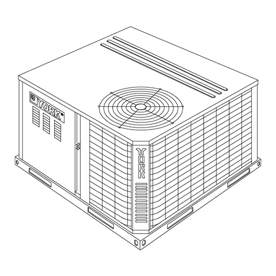
Affinity Model DNZ units are cooling/heating air
conditioners designed for outdoor installation. Only gas piping,
electric power and duct connections are required at the point of
installation.
The single or two stage gas-fired heaters have spark to pilot
ignition. The tubular heat exchangers are aluminized steel.
The refrigerant system is fully charged with R-410A Refrigerant,
and is tested and factory sealed.
TABLE OF CONTENTS
Phasing . . . . . . . . . . . . . . . . . . . . . . . . . . . . . . . . . . . . . . . 15
Gas Heat . . . . . . . . . . . . . . . . . . . . . . . . . . . . . . . . . . . . . . 15
Flue Vent Hood . . . . . . . . . . . . . . . . . . . . . . . . . . . . . . . . . 16
Airflow Performance . . . . . . . . . . . . . . . . . . . . . . . . . . . . . . . 19
Operation . . . . . . . . . . . . . . . . . . . . . . . . . . . . . . . . . . . . . . . 21
Heating Sequence Of Operation . . . . . . . . . . . . . . . . . . . . 21
Cooling Sequence Of Operations . . . . . . . . . . . . . . . . . . . 23
Start-Up . . . . . . . . . . . . . . . . . . . . . . . . . . . . . . . . . . . . . . . . . 23
Adjustment of Temperature Rise . . . . . . . . . . . . . . . . . . . 26
Checking Gas Heat Input . . . . . . . . . . . . . . . . . . . . . . . . . . . 26
Natural Gas . . . . . . . . . . . . . . . . . . . . . . . . . . . . . . . . . . . . 26
Typical Wiring Diagrams . . . . . . . . . . . . . . . . . . . . . . . . . . . . 27
LIST OF TABLES
11 Natural Gas Application Data-Single Stage . . . . . . . . . . 17
12 Natural Gas Application Data-Two Stage . . . . . . . . . . . . 17
13 Propane (LP) Gas Application Data-Single Stage . . . . . 18
14 Propane (LP) Gas Application Data-Two Stage . . . . . . . 18
15 Side Duct Application . . . . . . . . . . . . . . . . . . . . . . . . . . . 19
16 Bottom Duct Application . . . . . . . . . . . . . . . . . . . . . . . . . 19
17 Additional Static Resistance . . . . . . . . . . . . . . . . . . . . . . 20
18 Indoor Blower Specifications . . . . . . . . . . . . . . . . . . . . . . 21
19 Ignition Control Board FLASH CODES . . . . . . . . . . . . . . 23
20 Gas Rate Cubic Feet Per Hour . . . . . . . . . . . . . . . . . . . . 26
LIST OF FIGURES
10 Typical Field Power Wiring Diagram . . . . . . . . . . . . . . . 12
11 External Supply Connection External Shut-Off . . . . . . . 16
12 Flue Vent Outlet Air Hood . . . . . . . . . . . . . . . . . . . . . . . 17
13 Single Stage Gas Valve Front . . . . . . . . . . . . . . . . . . . . 24
14 Two Stage Gas Valve Front . . . . . . . . . . . . . . . . . . . . . . 24
15 Single Stage Gas Valve Rear . . . . . . . . . . . . . . . . . . . . 24
16 Two Stage Gas Valve Rear . . . . . . . . . . . . . . . . . . . . . . 25
17 Proper Flame Adjustment . . . . . . . . . . . . . . . . . . . . . . . 25
18 R-410A Quick Reference Guide . . . . . . . . . . . . . . . . . . 33
Safety Considerations
This is a safety alert symbol
labels or in manuals, be alert to the potential for personal injury.
Understand and pay particular attention to the signal words
DANGER, WARNING or CAUTION.
DANGER indicates an imminently hazardous situation, which,
if not avoided, will result in death or serious injury.
WARNING indicates a potentially hazardous situation, which,
if not avoided, could result in death or serious injury.
CAUTION indicates a potentially hazardous situation, which, if
not avoided may result in minor or moderate injury. It is also
used to alert against unsafe practices and hazards involving
only property damage.
Certified Quality
Management System
. When you see this symbol on
508258-YIM-C-0211
SO 9001
Advertisement
Table of Contents

Related Manuals for Johnson Controls AFFINITY DNZ024


Summary of Contents for Johnson Controls AFFINITY DNZ024
-
Page 1: Table Of Contents
R-410A AFFINITY™ SERIES DNZ024-060 SO 9001 2-5 Ton Certified Quality Management System TABLE OF CONTENTS General ......... . 1 Phasing . -
Page 2: What To Do If You Smell Gas
For use as a cooling only unit, cooling unit with Installation and service must be performed by a qualified supplemental electric heat or a forced air furnace. installer, service agency or the gas supplier. For outdoor installation only. Johnson Controls Unitary Products... -
Page 3: Installation
Latest Edition Page 17 of these instructions. Local building codes, and This equipment is not to be used for temporary heating of Local gas utility requirements buildings or structures under construction. Johnson Controls Unitary Products... -
Page 4: Unit Limitations
Table 1: Unit Limitations Unit Limitations Size Unit Voltage Applied Voltage Outdoor DB Temp (Tons) Max (°F) 208/230-1-60 (2.0) 208/230-1-60 208/230-3-60 (2.5) 460-3-60 208/230-1-60 208/230-3-60 (3.0) 460-3-60 208/230-1-60 208/230-3-60 (3.5) 460-3-60 208/230-1-60 208/230-3-60 (4.0) 460-3-60 208/230-1-60 208/230-3-60 (5.0) 460-3-60 Johnson Controls Unitary Products... -
Page 5: Location
The condenser coils should be protected from rigging 7.3, or 7.4 of Gas Installation Codes, CSA-B149.1 (in Canada) - cable damage with plywood or other suitable material. Latest Edition, and/or applicable provisions of the local building Johnson Controls Unitary Products... -
Page 6: Weights And Dimensions
Center of Gravity 4 Point Load Location (lbs.) Size (Tons) Shipping Operating 23.8 (2.0) (2.5) (3.0) 22.7 21.3 (3.5) 22.7 21.3 (4.0) (5.0) Table 3: Unit Accessory Weights Weight (lbs.) Unit Accessory Model Shipping Operating Add Economizer Johnson Controls Unitary Products... -
Page 7: Unit Dimensions Front
3. Units must be installed outdoors. Over hanging structure or shrubs should not obscure condenser air discharge outlet. 4. Units may be installed on combustable floors made from wood or class A, B or C roof covering materials. Johnson Controls Unitary Products... -
Page 8: Dimensions Front And Bottom
SIDE SUPPLY 14-1/2 AIR OPENING *CONDENSER 28-3/8 COIL 14-1/2 BACK BOTTOM SUPPLY AIR OPENING 3-3/8 SIDE RETURN AIR OPENING 14-1/2 4-1/4 1-3/4 1-3/4 BOTTOM RETURN 28-9/16 3-1/2 AIR OPENING 1-3/4 Figure 5: Dimensions Back and Bottom Johnson Controls Unitary Products... -
Page 9: Ductwork
Filters should be checked monthly; this is especially important NOTE: Be sure to note supply and return openings. since this unit is used for both heating and cooling. 1. 8” Roof Curb also available. Johnson Controls Unitary Products... -
Page 10: Condensate Drain
Refer to Figures 7 thru 10 for typical field wiring and to the appropriate unit wiring diagram for control circuit and power wiring information. Johnson Controls Unitary Products... -
Page 11: Typical Field Control Wiring Diagram Single Stage Thermostat-Single Stage Gas Heat
** = Minimum wire size of 18 AWG wire should be used for all field installed 24 volt wire. 24 VOLT TRANSFORMER PROGRAMMABLE THERMOSTAT ONLY Figure 8: Typical Field Control Wiring Diagram Single Stage Thermostat-Two Stage Gas Heat Johnson Controls Unitary Products... -
Page 12: Electrical Data
14.4 208/230-1-60 26.2 42.7 208/230-3-60 17.9 32.3 (5.0) 460-3-60 17.1 1. Minimum Circuit Ampacity. 2. Maximum Over Current Protection per standard UL 1995. 3. Fuse or HACR circuit breaker size installed at factory or field installed. Johnson Controls Unitary Products... -
Page 13: Single Stage Physical Data
1 - 20 x 20 x 1 1 - 20 x 20 x 1 1 - 20 x 20 x 1 2 - 20 x 12 x 1 2 - 20 x 12 x 1 2 - 20 x 12 x 1 Johnson Controls Unitary Products... -
Page 14: Two Stage Physical Data
1 - 20 x 20 x 1 1 - 20 x 20 x 1 1 - 20 x 20 x 1 2 - 20 x 12 x 1 2 - 20 x 12 x 1 2 - 20 x 12 x 1 Johnson Controls Unitary Products... -
Page 15: Compressors
Units are shipped with compressor mountings which are Use wrought iron or steel pipe for all gas lines. Pipe dope factory-adjusted and ready for operation. should be applied sparingly to male threads only. Do not loosen compressor mounting bolts. Johnson Controls Unitary Products... -
Page 16: Natural Gas Pipe Sizing Chart
1. Maximum capacity of pipe in thousands of BTU per hour must be fastened to the outside of the side gas control/ (based upon a pressure drop of 0.5 inch water column). electrical compartment with the screws provided in the bag Johnson Controls Unitary Products... -
Page 17: Natural Gas Application Data-Single Stage
4% for each 1,000 feet above sea level. 2. Based on 1075 BTU/Ft. 3. The air flow must be adequate to obtain a temperature rise within the range shown. Continuous return air temperature should not be below 55°F. Johnson Controls Unitary Products... -
Page 18: Propane (Lp) Gas Application Data-Single Stage
4% for each 1,000 feet above sea level. 3. Based on 2500 BTU/Ft. 4. The air flow must be adequate to obtain a temperature rise within the range shown. Continuous return air temperature should not be below 55°F. Johnson Controls Unitary Products... -
Page 19: Airflow Performance
1689 1118 1306 1142 Low (1) 1556 Low/Medium (2) 1648 1522 Medium (3) 1767 1664 1546 1015 (5.0) Medium/High (4) 1913 1819 1702 1049 1550 1102 High (5) 2103 1007 1990 1047 1855 1086 1674 1122 Johnson Controls Unitary Products... -
Page 20: Additional Static Resistance
1. The pressure drop through the economizer is greater for 100% outdoor air than for 100% return air. If the resistance of the return air duct is less than 0.25 IWG, the unit will deliver less CFM during full economizer operation. Johnson Controls Unitary Products... -
Page 21: Operation
“5” on the LED. If flame has been lost less than 16 times, the control attempts re-ignition after a 300 The control board energizes the pilot gas valve and spark second inter-purge period. outputs for an 85 second Ignition trial. The control de-energizes Johnson Controls Unitary Products... -
Page 22: Rollout Switch
Limit Switch (LS) - This control is located inside the heat switch closes, the control will restart the ignition sequence exchanger compartment and is set to open at the beginning with pre-purge. temperature indicated in the Temperature Controls Table Johnson Controls Unitary Products... -
Page 23: Cooling Sequence Of Operations
DO NOT try to light the burners by hand. This appliance is equipped with an ignition device which automatically lights The control circuit includes the following safety controls: the burners. High Pressure Switch (HP)- This switch protects against excessive discharge pressures due to a blocked Johnson Controls Unitary Products... -
Page 24: Single Stage Gas Valve Front
Small adjustments to the gas flow may be made by turning the Manifold Pressure Adjustment pressure regulator adjusting screw on the automatic gas valve. (Under Cap) Refer to Figures 13 and 14. Line Pressure Tap (1/8” NPT) 1/2” NPT (Inlet) Figure 15: Single Stage Gas Valve Rear Johnson Controls Unitary Products... -
Page 25: Two Stage Gas Valve Rear
Remove the two (2) #8 screws holding the pilot assembly Remove the burner assembly from the manifold assembly in place. by moving the burner assembly forward, turn at an angle Remove the pilot assembly. and pull back. Burners are now accessible for service. Johnson Controls Unitary Products... -
Page 26: Adjustment Of Temperature Rise
100,000 BTUH rating of the furnace. If the actual input is not within 5% of the furnace rating with allowance being made for the permissible range of the regulator setting, replace the orifice spuds with spuds of the proper size. Johnson Controls Unitary Products... -
Page 27: Typical Wiring Diagrams
508258-YIM-C-0211 Typical Wiring Diagrams Typical DNZ024-060 Cooling Unit with Single Stage Gas Heat 208/230-1-60 volt Wiring Diagram Johnson Controls Unitary Products... - Page 28 508258-YIM-C-0211 Typical DNZ024-060 Cooling Unit with Two Stage Gas Heat 208/230-1-60 volt Wiring Diagram Johnson Controls Unitary Products...
- Page 29 508258-YIM-C-0211 Typical DNZ030-060 Cooling Unit with Single Stage Gas Heat 208/230-3-60 volt Wiring Diagram Johnson Controls Unitary Products...
- Page 30 508258-YIM-C-0211 Typical DNZ030-060 Cooling Unit with Two Stage Gas Heat 208/230-3-60 volt Wiring Diagram Johnson Controls Unitary Products...
- Page 31 508258-YIM-C-0211 Typical DNZ030-060 Cooling Unit with Single Stage Gas Heat 460-3-60 volt Wiring Diagram Johnson Controls Unitary Products...
- Page 32 508258-YIM-C-0211 Typical DNZ030-060 Cooling Unit with Two Stage Gas Heat 460-3-60 volt Wiring Diagram Johnson Controls Unitary Products...
-
Page 33: 410A Quick Reference Guide
Figure 18: R-410A Quick Reference Guide Subject to change without notice. Printed in U.S.A. 508258-YIM-C-0211 Copyright © 2011 by Johnson Controls, Inc. All rights reserved. Supersedes: 508258-YIM-B-0610 Johnson Controls Unitary Products 5005 York Drive Norman, OK 73069...
Need help?
Do you have a question about the AFFINITY DNZ024 and is the answer not in the manual?
Questions and answers