Table of Contents
Advertisement
Quick Links
Advertisement
Table of Contents

Subscribe to Our Youtube Channel
Related Manuals for PreOmics APP96


Summary of Contents for PreOmics APP96
-
Page 2: Document Information
Company PreOmics GmbH Document Change Control Adaptations and updates of the present document are a consequence of technical improvements and amendments of the APP96. Any changes within this document are to be controlled. Document revisions Revision Document Name Reason For Change... -
Page 3: Table Of Contents
1.9.8 Heat Hazard ..........................12 1.10 Maintenance Safety ........................13 1.11 Type Plates and Symbols on the APP96 ................ 14 Installation ................................16 Parts of Delivery .......................... 16 General Technical Data ......................17 Environmental Conditions ...................... 18 LEDs ..............................18 Footprint (Instrument Dimensions with Standard Legs) ........ - Page 4 How to Create a Configuration Backup for Troubleshooting ......93 4.1.2 Copy a Backup File to a USB Stick ................93 4.1.3 Error Handling of Specific Components of APP96 ..........94 4.1.4 Dilutor ............................95 4.1.5 Tray Cooler ..........................96 4.1.6...
-
Page 5: Introduction
1 Introduction Thank you for choosing the APP96. We are confident it will become an integral part of your laboratory. Before using the APP96, carefully read this user manual and pay close attention to the safety information. Adhering to the instructions and safety guidelines provided is essential for the safe operation and maintenance of the instrument. -
Page 6: Policy Statement
The system is intended for use by professional users, such as technicians and physicians trained in molecular biological techniques and the operation of the APP96. The APP96 system is not intended for diagnostic use. The APP96 should be used exclusively with PreOmics kits specified for use with the APP96 and only for the applications described in the kit protocols. -
Page 7: Safety Information
Safety Information Before using the APP96, it is essential to read this user manual carefully and pay close attention to the safety information. Following the instructions and safety guidelines in the manual is crucial for the safe operation and maintenance of the instrument. NOTE: Translations of the Safety Information in other languages are available in the Safety Handbook delivered with the instrument. - Page 8 Avoid spilling water or chemicals onto the APP96. Damage caused by water or chemical spillage will void the user warranty. In case of an emergency, turn OFF the APP96 using the power switches on the power supplies and unplug the power cords from the power outlet.
-
Page 9: Electrical Safety
WARNING Risk of electric shock [W7] Do not open any panels on the APP96. Risk of personal injury and material damage may occur. Only perform maintenance that is specifically described in this user manual. To ensure satisfactory and safe operation of the APP96, follow these guidelines: The line power cord must be connected to a line power outlet that has a protective conductor •... -
Page 10: Environment
1.9.1 Operating Conditions WARNING Explosive atmosphere [W8] The APP96 is not designed for use in an explosive atmosphere. CAUTION Damage to the instrument [C4] Direct sunlight may bleach parts of the instrument and damage plastic parts. The APP96 must be located out of direct sunlight. -
Page 11: Chemicals
(SDSs) or OSHA or ACGIH documents. † WARNING Toxic fumes [W12] Do not use bleach to clean or disinfect the APP96 or used APP96 labware. Bleach in contact with salts from the buffers can produce toxic fumes. 11/102 M-000045 – Version 1... -
Page 12: Waste Disposal
Do not reach into the working area (inside the protective bar/enclosure) once a run has started. When loading the APP96 deck with reagents, plates, and samples, always stand clear of the instrument. Do not lean against the protective bar/enclosure while the robotic arm is in motion. -
Page 13: Maintenance Safety
CAUTION Damage to the instrument [C7] Do not use spray bottles containing alcohol or disinfectant to clean surfaces of the APP96. Spray bottles should only be used to clean items that have been removed from the worktables. CAUTION Damage to the instrument [C8] Do not use bleach, solvents, or reagents containing acids, alkalis, or abrasives to clean APP96. -
Page 14: Type Plates And Symbols On The App96
1.11 Type Plates and Symbols on the APP96 Type plate on the back of the instrument: Manufacturer ETL Listed Declaration ETL Listed Mark Waste Electrical and Electronic Equipment (WEEE) marking for Europe RoHS 2 Mark China 6) Registry number South Korea Compliance to applicable Standards in the UK 8) Compliance to applicable CSA and ANSI/UL Standards for use in Canada and the U.S. - Page 15 Type plate at the right side of the instrument: PAL system logo Instrument type Serial number 1D Barcode for serial number 2D Barcode for serial number 6) Year of manufacturing CTC Analytics logo 8) Country of manufacture Next to the Thermal Mixer: Biohazard –...
-
Page 16: Installation
2 Installation Parts of Delivery PAL RTC system for PreOmics iST/iST-BCT workflow, consisting of: 1 pc PALbase 850 X/Y unit with APP96 Control Board SII 1 pc PAL RTC z-head with Smart Reader 1 pc Park Station 1 pc PALterminal incl. holder... -
Page 17: General Technical Data
Pollution degree (c) Moisture protection (d) Normal (IPXO) Voltage 36 V DC Fuse (PAL Control Board) T6.3 A/250 V APP96 Power Supply Input line voltage Grounded AC, 100 to 240 V Input line frequency 50–60 Hz Input power Output voltage... -
Page 18: Environmental Conditions
Steady on Application "ready" Blue Blinking Updating software Yellow Blinking Application software initialized (start loading software) Blinking APP96 System booting fast Steady on Software failed to start application Application software is not installed Fatal error 18/102 M-000045 – Version 1... - Page 19 Yellow Steady on Activity execution error Fatal error Blinking Configuration error LED at the rear side of the instrument During the APP96 System boot up, the following status changes can be observed LED Color LED PAL System status status Green Steady on PAL System "ready"...
-
Page 20: Footprint (Instrument Dimensions With Standard Legs)
900 mm (35.4 in). There should be enough additional space to the left to accommodate two 1-liter glass bottles. 2.6 Installation Order Install the APP96 in the following order: Unpacking & Assembly Part 1 Calibration & Teaching part 1 Apply configuration via Cloner software... -
Page 21: Assembly Of App96 Part I
2.7 Assembly of APP96 Part I Start with setting up the left and right foot at the beginning, loosen screws and connectors of the feet. Install the main axis, put it on top of the feet, and fix it with screws. - Page 22 Install the left foot. Do not install the Park Station (=toolholder) at the very edge; leave a gap of 2–3 cm to the left end of the main axis and install as usual with screws. Move the left foot close to the Park Station afterward by loosening the screws and fixing them again after moving it closely to the Park Station.
- Page 23 Remove the caps of the washing ports and connectors. Connect the wash tubing as shown in the photo and connect the waste tubing. 23/102 M-000045 – Version 1...
- Page 24 Install the wash port as usual using the screws directly to the right of the left foot. Install the Tray Holder frame using the screws to the right of the Fast Wash station. Leave 2–3 cm space between the Tray Holder and Fast Wash station. 24/102 M-000045 –...
- Page 25 Install the Tray Cooler to the right of the middle foot (this is an optional item, not part of standard delivery). If the middle foot is not present, leave 5 cm space for the Tray Holder. Install only the housing; the Peltier cooler will follow later.
- Page 26 Ground plate of the Thermal Mixer. Attach the ground plate to the bottom side of the mixer. Do NOT install the deep-well plate adapter beforehand! 26/102 M-000045 – Version 1...
- Page 27 Installation of the ground plate on the mixer using four screws. Install the mixer with the ground plate on the joints of the right foot. 27/102 M-000045 – Version 1...
- Page 28 Install the 2-port Dilutor to the far left, next to the Park Station (on the left side), using screws as usual. Fix with screws using the 2 backmost screw holes. 28/102 M-000045 – Version 1...
- Page 29 Install the syringe holder (=Dilutor) below the Dilutor tubing holder using two screws. Install the safety bar holder to the far right with two screws. 29/102 M-000045 – Version 1...
- Page 30 Keep the distance screw and holder in a safe place. Attach the APP96 head to the bolts on the y-axis and fix it with the attached screw. Move the Robotic Arm over the Tray Holder or Park Station so that the Z-arm cannot fully slide down.
- Page 31 Mount the head cover onto the Z-arm straight from the top without touching electronic boards and cables! Make sure the Dilutor tubing stays left of the Z-Head. Fix the APP96 head cover at the back side using the provided screw. 31/102...
- Page 32 Install the Terminal holder to the far right (standard) with two screws. It can also be applied on the left side (frontmost screw holes), e.g., due to space requirements. Carefully insert the Peltier cooler into the Tray Cooler frame (pay attention to the sockets on the rear side!) 32/102 M-000045 –...
- Page 33 Connect the wire from the Dilutor tubing with the Dilutor tool by loosening the small screw at the left. Insert the wire, hold it in place, and fix it again with the screw (circle). Insert the needle, including the screwring, into the Dilutor tool, starting from the top (arrow). Fix the needle with the screwring.
- Page 34 Fix the Dilutor tubing in the groove and screw the connector on top of the needle tight. Make sure there are no kinks in the tubing! Put the assembled Dilutor tool in the Park Station, Slot 1. 34/102 M-000045 – Version 1...
-
Page 35: Calibration & Teaching
Some modules have 2 bus ports; these can be used for daisy chaining the connections between the modules. Connect the cable from one power supply to the APP96 power socket at the rear side of the instrument. Connect the second power supply to the power socket of the Tray Cooler. -
Page 36: Set Regional Settings
The Installation wizard begins with basic setup items like "Regional Settings", "Set Date and Time", etc. Some of the list items covered can be accessed under the menu item "Setup". As mentioned above, the "Installation" wizard is typically used during the installation process. The menu item "Setup" will be used during routine operation. - Page 37 Item Description Currently, English (United States) is the only language that is Language available. Regional Settings Region: This item corresponds to the country settings of the computer operating system. The country setting mainly influences formatting, such as dates and numbers. Items displayed in green are only visible in the "Extended User Level".
-
Page 38: Set Date And Time
2.8.2 Set Date and Time Select the wizard item Set Date and Time to adjust the date and time. 38/102 M-000045 – Version 1... -
Page 39: Set Palrobot Name
Item Description Date Date format yyyy/mm/dd Time format hh:mm:ss Time Time Zone Greenwich Mean Time (GMT) plus or minus the time deviation (in hours) from GMT. Items displayed in green are only visible in the "Extended User Level". 2.8.3 Set PALrobot Name Select the wizard item Set PALrobot Name to assign a name to the system for identification 39/102 M-000045 –... -
Page 40: Setup Network (Can Be Skipped If Just The Terminal Is Being Used)
2.8.4 Setup network (can be skipped if just the Terminal is being used) Select the wizard item Setup Network to enable network communication from the APP96 System to the computer TCP/IP. 1. Select either the mode "DHCP" or enter a unique fixed IP address. See details below. - Page 41 The example shown in the figure above is valid for the situation with a connected network cable. The default addresses are correctly shown for the "peer-to-peer setup as explained below. Please note that the default gateway address is not used, see explanation below. When the network cable is not connected, and a LAN communication is not established, the previously entered network settings are maintained.
- Page 42 3. When the settings have to be changed, select one network parameter after the other and enter the required numbers. The examples below show the default values. Item Description Setup Network Defines the network communication parameters. DHCP Dynamic Host Configuration Protocol. If activated, an IP address is dynamically sought throughout the provided network.
-
Page 43: Set Homing Strategy
2.8.5 Set Homing Strategy The homing strategy determines in which order the three axes of the APP96 Head are being homed. The homing strategy can also be selected as a menu item for "RobotArmLeft" under "Drives (PALdrives)". Three different homing strategies can be selected: Default •... -
Page 44: Calibrate Paldrives
Homing Strategy Default (Recommended) The default order for homing the 3 axes of the APP96 Head is z – y – x, meaning the z-axis (up and down) of the APP96 Head is homed first, followed by the y-axis (back and forth), while the x-axis (right and left) is homed at last. - Page 45 and stored as the electronic stop point. This calibration of the axes is mandatory and ensures reliable performance. This step must be repeated if a PAL Drive has failed, been replaced, or if any other major error has occurred. This calibration task ensures that the PAL Robot returns to reliable operation. For the calibration procedure, a tool with a plunger coupling is mandatory.
- Page 46 4. Press "Next" to continue with "Calibrate Plunger Sensor" (step 3), and when finished, press "Next" again to "Calibrate Coupling". 5. Steps 5 and 6 calibrate the coupling of a PAL Tool. The wizard text explains that the PAL Head has to be moved above the "Coupling Pivots"...
-
Page 47: Teach Pal Tool Station (Only Pal Rtc)
6. In step 6, the sensor of the plunger drive is calibrated. When finished, press "Next" to continue to step 7. 7. Step 7 completes the "Calibration Wizard" for the PAL RTC. The PAL Head moves back to the "Home" position. - Page 48 1. Select the wizard item Teach PAL Tool Station. The wizard automatically turns off the power to the PAL Robot to enable a manual movement of the PAL Head to the first slot. If the previous step was performed, Calibration PALdrives, a PAL Tool should still be installed. If, for any reason, there is no installed PAL Tool, the PAL Robot will recognize the situation and will go through an intermediate step to mount a tool.
-
Page 49: Set Reference Point
3. Repeat the previous steps to teach the positions for Slots 2 and 3. The last step moves the PAL Head back to the "Home" position. 2.8.8 Set Reference Point The reference point can, in theory, be any point within the system's working range. However, for practical reasons, it is advisable to select a fixed Teaching, such as the Tray Holder, barcode reader, or Fast Wash Module. - Page 50 Manually position the PAL Head exactly within the guiding rings of the lunette. Store this value. It is advisable to hold the y-axis with one hand and, with the other hand, move the tool body in a controlled manner to the PAL Head Teaching position. Do NOT hold the needle guide to move the PAL Head. This part is mechanically flexible, and holding it could lead to misalignment.
-
Page 51: Calibrate Pal Tools
If for any reason, the referencing (Set Reference Point) has been repeated, it is mandatory to recalibrate all PAL Tools. Using the step "Set Reference Point" clears any previous calibration data stored for the individual tools. Beginning with PAL3 Firmware version 1.4.0 a message will appear to inform the operator of the necessary steps. - Page 52 3. After the first step of PAL Tool calibration, the wizard will park the installed PAL Tool and pick up the next tool, starting with the tool in Slot 1 and consecutively in Slots 2 and 3. 52/102 M-000045 – Version 1...
- Page 53 53/102 M-000045 – Version 1...
-
Page 54: Setup Pal Modules
2.8.10 Setup PAL Modules This section describes how to predefine the parameters of the various PAL Modules. This setup is usually performed once during the initial installation of the PAL System. 2.8.11 Teach PAL Modules The term "Teaching" is used for the definition of the x-, y-, and z-axis positions for each PAL Module. Please note the difference between "active"... - Page 55 Active PAL Modules Passive PAL Modules In cases where vial types are specified, the following teaching points are outlined. 55/102 M-000045 – Version 1...
-
Page 56: Options Pull-Up Menu
2.8.12 Options Pull-up Menu Opening the pull-up menu "Options" will provide the list of items specific to each PAL Module. Item Description Check the teaching positions of the selected PAL Module. Check Teach Allows the user to teach the X-, Y-, and Z-Positions of the selected PAL Module. -
Page 57: Create Configuration Backup File
4. Press "Next" to continue within the wizard; the PAL Head moves to the next PAL Module. The figure above is the only example shown for this wizard; all other modules are treated in the same manner as described above. The pull-up menu "Previous"... - Page 58 2. After defining the file name, press "Start" to begin the process. The blue blinking light indicates that the process has been executed. The progress of the backup is visible on the screen, to inform the operator of the percentage of the backup completed. 3.
- Page 59 The backup file is stored on the PAL SD card, which is installed on the PAL control board. This file can be saved on the PAL3 USB Stick. The file can also be used to "Restore" the PAL3 Firmware. Please note that the "Restore" option is only available in the Extended User Level.
-
Page 60: Overview Of Pal Teaching Points
2.8.15 Overview of PAL Teaching Points Park Station Fast Wash Tray Holder Tray Cooler Thermal Mixer Teach the above-shown positions before continuing with the Configuration Cloner software. 60/102 M-000045 – Version 1... -
Page 61: Configuration Cloner
If the Configuration Cloner software and/or PAL backup are not available, the user should contact PreOmics. Refer to Chapter 2.10 for the correct naming of each module. NOTE: The user cannot connect to the destination instrument when there are pending service messages, and the instrument is not displaying a green LED. - Page 62 Start the Configuration Cloner software: Select the Offline Configuration Click on File → Open and select the source file “PAL.pcb”. The configuration of the source file is shown in the window below the configuration file. Connect to the Destination PAL Robot by entering the corresponding IP Address and clicking the “connect”...
-
Page 63: Instrument Configuration: Naming And Tray Definitions
2.10 Instrument Configuration: Naming and Tray Definitions It is important that each module has the correct name and object definitions. After using the Configuration Cloner, please verify the naming conventions and object types of the various modules to ensure accuracy. 1: Dilutor 2: Park Station 3: Fast Wash... -
Page 64: Assembly Of Pal Part 2
2.11 Assembly of PAL Part 2 Back side of the SPE washing station – lower part, with connector to waste tubing. Connect the waste tubing to the SPE washing station on Tray Holder, Slot 3. Put waste tubings from Fast Wash and SPE Wash station into the waste bottle. Add the grey SPE cartridge adapter on top of the white bottom part. - Page 65 Rack setup of the Tray Cooler: Slot 1: black plate (cover for unused position). Slot 2: 10 mL alloy adapter plate, VT15 rack. Add the colored label (from the Installation kit) between the top and middle rows. Slot 3: small alloy adapter plate, lower part of SPE washing station (without tubing connector). Add the deep-well plate adapter to the Thermal Mixer.
- Page 66 Insert or change the Syringe in the Dilutor 1 using the Terminal: Activate extended user mode. Select Dilutor 1. Options → Change Syringe. Move (wait until Plunger has moved to the bottom position!). Remove the long screw to install the (new) syringe. Attach the syringe and put the long screw back, attaching it to the plunger.
- Page 67 Safety bar installation on the right side. Fix with one screw on each side, then lift the safety bar up and fix with the second screw on each side. 67/102 M-000045 – Version 1...
-
Page 68: Teaching Of Poptips, 96-Well Plates, And Vial Positions
2.12 Teaching of POPtips, 96-Well Plates, and Vial Positions After finishing the second part of the assembly, all positions having racks or plates must be calibrated (3-Point calibration). Before teaching a position, ensure the naming of the position is correct: Tray Holder 1/Slot 1: Elute_RT Cap Type: NoCap ... - Page 69 Start with Slot 1 and place the COLLECTION PLATE there. Check that the Tray Holder fixes the plate securely. If the plate can move, ensure the metal springs are correctly inserted and provide enough tension. Place the BLACK POPtip holder on top of the COLLECTION PLATE, as illustrated in the image above. Insert a POPtip from the installation kit into positions 1 (A1), 85 (H1), and 96 (H12).
- Page 70 Teach Slots 2 and 3 of the Tray Cooler as described for the Tray Holder. Prepare the Thermal Mixer: Add the SAMPLE PLATE (96-deep-well plate from the Installation kit) and make sure it is flat on the Adapter. Perform the teaching as described in Positions 1 (A1), 85 (H1), and 96 (H12), but without POPtips. Teaching the Waste: Select the Waste on the Terminal and click on Teach PAL Module.
-
Page 71: Uploading Of Scripts
Included with the instrument is a USB stick containing the scripts necessary for verification of the teaching process and the scripts for the customer workflows. Upload all these scripts to the APP96 to verify the teaching and prepare the instrument for customer use. For instructions on how to upload the scripts, refer to Chapter 3.4.4. -
Page 72: Dispense Test
Place this empty vial, also without the screw cap, at position 3 on Tray Holder, Slot 2. During the Dispense test, the APP96 will pick up 100 µL from the Source vial five times and transfer it to the Destination vial. This should result in 0.5 mL (equivalent to 0.4985 g at 25°C/77°F) in the Destination vial. -
Page 73: Acceptance Criteria
2.16 Acceptance Criteria Refer to the following table for the criteria required for a successful installation. Record the results in the Acceptance Report document. Acceptance test Tasks Thermal Mixer heating to 37°C/80°C (sensor Check sensor temperatures after setting the target readout) temperature. -
Page 74: User Guide
The APP96 enables users to fully automate the processing of up to 96 samples in a single run. It is designed to automate selected PreOmics kits. The APP96 controls integrated components, including a heated shaker, pipetting system, and robotic gripper. -
Page 75: App96 Overview
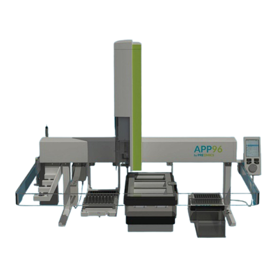
24 samples 48 samples 96 samples 3 hours 3.7 hours 5.2 hours 8.2 hours 3.1.2 APP96 Overview 1: Dilutor 2: Park Station 3: Fast Wash 4: Tray Holder 5: Robotic Arm with Dilutor Tool 6: Tray Cooler 7: Thermal Mixer... -
Page 76: App96 Deck Layout
Tray 6: Elution position – used for elution of peptides at 10°C. The Thermal Mixer has only one position for a 96-deep-well plate: Tray 7: SAMPLE PLATE – use only SAMPLE PLATE from PreOmics kits designed for use with the APP96 (0.5 mL deep-well plate). -
Page 77: Optic And Acoustic Signals
3.2 Optic and Acoustic Signals There are two LEDs on the instrument showing the status during the booting process as well as during operation. One is located at the front of the housing on the right edge, and the other is located at the rear side of the housing on the left edge. -
Page 78: Preparing App96 For A Run
3.3 Preparing APP96 for a Run Power ON the APP96 by switching both external power supplies and wait until the self-test is complete, indicated by the green LED steady on. Attach the bottle with the operating solution (89.9 % ddH O, 10% Acetonitrile, 0.1% Formic acid) at... - Page 79 SAMPLE PLATE Sample load direction Dissolve lyophilized DIGEST vial(s) with 3.125 mL RESUSPEND buffer. Place the LYSE (or Lyse-BCT) reagent vial(s) in the Tray Holder and all other reagents (DIGEST, STOP, WASH1, WASH2, ELUTE) in the Tray Cooler, as shown in the figure below. Each reagent vial is sufficient to prepare up to 48 samples. Place the SAMPLE PLATE on the Thermal Mixer and ensure that it is firmly attached.
- Page 80 Place the COLLECTION PLATE on one of the elution positions: for immediate drying of peptides after the run at room temperature (Tray Holder (RT); position 1) or in the Tray Cooler (position 6) for prolonged storage of peptides before drying. COLLECTION PLATE position at RT or 10°C Place the black POPtips Holder on top of the COLLECTION PLATE, ensuring it is aligned properly on top of the plate!
- Page 81 POPtips Holder loaded with POPtips 10. When the instrument setup is finished, continue with the Terminal. Navigate on the Terminal to “Local Script” by pressing the left button. Select “Methods” → Choose the desired method and click on “Edit”. Change the number of samples and the start position on the deep-well plate (=Index). Edit further parameters if necessary and click on “Save”.
- Page 82 12. Start a run by selecting either “Start” or “Start Job 1” (=the Job that was just created). NOTE: Choosing “Start from Job 1” will initiate all open Jobs consecutively, including Job 1. 13. Once the run starts, the system will automatically verify the presence of plates, vials, and POPtips. If any position is empty, the run will be aborted (indicating a Loadcheck failure), and the process must be restarted.
-
Page 83: Usage Of App96 With The Terminal
3.4 Usage of APP96 with the Terminal All operations of the APP96 instrument are started via the Terminal. It is therefore crucial to get familiar with the handling of the Terminal to start runs or send simple commands. In the following chapter, the structure of the Terminal and all steps needed to start a run will be explained. -
Page 84: Selecting An Item Or Command
3.4.2 Selecting an Item or Command The selected item within a menu is always highlighted in turquoise color. Users can navigate through the menu and select other items using the scroll wheel. If a menu is too long to be fully displayed, small arrows at the top and/or bottom indicate that only a portion of the menu is visible on the screen. -
Page 85: Options Menu
3.4.4 Import a New Script If a new script/workflow is offered by PreOmics, the script has to be uploaded on the instrument via the Terminal. Insert a USB stick (FAT32) with the script (as .xml file) inside the folder “Scripts” in the PAL USB-Port (back side of the xy-axis). -
Page 86: Starting A Run With The Terminal
3.4.5 Starting a Run with the Terminal The following steps outline how to start a run using the terminal. Initially, a method must be created to define the variable parameters of the underlying script. For a detailed description of these variable parameters, refer to Table 1. - Page 87 Table 1. Hardware & selectable parameters Make sure that the hardware components (fastWashStation, thermalMixer_1, and toolDilutor) are set (this must be done only the first time the method is used). Parameter Default Min–Max numberOfSamples 1–96 startIndex 1–96 sampleTransferVolume 200 µL 50–250 µL lysisTemperature 80°C...
- Page 88 4) Start a Job Go to “Local Scripts” → Job Queue → Enter Select Start or Start Job 1. Selecting Start From Job 1 will execute all Jobs, including Job 1. 5) Finish a Job Once the Job is complete, this will be shown on the Terminal. Click on “Finish”...
-
Page 89: Useful Workflows On The Terminal
3.5 Conversion Table for Numbering in Well Plate/Instrument Format The APP96 uses consecutive numbering from 1 to 96, with 1 located in the upper left corner and 96 in the lower right corner. Below is a conversion table that maps the instrument’s numbering to the typical 96-well plate numbering, ranging from A1 to H12. -
Page 90: User Maintenance
Routine cleaning and inspection help maintain the instrument’s reliability and performance. Over time, components can wear out or become contaminated, which may lead to errors in sample handling and analysis. Performing preventive maintenance on the APP96 annually will help extend its lifespan and ensure continued accuracy and precision. - Page 91 Insert a new needle along with the washer, making sure it passes through both black cavities. Screw the needle tight. Ensure the tubing has no kinks and is fixed in the groove on the module, as shown below. Place the tool back in the Park Station slot where it was removed. Use the Terminal →...
-
Page 92: Error Handling Guide
4 Error Handling Guide If the APP96 encounters an exception, an error message will appear on the Terminal. Such exceptions usually cause the run to be aborted to prevent potential damage to the system. For example, a typical error might be: Object not detected or detected too early: When approaching an object such as a reagent vial, 96- •... -
Page 93: How To Create A Configuration Backup For Troubleshooting
4.1.1 How to Create a Configuration Backup for Troubleshooting Follow the steps in the images below (from left to right) to create a diagnostic backup file. In the last step, provide a name for the backup file and click “Start”. The Terminal will notify when the backup is complete. 4.1.2 Copy a Backup File to a USB Stick Use a USB stick with at least 8GB of storage that is not NTFS formatted (e.g., FAT or FAT32). -
Page 94: Error Handling Of Specific Components Of App96
Copying only takes a few seconds. Afterward, remove the USB stick from the system and send the file to the local service provider. 4.1.3 Error Handling of Specific Components of APP96 The following section provides error-handling information specific to the different modules of the PAL. 94/102... -
Page 95: Dilutor
4.1.4 Dilutor Observation Recommended Action Syringe needle bending. Check the teaching position for the x, y, and z axes. Solvent flow not sufficient. Check the cleanliness of the solvent frits. Air bubbles in solvent lines. Check the solvent levels in the reservoir bottles. -
Page 96: Tray Cooler
Check for a "Pending Message" and, if necessary, take corrective actions. Power supply problem Is the APP96 power supply unit connected and turned ON? 4.1.6 Fast Wash Observation Recommended Action Syringe needle bending. -
Page 97: Contact
Periodically check the Service section on the Terminal for notifications regarding other potential issues with the instrument. 4.2 Contact In case there is a problem with the instrument, please contact: www.preomics.com Technical Support 97/102 M-000045 – Version 1... -
Page 98: Preventive Maintenance (Pm)
5 Preventive Maintenance (PM) Regular maintenance procedures are essential for maintaining the accuracy and precision of the APP96. The instrument should be serviced annually by a trained service engineer—do not attempt to service it yourself. A service contract can be obtained from the local Service Distributor (Bruker Daltonics). - Page 99 Clean and grease points on the x-axis. 99/102 M-000045 – Version 1...
- Page 100 Clean and grease points II. 100/102 M-000045 – Version 1...
- Page 101 Clean and grease points on the y-axis. 101/102 M-000045 – Version 1...
-
Page 102: Appendix A -Safety Information In Different Languages
6 Appendix A – Safety Information in Different Languages Visit www.preomics.com/support for safety information in other languages. Safety information is available in the following languages: 102/102 M-000045 – Version 1...
Need help?
Do you have a question about the APP96 and is the answer not in the manual?
Questions and answers