Table of Contents
Advertisement
Quick Links
Advertisement
Table of Contents

Related Manuals for Holybro Kakute F7 mini V3


Summary of Contents for Holybro Kakute F7 mini V3
- Page 1 #11046 Kakute F7 mini V3 User Manual & Installation Guide v1.0...
-
Page 2: Table Of Contents
Contents Overview ...................... 2 Specifications Pinout Diagram ..................3 Warranty and Return Policy Installation Guide ..................4 Updating Betaflight Firmware ............11 Installing Drivers Installing Betaflight Configurator Initial Configuration ................15 Flashing New Firmware Connect to The Board Ports OSD ......................19 Configuration Using The OSD .................. -
Page 3: Overview
Warranty and Return Policy If you believe that your Kakute F7 mini V3 is defective, please contact us. If we determine that the board is defective, it will be repaired or replaced at no charge to you. We may ask you to send your Kakute to our service center for examination or repair. -
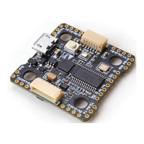
Page 4: Pinout Diagram
Pinout Diagram Function Top of board To camera OSD control 5v output (1.0A max) Video output to video transmitter Video input from FPV camera Ground SDA, SCL C connection (for peripherals) R1, T1 UART1 RX and TX R2, T2 UART2 RX and TX R3, T3 UART3 RX and TX R4, T4... -
Page 5: Installation Guide
When in doubt, it’s always better to leave a little extra wire. You will most likely be installing the Kakute F7 mini V3 with a Power Distribution Board (PDB) or a 4-in-1 ESC. The Kakute F7 mini V3 will probably install on top of this board, in the flight control stack. - Page 6 If you intend to use telemetry, solder the telemetry wire from your receiver to the T2 pad on the Kakute F7 mini V3. On FrSky receivers, the telemetry wire is labeled as SmartPort. If you are using Crossfire, there is no separate telemetry wire.
- Page 7 Unify Pro is one exception: it requires 5v maximum. Remember that the rated load of the 5v regulator on the Kakute F7 mini V3 is 1 amps. This means that the sum of the accessories you run from the regulator cannot exceed 1 amps. This should be enough current to run a camera, receiver, and video transmitter (even a high-powered vTX like the Unify Pro).
- Page 8 For Tramp Telemetry vTX including the ImmersionRC Tramp and the Holybro Atlatl V1, solder the T wire from the vTX to the T1 pad on the Kakute F7 mini V3. Other vTX may label this pin differently. Refer to their documentation.
- Page 9 If your ESCs support telemetry, and if you intend to use it, then solder each of the ESC telemetry wires to the R4 pad that is in the plug header. The Kakute F7 mini V3 comes with a plug that fits into this header.
- Page 10 4-in-1 ESC. Your PDB or 4-in-1 ESC may have another vBat pad that is specifically designed for powering an accessory like the Kakute F7 mini V3. It’s simpler to use a dedicated pad or wire, rather than soldering to the main Pin1→Pin8...
- Page 11 ‘C’ pad on the Kakute F7 mini V3. If your camera uses digital control, solder the camera TX wire to pad R3 on the Kakute F7 mini V3. Solder the camera RX wire to pad T3 on the Kakute F7 mini V3.
-
Page 12: Updating Betaflight Firmware
3. Download the ImpulseRC Driver Fixer from here. 4. Run the ImpulseRC Driver Fixer. It will instruct you to plug in your flight controller. 5. Plug the Kakute F7 mini V3 into your PC via USB. The ImpulseRC Driver Fixer should complete successfully. -
Page 13: Installing Betaflight Configurator
The video linked above shows a process of using Zadig to replace the VCP driver. The ImpluseRC Driver Fixer is an easier way of doing the same thing. So, use the ImpulseRC Driver Fixer and don’t mess around with Zadig like the video shows. Is It Over Yet? THAT WAS SUPER ANNOYING WASN’T IT. - Page 14 USB cable. Leave the button pressed for a moment after plugging in the USB cable to be sure it “takes”. If your Kakute F7 mini V3 is in bootloader mode, then you will see “DFU” in the pulldown menu in the upper-right of the configurator, as shown here: If you don’t see DFU in the pulldown menu, then either the board didn’t detect that you had the...
- Page 15 2. Select “KAKUTEF7MINIV3” in the “Choose a board” pulldown menu. If you flash any other board type, the Kakute F7 mini V3 will not function. It won’t be damaged, it just won’t work until you flash KAKUTEF7MINIV3 to the board.
-
Page 16: Initial Configuration
Initial Configuration The full configuration of Betaflight could take hours to document. In this section, we’ll describe a few things that are specific to this board. This won’t be enough to get you into the air, so we’ll also point you to some videos you can watch if you’re not perfectly sure what else you need to do. - Page 17 Setting B: Applicable for Analog VTx(SKU13008 Atlatl HV V2,SKU13012 Atlatl HV micro) The UARTs on your Kakute F7 mini V3 are versatile; any UART can be used for any function. This is different from the Kakute F4, in which certain functions had to be assigned to certain UARTs. In the wiring instructions above, certain UARTs were suggested, such as soldering the SBUS receiver to R6.
- Page 18 On each row in the Ports tab, enable the one function that you connected ot the TX and/or RX pads for that UART. The most common options are below. USB VCP is the port that is used to talk between the Kakute F7 mini V3 and the Configurator •...
- Page 19 Next, go to the Receiver section of the “Configuration” tab. Since the Kakute F7 mini V3 only supports serial-type receivers, configuration of this section is simple.
-
Page 20: Osd
In the OSD tab, you can choose which values you want to see on screen while you are flying. Enable and disable individual elements using the Elements toggles on the left. The Video Format section lets you choose whether your camera is NTSC or PAL. Betaflight defaults this value to Auto, but Auto sometimes picks wrong. - Page 21 80% of its rated capacity without sagging below 14.0 volts might need retirement. The current sensor in your Kakute F7 mini V3 has been set with a nominal calibration value. However, you may be able to improve the accuracy by performing a more precise calibration. We recommend that you record the mAh used at the end of your first few flights, then compare it to the mAh that your battery charger puts back into the batteries.
-
Page 22: Using The Osd
Using The OSD If you are using a Betaflight Flight Controller with Betaflight OSD, you can manage the Atlatl’s transmit power and channel from within the OSD. Mode 2 Mode 1 The graphics above show the stick command to bring up the OSD menu. The stick command is: throttle centered, yaw left, pitch forward. - Page 23 The screen to the right shows the current vTX settings. From here, you can change the frequency band, channel, and power level of the video transmitter. After making the changes, move the cursor to “Set” and press roll-right to confirm the settings. P a g e | 22 Kakute F7 mini...
-
Page 24: Saving Your Configuration
Saving Your Configuration Once you have finished building, configuring, and tuning your multirotor, it’s a good idea to back up your configuration so that you can restore it later. This is useful if you lose your quad, or if you damage your flight controller, or if you accidentally lock yourself out of your flight controller and must reset it to get back in. -
Page 25: Additional Reference
Additional Reference Here are some links to additional videos to help you build your quadcopter successfully. Betaflight 3.3 Ultimate Setup Guide https://www.youtube.com/watch?v=8vJCrHj9s6s How to Calibrate Your ESCs https://www.youtube.com/watch?v=o3Mg-9M0l24 If you are using an analog protocol like Oneshot or Multishot, calibrating your ESCs is mandatory. Most ESCs today support Dshot. -
Page 26: Adjust Pids / Rates / Vtx From Taranis
Adjust PIDs / Rates / vTX from Taranis If you have a FrSky Taranis radio and if you are using telemetry (such as SmartPort, FPort, or Crossfire), you can use your Taranis to change your PIDs and rates. This is done by installing a piece of programming code called a Lua script on your Taranis. If you are also using SmartAudio, you can use a Lua script to change your vTX settings.
Need help?
Do you have a question about the Kakute F7 mini V3 and is the answer not in the manual?
Questions and answers