Table of Contents
Advertisement
Quick Links
Advertisement
Table of Contents

Subscribe to Our Youtube Channel
Related Manuals for Quincy Compressor QHP-850


Summary of Contents for Quincy Compressor QHP-850
- Page 1 HEATED...
- Page 2 Instruction book 9829 2122 57...
- Page 3 Instruction book Quincy Compressor QHP-850, QHP-1050, QHP-1220, QHP-1500, QHP-1700, QHP- 2000, QHP-2600, QHP-3000, QHP-3400 Instruction book Original instructions Copyright Notice Any unauthorized use or copying of the contents or any part thereof is prohibited. This applies in particular to trademarks, model denominations, part numbers and drawings.
- Page 4 Instruction book quincycompressor.com 9829 2122 57...
-
Page 5: Table Of Contents
Instruction book Table of contents Table of contents ........................5 Safety precautions ......................8 Safety icons ........................8 Safety precautions, general ..................... 8 Safety precautions during installation ................8 Safety precautions during operation ................10 Safety precautions during maintenance or repair ............11 General description ..................... - Page 6 Instruction book Event history menu ....................... 45 3.10 Test menu ........................46 3.11 Service menu ........................ 48 3.12 Protections menu ......................52 3.13 Week timer menu ......................54 3.14 Info menu ........................64 3.15 Modifying settings ......................65 3.16 Web server ........................71 3.17 Programmable settings ....................
- Page 7 Instruction book Preventive maintenance schedule ................115 Service kits ........................116 Service agreements ....................116 Service plan......................... 117 Filling instructions ......................117 Precautions before storage ..................118 Optional equipment ....................120 Precautions for optional equipment ................120 Options ........................120 Problem solving ......................
-
Page 8: Safety Precautions
Instruction book Safety precautions Safety icons Explanation Danger for life Warning Important note Safety precautions, general General precautions 1. The dryers are designed for normal indoor use. 2. The operator must employ safe working practices and observe all related work safety requirements and regulations. -
Page 9: Precautions During Installation
2. The unit is designed for indoor use. If the unit is installed outdoors, special precautions must be taken; consult Quincy compressor. 3. Install the dryer as level as possible and fix it firmly to the floor. -
Page 10: Safety Precautions During Operation
Instruction book Also consult following safety precautions: Safety precautions during operation Safety precautions during maintenance. These precautions apply to machinery processing or consuming air or inert gas. Processing of any other gas requires additional safety precautions typical to the application which are not included herein. -
Page 11: Safety Precautions During Maintenance Or Repair
Instruction book Also consult following safety precautions: Safety precautions during installation Safety precautions during maintenance. These precautions apply to machinery processing or consuming air or inert gas. Processing of any other gas requires additional safety precautions typical to the application which are not included herein. -
Page 12: General Description
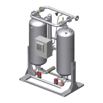
After maintenance or repair, a functional test with depressurized vessels must be performed to check the correct operation of the dryer. General description Introduction Front view Front view of QHP-850 9829 2122 57... - Page 13 Instruction book Front view of QHP-1050 9829 2122 57...
- Page 14 Instruction book Front view of QHP-1220 up to QHP-2000 9829 2122 57...
- Page 15 Instruction book Front view of QHP-2600 to QHP-3400 9829 2122 57...
-
Page 16: Rear View
Instruction book Rear view Rear view of QHP-850 9829 2122 57... - Page 17 Instruction book Rear view of QHP-1050 9829 2122 57...
- Page 18 Instruction book Rear view of QHP-1220 up to QHP-2000 9829 2122 57...
- Page 19 Instruction book Rear view of QHP-2600 to QHP-3400 Ref. Name Heater Air outlet Check valve, air outlet Electrical cubicle Control panel Adsorption tower B Inlet valve B Silencer Air inlet Inlet valve A Adsorption tower A PDP sensor (optional) 9829 2122 57...
- Page 20 Instruction book Description The QHP air dryers remove moisture from compressed air by adsorption. The air dryer consists of two drying towers containing desiccant. While one tower adsorbs moisture, the other is regenerating. Every 4 hours, the tower function is reversed. The desiccant of the -40 °F (-40 °C) consists of Activated Alumina.
-
Page 21: Air Circuit
Instruction book Air circuit Flow Diagram Flow diagram for QHP-850 up to QHP-2000 9829 2122 57... - Page 22 Instruction book Flow diagram for QHP-2600 & QHP-3400 Description Wet compressed air enters the system and flows to the bottom of one of the towers (A or B) via inlet valve (V1) or (V2). After passing through the desiccant, which adsorbs the moisture contained in the inlet air, the dry compressed air leaves the dryer via outlet valve (V11 or V12).
-
Page 23: Regeneration Circuit
18, Description On QHP-850 up to QHP-2000, the wet desiccant beads are dried in the regeneration stage. The tower is depressurized via blow-off valve (V3 or V4). Air taken from the outlet of the dryer, is expanded via a purge nozzle, passes through an electrical heater, and flows downwards through the desiccant bed to force the moisture out through regeneration air outlet valve (V3 or V4). -
Page 24: Operating Cycles
The maximum half cycle time is 24 hours to prevent damaging the desiccant. After shifting towers on QHP-850 up to QHP-2000, the compressed air entering the system now flows to the other tower. Immediately after the inlet valve changes position, the blow-off valve (V3 or V4) of the tower to be regenerated opens. -
Page 25: External Dryer Status Indication
Instruction book Adsorbing Waiting (see note 2) Note 1 If the desiccant is fully regenerated before the heating cycle has ended, the temperature in the regeneration outlet will rise and the temperature sensor (TT06 or TT07) will cause the program (regulator) to switch to the next cycle step (i.e. -
Page 26: Dryer Unload Detection / Low Pressure Detection
Instruction book Dryer unload detection / Low pressure detection Description Since the dryer requires compressed air to regenerate and cool its vessels, the regulator has a control algorithm to detect the availability of the compressed air by means of its vessel pressure. If the pressure difference between both vessels becomes less than 4 bar (58 psi), the heater will be turned off during the heating phase and the actual state time and actual half cycle time counters of the dryer during the heating phase and cooling phase will be paused. -
Page 27: Control Panel
Instruction book In order to control the dryer and to read and modify programmable parameters, the regulator has a control panel provided with: • LEDs indicating the status of the dryer • a display indicating the operating conditions or a fault •... -
Page 28: Icons Used
Instruction book Pictograph General alarm General alarm LED Flashes if a shut-down warning condition exists. Pictograph Service Service LED Lights up if service is needed Automatic operation LED Indicates that the regulator is automatically controlling the dryer. Voltage on LED Indicates that the voltage is switched on. - Page 29 Instruction book Purging tower B Equalize tower B Standby tower B Animation Description Relief tower A Purge heating tower A Purging tower A 9829 2122 57...
-
Page 30: Status Icons
Instruction book Equalize tower A Standby tower A Split Flow Cooling Shifting: Activate tower A Shifting: Activate tower B Isolate tower A Isolate tower B Status icons Name Icon Description Stopped / Running When the dryer is stopped, the icon stands still. When the dryer is running, the icon is rotating. -
Page 31: Input Icons
Instruction book Automatic restart after voltage failure Automatic restart after voltage failure is active Week timer Week timer is active Shutdown Warning Service Service required Input icons Icon Description Pressure Temperature Digital input Special protection System icons Icon Description Dryer Failure expansion module 9829 2122 57... -
Page 32: Menu Icons
Instruction book Network problem General alarm Menu icons Icon Description Inputs Outputs Alarms (Warnings, shutdowns) Counters Icon Description Test Settings Service Event history (saved data) Access key / User password Network Setpoint 9829 2122 57... -
Page 33: Navigation Arrows
Instruction book Info Navigation arrows Icon Description Down Main screen Control panel Scroll keys Enter key Escape key Function The Main screen shows the status of the dryer operation and is the gateway to all functions implemented in the controller. The Main screen is shown automatically when the voltage is switched on and one of the keys is pushed. - Page 34 Instruction book 1. Two value lines 2. Four value lines 3. Chart (High resolution) 4. Chart (Medium resolution) 5. Chart (Low resolution) 6. Dryer animation Function Two value lines Four value lines 9829 2122 57...
- Page 35 Instruction book Dryer animation Text on figure Pressure equalization Menu • Section A shows information regarding the dryer operation (e.g. the Pressure in vessels A and B, the Dryer Pressure Dewpoint, the Dryer Inlet temperature). • Section B shows Status icons. Following icon types are shown in this field: •...
-
Page 36: Chart Views
Instruction book Chart views When the Chart (High Resolution) is selected, a chart showing the value of a parameter selected in the Inputs menu per minute is shown on the main screen. Each point in the chart is 1 second. The screen shows 4 minutes. -
Page 37: Calling Up Menus
Instruction book When the Chart (Low Resolution) is selected, a chart showing the parameter per day is shown on the main screen. Each point is the average of 1 hour. The screen shows 10 days. The switch button (icon) for selecting other screens is changed into a small Chart and is highlighted (active). Calling up menus Control panel Scroll keys... - Page 38 Instruction book Pressure equalization Menu • To go to the Menu screen, highlight the Menu button (2), using the Scroll keys. • Press the Enter key to select the menu. Following screen appears: • The screen shows a number of icons. Each icon indicates a menu item. By default, the Inputs icon is selected. The status bar shows the name of the menu that corresponds with the selected icon.
-
Page 39: Inputs Menu
Instruction book Inputs menu Control panel Scroll keys Enter key Escape key Menu icon, Inputs Function To call up information regarding the actually measured data and the status of some inputs such as the Vessel Pressure. Procedure Starting from the main screen (see Main screen), •... - Page 40 Instruction book • Press the Enter key. A screen similar to the one below appears: Text on figure Inputs Pressure vessel A Pressure vessel B Blower pressure (See note *) Inlet dryer *: not applicable to these dryers • The screen shows the first items of a list of all inputs with their corresponding icons and readings. Use the scroll button to see the other items in the list.
-
Page 41: Outputs Menu
Instruction book Outputs menu Control panel Scroll keys Enter key Escape key Menu icon, Outputs Function To call up information regarding the actual status of some outputs such as the Dryer motor, PDP alarm, General shut-down, etc. Procedure Starting from the main screen (see Main screen), •... - Page 42 Instruction book • Move the cursor to the Outputs icon using the Scroll keys. • Press the Enter key. A screen similar to the one below appears: Text on figure Outputs Dryer motor (means the dryer is operating) PDP alarm General shut-down General warning Not triggered...
-
Page 43: Counters
Instruction book Counters Control panel Scroll keys Enter key Escape key Menu icon, Counters Function To call up: • The running hours • The number of dryer starts • The number of hours that the regulator has been powered • The operational state timers Procedure Starting from the main screen (see Main... - Page 44 Instruction book • Using the Scroll keys, move the cursor to the Counters icon (see above, section Menu icon). • Press the Enter key. Following screen appears: Text on figure Counters Running hours dryer Loaded hours dryer Actual state time Programmed state time Reset The screen shows a list of all counters with their actual readings.
-
Page 45: Event History Menu
Instruction book • Actual half cycle time: shows how long the adsorbing vessel has been adsorbing (since last vessel shift). • Programmed half cycle time: shows how long the half cycle should take; minimum value if PDP control is not active, maximum value if PDP is active. •... -
Page 46: Test Menu
Instruction book Function To call up the last shut-down and last emergency stop data. Procedure Starting from the main screen (see Main screen), • Move the cursor to the action button Menu and press the Enter key. Following screen appears: •... -
Page 47: Menu Icon, Test
Instruction book Menu icon, Test Function • To depressurize the vessels and to test the output contacts. • The vessels can only be depressurized when the dryer is stopped (off state). • The test procedure will be stopped as soon as another menu is selected on the regulator. Procedure Starting from the Main screen (see Main... -
Page 48: Service Menu
Instruction book Text on figure Test Depressurize vessels • A red selection bar is covering the item Depressurize vessels; press the Enter key to depressurize the vessels. 3.11 Service menu Control panel Scroll keys Enter key Escape key Menu icon, Service Function •... - Page 49 Instruction book Procedure Starting from the main screen (see Main screen), • Move the cursor to the action button Menu and press the Enter key. Following screen appears: • Using the Scroll keys, move the cursor to the Service icon (see above, section Menu icon). •...
-
Page 50: Service Plans
Instruction book Overview Text on figure Overview Running Hours (green) Real Time hours (blue) Example for service level (A): The figures at the left are the programmed service intervals. For Service interval A, the programmed number of running hours is 4000 hours (upper row, green) and the programmed number of real time hours is 4380 hours, which corresponds to six months (second row, blue). -
Page 51: Next Service
Instruction book Text on figure Service plan Level Running hours Real time Next Service Text on figure Next service Level Running hours Actual 9829 2122 57... -
Page 52: Protections Menu
Instruction book In the example above, the A Service level is programmed at 4000 running hours, of which 8 hours have passed. History The History screen shows a list of all service actions done in the past, sorted by date. The date at the top is the most recent service action. - Page 53 Instruction book • Using the scroll keys (1), move the cursor to the protections icon (see above, section Menu icon). • Press the enter key (2). Following screen appears: • The screen shows a list of all shut-down and shut-down warning settings and the actual reading. Active alarms are highlighted in yellow.
-
Page 54: Week Timer Menu
Instruction book 3.13 Week timer menu Control panel Scroll keys Enter key Escape key Menu icon, Week timer Function • To program time-based start/stop commands for the dryer. • To program time-based change-over commands for the net pressure band. • Four different week schemes can be programmed. •... -
Page 55: Programming Week Schemes
Instruction book • Press the Enter key on the controller. Following screen appears: Text on figure Week Timer Week Action Schemes Week Cycle Status Week 1 Remaining Running Time The first item in this list is highlighted in red. Select the item requested and press the Enter key on the controller to modify. - Page 56 Instruction book Text on figure Week Action Schemes Week Action Scheme 1 Week Action Scheme 2 Week Action Scheme 3 Week Action Scheme 4 • A weekly list is shown. Monday is automatically selected and highlighted in red. Press the Enter key on the controller to set an action for this day.
- Page 57 Instruction book • A new window opens. The Modify action button is selected. Press the Enter button on the controller to create an action. Text on figure Monday Modify • A new pop-up window opens. Select an action from this list by using the Scroll keys on the controller. When ready press the Enter key to confirm.
- Page 58 Instruction book Text on figure Monday Start Save Modify • To adjust the time, use the Scroll keys on the controller and press the Enter key to confirm. Text on figure Monday Start Save Modify A pop-up window opens. Use the ↑ or ↓ key of Scroll keys to modify the values of the hours. Use the ← or → Scroll keys to modify the minutes.
- Page 59 Instruction book Text on figure Monday Time Save Modify • Press the Escape key on the controller. The action button Modify is selected. Use the Scroll keys to select the action Save. Text on figure Monday Start Save Modify • A new pop-up window opens. Use the Scroll keys on the controller to select the correct actions. Press the Enter key to confirm.
-
Page 60: Programming The Week Cycle
Instruction book Save Modify Press the Escape key to leave this window. • The action is shown below the day the action is planned. Text on figure Week Action Scheme 1 Monday – Start Tuesday Wednesday Thursday Friday Saturday Sunday Press the Escape key on the controller to leave this screen. - Page 61 Instruction book Week Timer Week Action Schemes Week Cycle Status Week Timer Inactive Remaining Running Time • A list of 10 weeks is shown. Text on figure Week Cycle Week 1 Week 2 Week 3 Week 4 Modify Press twice the Enter key on the controller to modify the first week. •...
- Page 62 Instruction book Week Action Scheme 2 Week Action Scheme 3 Modify • Check the status of the Week Timer Use the Escape key on the controller to go back to the main Week Timer menu. Select the status of the Week Timer.
- Page 63 Instruction book • Press the Escape key on the controller to leave this window. The status shows that week 1 is active. Text on figure Week Timer Week Action Schemes Week Cycle Status Remaining Running Time • Press the Escape key on the controller to go to the main Week Timer menu. Select Remaining Running Time from the list and press the Enter key on the controller to Modify.
-
Page 64: Info Menu
Instruction book Text on figure Week Timer Week Action Schemes Remaining Running Time 3.14 Info menu Control panel Scroll keys Enter key Escape key Menu icon, Protections 9829 2122 57... -
Page 65: Modifying Settings
Instruction book Function To show the Pneumatech internet address. Procedure Starting from the Main screen (see Main screen), • Move the cursor to the action button Menu and press the Enter key. Following screen appears: • Using the Scroll keys, move the cursor to the Info icon (see above, section Menu icon). •... -
Page 66: Menu Icon, Settings
Instruction book Enter key Escape key Scroll keys Menu icon, Settings Function To display and modify a number of settings (e.g. Time, Date, Date format, Language, units ...). Procedure Starting from the Main screen (see Main screen), • Move the cursor to the action button Menu and press the Enter key. Following screen appears: •... -
Page 67: Modifying Network Settings
Instruction book • The screen shows a number of icons: Icon Function Network settings General settings Regulation settings Automatic restart after voltage failure settings Access key User password • Move the cursor to the icon of the function to be modified and press the Enter key. Modifying network settings •... - Page 68 Instruction book • A red selection bar is covering the first item (Ethernet). Use the ↓ key of the Scroll keys to select the setting to be modified and press the Enter key. Following screen appears: Screen for Ethernet settings Text on figure Ethernet IP Address...
-
Page 69: General Settings
Instruction book • A pop-up screen appears. Use the ↑ or ↓ key to select the required parameter and press the Enter key to confirm. General settings • Select the General settings icon as described above and press the Enter button (2). Following screen appears: Text on figure General Language in use... -
Page 70: Automatic Restart
Instruction book Text on figure Regulation PDP extended cycle Activated PDP switching temperature PDP Alarm offset Heatless backup mode Not activated Modify • The screen shows the list of all settings. • Press the Enter button (2); a red selection bar is covering the first item (PDP extended cycle). Use the ↓... -
Page 71: Web Server
Instruction book Text on figure Automatic restart Maximum power down time Restart delay Modify • The screen shows the list of all settings. • Press the Enter button (2); a red selection bar is covering the first item (Automatic restart). Use the ↓... -
Page 72: Configuration Of The Network Card
Instruction book • Use a UTP cable (CAT 5e) to connect to the controller (see picture below). Configuration of the network card • Go to My Network places (1). 9829 2122 57... - Page 73 Instruction book • Click on View Network connections (1). • Select the Local Area connection (1), which is connected to the controller. • Click with the right button and select properties (1). 9829 2122 57...
-
Page 74: Configuration Of The Web Server
Instruction book • Use the checkbox Internet Protocol (TCP/IP) (1) (see picture). To avoid conflicts, de-select other properties if they are selected. After selecting TCP/IP, click on the Properties button (2) to change the settings. • Use the following settings: •... - Page 75 Instruction book • Click on the Connections tab (1) and then click on the LAN settings button (2). • In the Proxy server Group box, click on the Advanced button (1). 9829 2122 57...
- Page 76 Instruction book • In the Exceptions Group box, enter the IP address of your controller. Multiple IP addresses can be given but they must be separated with semicolons (;). Example: Suppose that you already added two IP addresses (192.168.100.1 and 192.168.100.2). Now you add 192.168.100.100 and separate the 3 IP addresses by putting semicolons between them (1) (see picture).
- Page 77 Instruction book Controller screen (typical) Navigation and options • The banner shows the dryer type and the language selector. In this example, three languages are installed on the controller. • On the left side of the interface you can find the navigation menu (see picture below). If a license for ESi is foreseen, the menu contains 3 buttons.
- Page 78 Instruction book Dryer settings All dryer settings can be hidden or shown. Put a mark for each setting. Only the machine status is fixed and can not be removed from the main screen. Analog inputs (The units of measure can be changed in the preference button from the navigation menu). Counters Counters give an overview of all actual counters from controller and dryer.
- Page 79 Instruction book Digital outputs Shows a list of all digital outputs and their status. Special protections Give an overview of all special protections of the dryer. Service plan Shows all levels of the service plan and status. This screen only shows the running hours. It is also possible to show the actual status of the service interval.
-
Page 80: Programmable Settings
During first heating phase Pressure dewpoint, -40 ˚C & -73.33 ˚C variant ˚C Pressure dewpoint, -40 ˚F & -100 ˚F variant ˚F Protection settings QHP-850 up to QHP-3400 Temperature switch (TS1) Temperature switch (TS1) Pressure dewpoint, -40 ˚C & -73.33 ˚C variant ˚C... - Page 81 65.27 Delay at signal Low inlet pressure, shutdown Low inlet pressure, shutdown 50.8 Delay at signal Max.regeneration pressure, warning QHP-850 up to QHP-1220 QHP-850 up to QHP-1220 10.15 QHP-1500 up to QHP-3400 QHP-1500 up to QHP-3400 4.35 Delay at signal...
-
Page 82: Installation
[1937.1] 76.26 [1937.1] 68.26 [1733.9] 52.26 AIR OUTLET [1327.5] 3" 150# R.F. FLANGE 41.00 36.00 37.38 [1041.4] [914.4] [949.3] AIR INLET 3" 150# R.F. FLANGE 3.63 [92.1] Ø1.50 THRU (4x) Ø.63 THRU (4x) MOUNTING HOLES Dimensions QHP-850 9829 2122 57... - Page 83 Instruction book 46.44 70.00 [1778.0] [1179.5] 64.00 [1625.6] 46.00 [1168.4] AIR OUTLET 3" 150# R.F. FLANGE 105.62 [2682.9] 99.25 [2520.9] 72.75 [1847.9] AIR INLET 3" 150# R.F. FLANGE 10.25 [260.4] 76.26 [1937.1] 76.26 [1937.1] 68.26 [1733.9] 52.26 [1327.5] AIR OUTLET 3"...
- Page 84 Instruction book 46.44 76.00 [1179.5] [1930.4] 68.50 [1739.9] 46.00 [1168.4] AIR OUTLET 3" 150# R.F. FLANGE 97.62 [2479.6] 91.25 [2317.7] 67.75 [1720.9] AIR INLET 3" 150# R.F. FLANGE 10.25 [260.4] 82.41 82.41 [2093.3] [2093.3] 74.41 [1890.1] 58.41 AIR OUTLET [1483.7] 3"...
- Page 85 Instruction book 97.03 97.03 [2464.5] [2464.5] 82.00 [2082.8] 55.00 [1397.0] AIR OUTLET 3" 150# R.F. FLANGE 94.00 [2387.7] 72.00 [1828.8] AIR INLET 3" 150# R.F. FLANGE 11.88 [301.8] 54.19 97.03 [1376.3] [2464.5] 87.03 [2210.5] 69.00 AIR OUTLET [1752.6] 4" 150# R.F.
- Page 86 Instruction book AIR OUTLET 4" 150# R.F. FLANGE 94.00 [2387.7] 67.75 [1720.9] AIR INLET 4" 150# R.F. FLANGE 11.88 [301.8] 53.94 97.03 [1370.0] [2464.5] 87.03 [2210.5] 69.00 [1752.6] AIR OUTLET 4" 150# R.F. FLANGE 46.00 41.00 43.63 [1168.4] [1041.4] [1108.1] AIR INLET 4"...
- Page 87 Instruction book 82.00 [2082.8] 55.00 [1397.0] AIR OUTLET 4" 150# R.F. FLANGE 116.00 [2946.5] 80.25 [2038.4] AIR INLET 4" 150# R.F. FLANGE 11.88 [301.8] 53.94 [1370.0] 96.45 [2449.8] 86.45 [2195.8] 68.45 [1738.6] AIR OUTLET 4" 150# R.F. FLANGE 43.00 46.00 43.63 [1092.2] [1168.4]...
- Page 88 Instruction book 104.00 [2641.6] 62.00 [1574.8] AIR OUTLET 6" 150# R.F. FLANGE 119.38 [3032.1] PURGE OUTLET 70.00 6" 150# [1778.0] R.F. FLANGE AIR INLET 14.26 6" 150# [362.1] R.F. FLANGE 14.26 [362.1] 65.08 90.00 [1653.1] [2286.0] 79.00 [2006.6] PURGE OUTLET AIR OUTLET 6"...
- Page 89 Instruction book 104.00 [2641.6] 62.00 [1574.8] AIR OUTLET 6" 150# R.F. FLANGE 119.38 [3032.1] PURGE OUTLET 6" 150# R.F. FLANGE 70.00 [1778.0] 14.26 [362.1] AIR INLET 6" 150# R.F. FLANGE 14.26 [362.1] 65.08 [1653.1] 90.00 [2286.0] 79.00 [2006.6] PURGE OUTLET AIR OUTLET 6"...
-
Page 90: Inspection After Shipment
Instruction book Inspection after shipment Shipping precautions, ex factory Special procedures are followed when packaging equipment. Their aim is to prevent corrosion during shipment. These procedures apply to all dryer units. Dryer units The complete dryer unit is enclosed in a plastic cover and placed on a pallet or in a crate. Lifting marks are painted on the crates. -
Page 91: Installation Instructions
Instruction book Installation instructions Attention When installing the piping, make sure that all pipes are clean. All connections to the dryer must be mounted stress-free. If necessary, additional flexible connections and supports must be used. Make sure the dryer is protected against overpressure by safety valves capable of blowing off the total volume flow of all connected compressors. - Page 92 Instruction book Install the dryer where the ambient air is as clean as possible and where the temperature of the air will never exceed the limits (see section Limitations and nominal conditions). Adequate ventilation must be provided to avoid temperature increases and moisture collection during regeneration. It is recommended to lead the regeneration air outdoors.
-
Page 93: Installation Proposal
Instruction book Installation proposal • It is required to install pressure relief valves on each vessel of the dryer if there are ball valves installed at the inlet and the outlet of the dryer to isolate the dryers from the air net. •... - Page 94 • Mechanical connections for standard QHP dryers The table below gives an overview of the mechanical connections of the inlet pipe, the outlet pipe and the regeneration outlet pipe. Dryer type Pipe Connection QHP-850 Inlet ASME B16.5 Class150, 3” Outlet ASME B16.5 Class150, 3” QHP-1050 Inlet ASME B16.5 Class150, 3”...
-
Page 95: Electrical Cable Size And Maximum Fuses
Instruction book Electrical cable size and maximum fuses Electrical diagram and cubicles Electrical diagram for QHP-850 up to QHP-2000 9829 2122 57... - Page 96 Instruction book Text on figures Part Function 4-20 mA Signal Optocoupler Advanced Control Graphic Controller Advanced Control expansion module Main Fuses Circuit breaker heater Transformer fuses Circuit Breaker Graphic Circuit Breaker control circuit Circuit Breaker + integrated contactor for heater Main disconnecting switch Remote start/stop Remote Emergency stop...
- Page 97 Instruction book Electrical diagram for QHP-2600 & QHP-3400 Page 1 9829 2122 57...
- Page 98 Instruction book Electrical diagram for QHP-2600 & QHP-3400 Page 2 9829 2122 57...
- Page 99 Instruction book Electrical diagram for QHP-2600 & QHP-3400 Page 3 9829 2122 57...
- Page 100 Instruction book Electrical diagram for QHP-2600 & QHP-3400 Page 4 9829 2122 57...
- Page 101 Instruction book Electrical diagram for QHP-2600 & QHP-3400 Page 5 9829 2122 57...
- Page 102 Instruction book Electrical diagram for QHP-2600 & QHP-3400 Page 6 9829 2122 57...
- Page 103 Instruction book Electrical diagram for QHP-2600 & QHP-3400 Page 7 9829 2122 57...
- Page 104 Instruction book Electrical diagram for QHP-2600 & QHP-3400 Page 8 9829 2122 57...
- Page 105 Instruction book Text on figures Part Function 4-20 mA Signal Optocoupler Advanced Control Graphic Controller Advanced Control expansion module Main Fuses Circuit breaker heater Circuit breaker transformer T1 Circuit Breaker Graphic Circuit Breaker control circuit Circuit Breaker + integrated contactor for heater Main disconnecting switch Remote start/stop Emergency stop...
- Page 106 The voltage drop must not exceed 5 % of the nominal voltage. It may be necessary to use cables with a larger size than those stated to comply with this requirement. Cable size for UL dryers Supply voltage [V] Cable sections at 100 ° F QHP-850 440-460 3xAWG6 + AWG10 QHP-1050 440-460...
-
Page 107: Pictographs
Instruction book Pictographs Explanation of pictographs 1. Data plate 2. Warning, heated surface 3. Warning, explosion danger if pressurised (see section 4) 4. Air outlet 5. Air inlet 6. Emergency stop 7. Warning, under tension 8. Warning, exhaust 9. Tightening torques 9829 2122 57... -
Page 108: Operating Instructions
Instruction book Operating instructions Warnings The operator must apply all relevant safety precautions. Safety valves are not included in the scope of supply. Make sure that the air net is protected by a safety valve of the correct size and opening pressure. Initial start-up Description To start up the dryer for the first time or after a long period of standstill, proceed as follows:... -
Page 109: Starting
Instruction book Starting Control panel Reference Designation Function Shows the dryer operating condition and a number of Display icons to navigate through the menu. Pictograph Automatic operation Pictograph General alarm General alarm LED Flashes if a shut-down warning condition exists. Pictograph Service Service LED... -
Page 110: During Operation
Instruction book Procedure Operating the dryer below the acceptable working pressure or starting the dryer against an empty air net can result in broken or shattered desiccant beads. These shattered desiccant beads will enter and spread out in the customer's air net, possibly resulting in considerable damage to machines or production processes connected to the air net. -
Page 111: Stopping
Instruction book Stopping Procedure To stop the dryer proceed as follows: 1. If installed and if necessary, open the bypass valves of the dryer so that the application will still receive compressed air. 2. Close the external inlet valve between the compressor and the dryer and the external outlet valve between the dryer and the dry air consumer. -
Page 112: Remote Start/Stop
Instruction book Remote start/stop Procedure Front view of QHP-850 up to QHP-3400 A remotely controlled unit should bear an obvious sign, as described in the safety precautions. 9829 2122 57... -
Page 113: Taking Out Of Operation
Start/Stop buttons on the control panel. 6. To start the dryer, close switch (S1). To stop the dryer, open switch (S1). Taking out of operation Procedure Front view of QHP-850 up to QDHPP-3400 9829 2122 57... -
Page 114: Voltage Failure
Instruction book In case of an emergency stop, the 24V AC control circuit of the electronic regulator remains powered, and the control panel will indicate an emergency stop shut-down. To clear the shut-down: • unlock the emergency stop button, • reset the shut-down on the control panel. Voltage failure Procedure In the event of a voltage failure, the regeneration valves (V3 and V4) will automatically close. -
Page 115: Maintenance
Instruction book Maintenance Preventive maintenance schedule Warning Before starting any maintenance or repair, press the stop button, wait until the dryer has stopped, press the emergency stop button, switch off the voltage by means of the isolating switch (customer's installation) and depressurize the dryer. Safeguard against unintentional switch-on. -
Page 116: Service Kits
Service kits Service kits Quincy Compressor Distributors will be glad to provide you with a wide range of service kits. Service kits comprise all parts needed for servicing components and offer the benefits of genuine Quincy Compressor parts while keeping the maintenance budget low. All service kits are mentioned in the relevant Parts Lists. -
Page 117: Service Plan
Advanced Control regulator. When reaching a level, a message will appear on the screen. After carrying out all service actions, the interval timers are to be reset using the key "Reset" in menu "Service". Consult your Quincy Compressor Distributor. Filling instructions... -
Page 118: Precautions Before Storage
Desiccant Type Quantity Ordering number Activated Alumnina 1/8" 50 lbs 8055 2801 38 DESICCANT,MS,SILOBEAD513,4X8 MESH 50 lbs 8055 2801 36 PDP -40 ºF Dryer Models Weight of Desiccant (lbs) QHP-850 1018 QHP-1050 1222 QHP-1220 1464 QHP-1500 1800 QHP-1700 2036 QHP-2000 2418... - Page 119 Instruction book the ambient conditions remain normal (meaning no excesses of heat, cold or high humidity). If the unit is to be stored for a period longer than 6 months then repeat the storage maintenance procedures once every subsequent 6 months. •...
-
Page 120: Optional Equipment
Instruction book Optional equipment Precautions for optional equipment Warning All responsibility for any damage or injury resulting from neglecting these precautions, or non-observance of the normal caution and care required for installation, operation, maintenance and repair, even if not expressly stated, will be disclaimed by Quincy compressor. -
Page 121: Problem Solving
Filters Quincy Compressor has a wide range of filters and filtration packages to deliver optimally dried and filtered compressed air. Please contact your nearest Distributor for more information. - Page 122 Dryer overloaded after 3 hours of heating Check the water separation before with blower the dryer and correct as necessary On QHP-850 up to QHP-2600 Check pressure drop of regeneration Silencers On QHP-3000 & QHP-3400: Regeneration flow restricted Check that the regeneration pipe...
-
Page 123: Technical Data
Instruction book Technical data Limitations and nominal conditions Nominal conditions Compressed air inlet pressure Compressed air inlet temperature ˚F Inlet relative vapor pressure Pressure dewpoint -40 ˚F variant ˚F Pressure dewpoint -100 ˚F variant ˚F -100 Limitations Unit - 850 - 1050 - 1220 - 1500... -
Page 124: Specific Data
Instruction book Specific data QHP-850 up to QHP-3000 QHP- QHP- QHP- Unit - 1050 - 1220 - 1500 - 1700 - 2000 - 2600 3000 3400 Volume flow at dryer 1050 1220 1500 1700 2000 2600 3000 3400 inlet Pressure drop over... -
Page 125: Instructions For Use Of Air Dryer
The Declaration of Conformity / declaration by the Manufacturer is part of the documentation that is supplied with this dryer. Local legal requirements and/or use outside the limits and/or conditions as specified by Quincy Compressor may require other inspection periods as mentioned below. - Page 126 Recommendation by the manufacturer for the re-inspection time Following actions are to be executed by the user of the equipment or by Quincy Compressor personnel, unless stated different in national legislation of the country in which the equipment is operated. The stated time interval has as reference the day of start-up of the unit.
- Page 129 quincycompressor.com 3501 Wismann Lane Quincy, IL 62305 Phone 217.222.7700 Nearest Distributor: 888.424.7729 Email: info@quincycompressor.com...
Need help?
Do you have a question about the QHP-850 and is the answer not in the manual?
Questions and answers