Sign In
Upload
Download
Table of Contents
Contents
Add to my manuals
Delete from my manuals
Share
URL of this page:
HTML Link:
Bookmark this page
Add
Manual will be automatically added to "My Manuals"
Print this page
×
Bookmark added
×
Added to my manuals
Manuals
Brands
Quincy Compressor Manuals
Air Compressor
Q12120P
Instruction & parts manual
Quincy Compressor Q12120P Instruction & Parts Manual
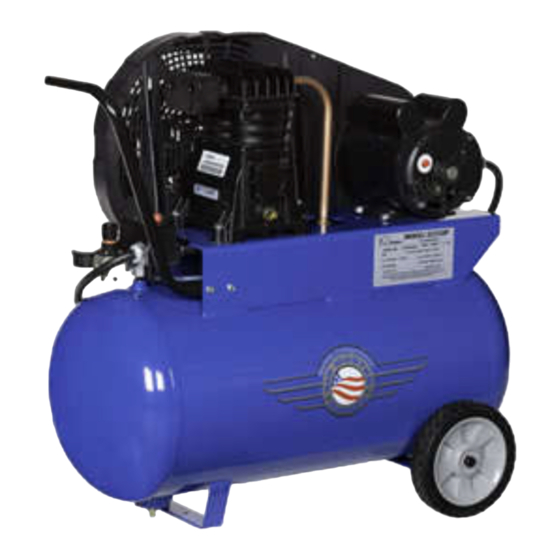
Single stage compressor
Hide thumbs
1
Table Of Contents
2
3
4
5
6
7
8
9
10
11
12
13
14
15
16
17
18
page
of
18
Go
/
18
Contents
Table of Contents
Troubleshooting
Bookmarks
Table of Contents
Table of Contents
Safety
Description & Application
Installation
System Components
Pre-Starting Checklist
Starting & Stopping the Compressor
Maintenance
Troubleshooting
Compressor Unit Parts
Decals & Dimensions
Advertisement
Quick Links
1
Table of Contents
2
Installation
3
System Components
4
Maintenance
5
Compressor Unit Parts
Download this manual
Single Stage Compressors
Instruction & Parts Manual
This manual contains important safety information and must be
carefully read in its entirety and understood prior to installation
by all personnel who install, operate and/or maintain this product.
Manual No. 1312100602
September 2012 Edition
Table of
Contents
Previous
Page
Next
Page
1
2
3
4
5
Advertisement
Table of Contents
Need help?
Do you have a question about the Q12120P and is the answer not in the manual?
Ask a question
Questions and answers
Related Manuals for Quincy Compressor Q12120P
Air Compressor Quincy Compressor Q13160V Instruction & Parts Manual
Single stage compressor (18 pages)
Air Compressor Quincy Compressor Q1214TS Instruction & Parts Manual
Direct driven single stage compressor (12 pages)
Air Compressor Quincy Compressor QSI Series Instruction Manual
Qsi series industrial rotary screw air compressors (100 pages)
Air Compressor Quincy Compressor QSI Series Instruction Manual
Fixed speed rotary screw air compressors (142 pages)
Air Compressor Quincy Compressor QR-25 Series Instruction Manual
(38 pages)
Air Compressor Quincy Compressor QR-25 Series Instruction Manual
(43 pages)
Air Compressor Quincy Compressor QR-25 Series Instruction Manual
(44 pages)
Air Compressor Quincy Compressor QED 650 Instruction And Maintenance Manual
Refrigerant compressed air dryers (99 pages)
Air Compressor Quincy Compressor QT Series Instruction Manual
(50 pages)
Air Compressor Quincy Compressor QTS Series User Manual
(20 pages)
Air Compressor Quincy Compressor QMA Series Instruction Manual
(70 pages)
Air Compressor Quincy Compressor QSI-i Series Instruction Manual
50-200 horsepower direct drive industrial air compressors (138 pages)
Air Compressor Quincy Compressor QSI 50 Instruction Book
Oil-injected rotary screw compressors (132 pages)
Air Compressor Quincy Compressor QGS 40 Instruction Book
Oil-flooded rotary screw compressors (102 pages)
Air Compressor Quincy Compressor QGD 40 Instruction Book
Oil-injected rotary screw compressors (114 pages)
Air Compressor Quincy Compressor QGS 10 Instruction Book
Oil-injected rotary screw compressors (96 pages)
This manual is also suitable for:
Q13160v
Q12126vp
Table of Contents
Save PDF
Print
Rename the bookmark
Delete bookmark?
Delete from my manuals?
Login
Sign In
OR
Sign in with Facebook
Sign in with Google
Upload manual
Upload from disk
Upload from URL


Need help?
Do you have a question about the Q12120P and is the answer not in the manual?
Questions and answers