Table of Contents
Advertisement
Quick Links
Advertisement
Table of Contents

Subscribe to Our Youtube Channel
Related Manuals for LSI Pluvi-ONE


Summary of Contents for LSI Pluvi-ONE
- Page 1 Environmental monitoring solutions Pluvi-ONE User manual...
-
Page 2: Notes On This Manual
Notes on this manual The information included in this manual may be modified without notice. No part of this manual may be reproduced in any form or by any electronic or mechanical means, for any use, without LSI LASTEM’s written permission. -
Page 3: Table Of Contents
Data delivery to FTP and MQTT server or USB memory ............20 2.2.7 Configuring logics, actuators and alarms ................21 2.2.8 Saving and uploading configuration file to Pluvi-ONE ............. 22 Connecting probes to Pluvi-ONE ..................... 23 Check measures acquisition ......................23 LSI LASTEM SRL... - Page 4 Logic assigned to a power supply output (actuator) ............37 3.1.9.2 Logic assigned to an action ....................38 3.1.10 Uploading configuration file to Pluvi-ONE ................39 3.1.10.1 Sending via SSH connection ..................... 39 3.1.10.2 Sending via USB pen drive ....................39 3.1.10.3...
- Page 5 Part 5 ........................65 Diagnostics ............................65 5.1.1 Product identification ......................65 5.1.2 Troubleshooting ........................65 Maintenance ............................ 69 Contacting LSI LASTEM ........................69 Pluvi-ONE configuration templates ................70 Technical specifications .................... 74 LSI LASTEM SRL INSTUM_02422 Page 5 / 77...
-
Page 6: How To Use This Manual
Pluvi-ONE – User manual How to use this manual Use the block diagram on the next page to browse within the different options and features. To facilitate the reading of the manual using electronic devices such as PCs, tablets and smartphones, the references to the various chapters, indicated with the “§”... -
Page 7: Flow Scheme Of The Features
Pluvi-ONE – User manual Flow scheme of the features START 1. 3DOM sw installation on PC (§2.1.1) 2. Pluvi-ONE connection to 3. Registry configuration 4. Operating mode PC and registration of its SN (§2.2.1) configuration (§2.2.2) inside 3DOM (§2.1.2.1) 7. Elaborations configuration 6. - Page 8 Pluvi-ONE – User manual 12. Logics configuration 13. SMS alarm configuration Via SMS? alarms? (§2.2.7) (§3.1.9.2) 14. Mail alarm configuration Via Mail? (§3.1.9.2) 15. Set Delivery time rate in Use Fast alarm conditions (§2.2.8) Mode? 16. MQTT parameters MQTT? configuration (§2.2.5.4) 17.
-
Page 9: Part 1
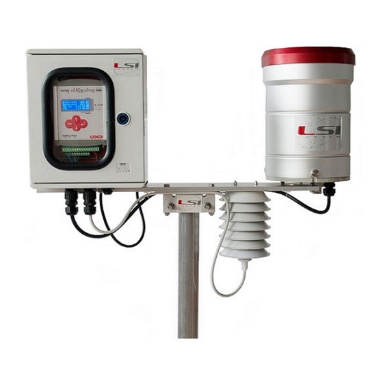
Part 1 1.1 Introduction Pluvi-ONE is an integrated system for monitoring rain and for issuing alarms. The basic system consists of a rain gauge, a data logger, a communication system and a power supply. The rain data produced are saved in its internal memory, or on a USB key, and sent via radio or via modem to appropriately configured remote systems. -
Page 10: Instrument Description
Pluvi-ONE – User manual 1.2 Instrument description (1) - On/Off switch (2) - I C input: lightning or thermo- hygrometic sensor (opt.) (3) - USB ports (4) - Ethernet port (5) - Com1 serial port (modem) (6) - Com2 serial port (service) -
Page 11: Product Setup And Disposal
1.3.2 Mechanical installation and placing Pluvi-ONE is usually used outdoor inside the appropriate protective boxes. However, indoor use is possible by fixing the instrument on DIN bar or to wall. For its functioning it requires the dedicated power supply or a photovoltaic module with the proper external battery. -
Page 12: Part 2
2.1.2 Pluvi-ONE entry in 3DOM At the first use it is necessary to insert Pluvi-ONE in the list of 3DOM instruments and import its factory configuration. This can be done by connecting to the data logger via Ethernet(4) or using a USB stick. -
Page 13: Pluvi-One Entry Via Usb Stick
2. Using the keyboard (8), enter the PEN DRIVE menu (§4.1.4.5.3). This function is accessible after about one minute since the instrument’s ignition. 3. Insert the USB stick in one of Pluvi-ONE's USB ports (8). By reference to §4.1.4.5.3: 4. Choose Upload config and press , then confirm with . -
Page 14: Configuring Pluvi-One
2.2 Configuring Pluvi-ONE In addition to the factory configuration, alternative configuration template models are available (§Pluvi-ONE configuration templates). In both cases it is usually necessary to adapt these configurations according to the specific requirements. When completed, this new configuration will be sent to the instrument, which will start operating based on the options selected. -
Page 15: Set Instrument Code, Name And Geographical Information
Pluvi-ONE. When Use a substitutive serial number=YES, this number will be used on the data file instead of the factory serial number. It is possible to set the Pluvi-ONE name and geographical information. Time zone is needed to assign the time stamp to the measurements. -
Page 16: Sensors Configuration
Pluvi-ONE – User manual 2.2.3 Sensors configuration When one of configuration models suggested by 3DOM is used, remove the sensors not used and/or to add the ones missed. To add sensors, it is possible to search inside the 3DOM sensors library: 1. -
Page 17: Configuring Internet Connectivity - Network Interfaces
2.2.4 Configuring Internet connectivity – network interfaces Services such as sending data to a FTP server, sending e-mails, managing Pluvi-ONE configuration in remote mode as well as clock synchronization, require internet connection. If you wish to use such services, you should configure the network interface (LAN or WLAN) you need to use. -
Page 18: Ppp Interface (3G/4G Modem)
Pluvi-ONE to a WLAN network. If an internet connection is required and there is no LAN or WLAN network available for Pluvi-ONE connection, use a 3G/4G modem equipped with appropriate SIM card (having activate data traffic, check the data volume) and configure PPP interface. -
Page 19: Nftp, Mqtt, Ntp Protocols Configuration
If Configuration Authority is enabled, each time the configuration is saved using 3DOM, it is also sent to the same FTP area. In concurrence with every data transfer via FTP, Pluvi-ONE monitors the FTP area that has been set up as Configuration Authority and, if it detects the presence of a new configuration file, this is automatically uploaded;... -
Page 20: Ntp Protocol For Watch Synchronization Via Internet
The password is visible in the configuration file. 2.2.6 Data delivery to FTP and MQTT server or USB memory Typically, Pluvi-ONE send data in the form of ASCII file to one FTP area inside a server From Elaboration Parameters(1). General Parameter(2). Set the rate of data... -
Page 21: Configuring Logics, Actuators And Alarms
It is possible to set logics that, upon their occurrence (true / false), will activate an action as: triggering local electrical outputs and messages (SMS, Email, MQTT). Pluvi-ONE is equipped with 3 actuated electrical outputs for triggering external devices such as sensors, modems or alarm devices. Additionally, it can also send e-mails, SMS, and MQTT messages. -
Page 22: Saving And Uploading Configuration File To Pluvi-One
Pluvi-ONE detects the irregularity and restarts itself with the last valid configuration. To send the configuration via SSH (Pluvi-ONE is connected to the PC directly via Ethernet or Wi-Fi): 1. Select the serial number of the instrument and the required configuration from the list Instruments. -
Page 23: Connecting Probes To Pluvi-One
Once the physical connection of the probes has been completed, the instantaneous values can be displayed on 3DOM. The use of the software requires that Pluvi-ONE is connected to the PC via the Ethernet or Wi-Fi port. If not, check the instantaneous values directly on the data logger display (§4.1.4.1). -
Page 24: Check Data Reception To Pc Using 3Dom Program
Pluvi-ONE – User manual If modem is used, check connectivity using the PPP menu where it is checked if the radio modem has received an IP from the mobile network, this confirms the internet connectivity of the instrument. If FTP sites have been configured, perform a connection test. - Page 25 Pluvi-ONE – User manual 2. Select the data download modality (2). ➢ From FTP site: select the FTP address from the proposed list (3). ➢ From local (network) folder: select the local folder (or network folder) […](4). 3. Select the day/time since the data are required (5).
-
Page 26: Part 3 - Insights
➢ Data configuration update: the exact date and time the instrument received data. The parameters in Device Identifier are editable. These are: ➢ Use an alternative serial code: if set on Yes, Pluvi-ONE uses Alternative serial code instead of Serial number. -
Page 27: Operating Mode Based On Energy Availability
(e.g. for sending data to the FTP site), at the expense of the communication with the external devices. When Pluvi-ONE’s power voltage is higher than the set high threshold, the data logger works in the selected operative mode (data logger status = Run normal). -
Page 28: Connectivity
Fig. 5 – Pluvi-ONE’s operating status. 3.1.3 Connectivity The communication between Pluvi-ONE and the external devices works through different network protocols. It’s therefore necessary to configure the network connection in accordance with the protocol intended to be used. 3DOM allows the user to configure the following network connections: Ethernet If configured, it permits SSH connection through a PC. - Page 29 Fig. 8 – PPP configuration for a TIM SIM example If Pluvi-ONE has connected to more than one device for its internet connection, for example a 3G / 4G modem and satellite modem, the respective gateways (routes) for internet connection must be specified as Preferred gateways.
- Page 30 Default value: 8.8.8.8. Fig. 9 – DNS server configuration example The Network Time Protocol (NTP) is a protocol used for synchronizing the Pluvi-ONE clock using the time obtained through an Internet server. The configured servers are those of the "NTP POOL PROJECT"...
-
Page 31: Serial Ports
Pluvi-ONE – User manual 3.1.4 Serial ports Pluvi-ONE provides three serial ports for the communication with external devices: two RS-232 (Com1 and Com2) and one TTL (Com4), to be used as follows: • Com1(5): for the connection to 3G/4G modem only. -
Page 32: Measurements
Input types from the Measurements acquisition section, then select and open the MODBUS RTU Master type. If it’s not present, add it with the dedicated button. ➢ Communication port: is Pluvi-ONE’s port where the Modbus RTU device is connected. Com2 connection is RS-232 type; Com3 (§Fig. 2) if it’s RS-485 type. -
Page 33: Using The Usb Memory Stick
3.1.7 Using the USB memory stick It is possible to use a USB stick as addition to the internal memory of the Pluvi-ONE or as a device for files exchanging from data logger to PC or the other way round. -
Page 34: Uso Come Dispositivo Di Scambio File
For more information on the files generated by Pluvi-ONE see §3.2.5. 3.1.7.2 Uso come dispositivo di scambio file Using the USB stick, it is possible to upload the Pluvi-ONE configuration file or to download the data files from the memory. These operations are accessible from the PEN DRIVE menu (§4.1.4.5.3). - Page 35 Pluvi-ONE – User manual Fig. 14 – Example of Threshold comparation logic. It is possible to configure the following: ➢ Name of the logic: this is the name whom it will be reported on the messages SMS, Mail and MQTT.
-
Page 36: Timer Logic
Pluvi-ONE – User manual ➢ Lower threshold: it is the value of the lower threshold; it is not available when the More than logic has been chosen. ➢ Hysteresis: it is a value that, depending on the type of comparison chosen, it is added or subtracted from the threshold values, this will avoid continuous activation/deactivation of the logic, when the measurement values are floating around the threshold. -
Page 37: Actuators And Allarms
Pluvi-ONE – User manual 3.1.9 Actuators and allarms Each logic can be assigned to an actuator (Switched power supply output) or to an action (SMS, Email, MQTT), or to both of them. 3.1.9.1 Logic assigned to a power supply output (actuator) Logics assigned to power supply output (actuator) are based on the instantaneous value of the measurements, both acquired and calculated. -
Page 38: Logic Assigned To An Action
• SMS: when the logic status occurs, Pluvi-ONE sends one SMS message to up to 5 users. The function is active only if the data logger works in low consumption mode (§3.1.2) and if a 3G / 4G modem is connected. -
Page 39: Uploading Configuration File To Pluvi-One
Fig. 18 – SSH connection to Pluvi-ONE with factory IP address example To know the Pluvi-ONE’s IP address, see §4.1.4.5.1. If the instrument does not have an IP address or it isn’t in the same network as the PC, it is possible to send the configuration through a USB pen drive or check the mode through FTP server. -
Page 40: Sending Via Ftp Server
ADVANCED FEATURES functions are active only if Advanced mode (§4.1.4.3) is enabled. 3.1.10.3 Sending via FTP server Pluvi-ONE supports FTP protocol for the file transmission in client/server mode. This type of transmission assumes the FTP server to already be configured properly. The FTP server indicated in the configuration must have a checkmark on Configuration Authorities option. -
Page 41: Insights The Pluvi-One Functionalities
Modbus Slave. 3.2.2 Internal clock/calendar Pluvi-ONE is equipped with an internal clock with backup battery. This clock is used for elaborations, alarms and system events dating and for the scheduling of other activities such as the processed files transmission on one ore more FTP servers, the measures acquisition, the actuators activation, etc. -
Page 42: Dew Point Temperature
Pluvi-ONE – User manual 3.2.3.1 Dew point temperature The calculation of the dew point temperature is based on UNI EN ISO 7726. It requires measurements of temperature and relative humidity of the air. Fig. 21 – Example of calculated measurement configuration of type "Dew point temperature"... - Page 43 Pluvi-ONE – User manual Fig. 22 – Table 3.10 reported in “International Meteorological Tables – WMO No. 188 TP. 94 - 1966” LSI LASTEM SRL INSTUM_02422 Page 43 / 77...
- Page 44 Pluvi-ONE – User manual Fig. 23 - Example of calculated measurement configuration of type "QNH - WMO Table" The type QNH - ISA, instead, uses the formula ISA nr. 7 indicated in "CIMO/ET-Stand-1/Doc. 10 (20.XI.2012)" (§ Fig. 24). Fig. 24 – Reference to equation No. 7 given in "CIMO/ET-Stand-1/Doc. 10 (20.XI.2012)"...
- Page 45 Pluvi-ONE – User manual Lastly, the type QNH - ICAO uses the formula defined by ICAO, indicated as nr. 28 and 29 in ICAO Doc 7488 and 9837, which allows to achieve results very close to the standard ISA formula (error less than 0.02 hpa up to 2000 m).
-
Page 46: Elaborations
Is like Max with the addition of the point in time when it happened Each measure can have different time basis. 3.2.5 Processed data files Data processed by Pluvi-ONE (§4.2.4), are included in text files (*.txt). Each file is identified by its name. Default name is composed as follows: Nome: CyyyyMMddhhmmss-Bnn-EyyyyMMddhhmmss.txt... -
Page 47: Header Files
C20171020081421-B00-E .txt. All files are stored in the folder named with Pluvi-ONE’s serial number. If serial number is not defined by the user, the number used will be the number defined by the factory (§3.1.1). Below is an example of files processed by Pluvi-ONE S/N 17110023. - Page 48 Pluvi-ONE – User manual ELAB] ssss,oo,zzzz [HEADER] Datetime; Serial; Latitude; Longitude; Altitude; UserSerial; SiteName; TimeZone; Name_ElElab_1_(UM)_m_1; …; Name_ElElab_n_(UM)_m_1; …; Name_ElElab_1_(UM)_m_n; …; Name_ElElab_n_(UM)_m_n; [MEASURES] Serial Latitude Longitude Altitude UserSerial SiteName TimeZone; Name_m_1; UM_m_1; ID_m_1; Prop_m_1; ListaElemElab_m_1 … Name_m_n; UM_m_n; ID_m_n; Prop_m_n; ListaElemElab_m_n...
-
Page 49: Processed Data Files
Fig. 29 – Header file example 3.2.5.2 Processed data files Data files are generated by Pluvi-ONE according to the Elaboration data delivery time parameter, specified in 3DOM’s Elaboration Parameters (§3.1.6). Default value is 1 hour. Each data file includes the date the item refers to, followed by the items as described in the header file’s HEADER section. - Page 50 Pluvi-ONE – User manual Below is an example of header files reporting metadata too: 2017-10-20T12:11:00; 17110023; 45.4558; 9.3919; 108; 17110023; Settala; 3600; 25.00 2017-10-20T12:12:00; 17110023; 45.4558; 9.3919; 108; 17110023; Settala; 3600; 25.00 2017-10-20T12:13:00; 17110023; 45.4558; 9.3919; 108; 17110023; Settala; 3600; 24.90 2017-10-20T12:14:00;...
-
Page 51: Mqtt
Every time a new message is published on that topic, the message broker delivers it to all the recipients. To enable MQTT on Pluvi-ONE use the program 3DOM. First, configure the protocol in the Connectivity section (§3.1.3). In addition to the broker parameters, activate the publication of the desired messages (instant values, processed values, diagnostic data, alarms). -
Page 52: How To Receive Data On A Smartphone
Pluvi-ONE – User manual 3.2.6.1 How to receive data on a smartphone On the market are available several apps to receive an MQTT broker’s topics. Below is an example with the app MyMQTT for Android. MyMQTT is downloadable on https://play.google.com/store/apps/details?id=at.tripwire.mqtt.client&hl=en. -
Page 53: Part 4
Pluvi-ONE – User manual Part 4 4.1 Keys, Menu and LEDs 4.1.1 Start-up/Shutdown System On/Off is controlled by the On/Off switch (5). On the start-up, the instrument shows product information and, after a few seconds, the measures list in expanded form (measure’s complete name and acquired value). Each sampled value is used to create statistics elaborations. -
Page 54: Operating Status Leds
If being hold for some seconds, turns the display off. 4.1.3 Operating status LEDs On Pluvi-ONE’s front panel are 3 LEDs that indicates the instrument operative status: Rx/Tx, Wrk, Batt. Rx/Tx This LED, green, lights up when communication activity is ongoing on any serial port. -
Page 55: Logging
Pluvi-ONE – User manual 4.1.4.1 Logging L O G G I > L a s t m e a s u r E v e n t > Last measures In this screenshot are shown, one per line, the configured measures with their last acquired or calculated value. -
Page 56: Diagnostic
Pluvi-ONE – User manual > Events This screenshot shows the circular list of the last 10 events occurred since Pluvi-ONE’s power-up. d d / M M / h h : m m : 2 8 / 0 6 / 1 2 :... - Page 57 - bbbbbbb: is the number of received messages. - ddddddd: is the number of submitted messages. > Status This screenshot shows Pluvi-ONE’s operative status. d d / M M / h h : m m : 1 8 /...
-
Page 58: System
Pluvi-ONE – User manual 4.1.4.3 System SYSTEM menu includes the command to enable Pluvi-ONE’s specific functions that are disabled if low power mode is activated. It’s also possible to display the instrument’s identification data. The menu shows up as follows: S Y S T E M >... -
Page 59: Advanced Features
D H C P R e s t c o n f > Ethernet In this screenshot are shown Ethernet port’s information that identify Pluvi-ONE in a computer network. C F G : C F G : S T A T I 1 9 2 . - Page 60 IP address. If Pluvi-ONE is connected to the network, it is possible to have its IP address assigned by the DHCP service through this mask.
- Page 61 4.1.4.5.2 Memory Pluvi-ONE is equipped with an internal memory where data and programs are stored. It’s possible to extend memory capacity by inserting a USB pen drive in one of the two available ports. The MEMORY menu allows the user to access the two types of memory, showing capacity and occupied space.
- Page 62 4.1.4.5.3 Pen drive Pluvi-ONE’s configuration and processed data can be saved on a USB pen drive. Using pen drive, it’s also possible to change instrument’s configuration. See §3.2.5 for more information on files generated by Pluvi-ONE.
- Page 63 Pluvi-ONE – User manual > Upload data files In this screenshot it’s possible to send the processed data saved in Pluvi-ONE memory to the USB pen drive. S e n d d a t U S B ? W a i o p e r o n s .
-
Page 64: Navigation Menu Structure
Pluvi-ONE – User manual 4.1.5 Navigation menu structure MAIN Logging o Last measures o Events o Errors Diagnostic o Serial lines o Status o Actuators System o Advanced mode o About… Maintenance o Suspend logging Advanced features o Connectivity ▪... -
Page 65: Part 5
Check the voltage generated by the photovoltaic panel by using a Voltmeter. Voltage must be at least 17 V for Pluvi-ONE to charge the battery. 4. If the previous points didn’t resolve the problem, there might be a hardware failure in Pluvi-ONE. LSI LASTEM SRL... - Page 66 2. Pluvi-ONE might have entered low power mode. To turn the display on press Pluvi-ONE’s keyboard button ESC (§1.2). 3. Turn Pluvi-ONE off and on. If the display won’t turn on, there could be a hardware failure in Pluvi- ONE. ❖ PC won’t communicate with Pluvi-ONE 1.
- Page 67 1. Ensure the site that the configuration was sent on has the checkmark near the Configuration Authority parameter (§2.2.5.1). 2. Ensure Pluvi-ONE is connected to the internet by running a connection test (§2.5). In case of failure, check the FTP protocol’s connectivity parameters set with 3DOM (§2.2.5.1). If they are correct, run a connection test directly from the program.
- Page 68 1. If Pluvi-ONE is powered by a power supply and does not have a battery: a. Check the wires that connect Pluvi-ONE to the power supply. One of these might be loose. b. Check the continuity of the electrical system that the equipment is connected to. In case of occasional lack of power, it’s suggested the use of a backup battery.
-
Page 69: Maintenance
5.2 Maintenance Pluvi-ONE doesn’t need special maintenance if installed as described in §1.3. However, it’s recommended to performs a periodic inspection of the entire system (Pluvi-ONE and the sensors connected), in order to detect and fix possible measurement errors. 5.3 Contacting LSI LASTEM LSI LASTEM offers its assistance service at support@lsi-lastem.com, or filling out the Request for technical... -
Page 70: Pluvi-One Configuration Templates
Pluvi-ONE – User manual Pluvi-ONE configuration templates Type 1 configuration: Rain Sensor Quantity DQA230.1 Rain Pressure (internal) Temperature (internal) Sensor Acq. rate Elaborations Pluvi-ONE Measure (UM) code hh:mm:ss (rata hh:mm – tipo) input 00:01 – Tot 00:10 – Tot 01:00 – Tot DQA230.1... - Page 71 Pluvi-ONE – User manual Type 3 configuration: Rain + level Sensor Quantity DQA230.1 Rain DMA672.3 Temperature+RH% DLE041 Soil temperature DQC001.15 Level Pressure (internal) Temperature (internal)Temperature (internal) Sensor Acq. rate Elaborations Pluvi-ONE Measure (UM) code hh:mm:ss (rata hh:mm – tipo) input 00:01 –...
- Page 72 Pluvi-ONE – User manual Common settings Registry Parameter Value Use an alternative serial code User-defined name Site name Longitude Latitude Altitude Time zone 00:00 System Parameter Value Operative mode Always on Power threshold low Power threshold high 11.8 Rows of logs to send (0 – 1000)
- Page 73 Pluvi-ONE – User manual Logics Measure (reference Name Description value) Tot Rain last 10 min beyond RAIN (Last 10 min – Logic is activated when the precipitation detected in limit Mobile tot) the last 10 minutes is higher than 16 mm Tot Rain last 60 min beyond RAIN (Last 60 min –...
-
Page 74: Technical Specifications
Pluvi-ONE – User manual Technical specifications Pluvi-ONE models Codice ELP001 - ELP001.1 Description Pluvi-ONE data logger Inputs type Terminal block Analogic inputs 1 (1 ÷ 2000 mV DC) Digital inputs RS232 ports USB ports RS485 port SDI-12 port Integrated barometric sensor... - Page 75 Pluvi-ONE – User manual Input Input UART-TTL (DMA672.1 sensor, DMA672.4 sensor when (temperature RH% ELUxxx box is used) sensor) Range Temperature: -40 ÷ 70 °C RH%: 0 ÷ 100 % Dew Point: -40 ÷ 70 °C Resolution Temperature: 0.1 °C RH%: 0 ÷...
- Page 76 Type Three levels of memorization for more reliability: • 8/16 MB on Flash chip for LSI LASTEM file system • 400 MB data on Flash chip with UBIFS file system • Up to 32 GB data on USB memory with FAT32 file system...
- Page 77 Pluvi-ONE – User manual Linux computer Type Linux based on computer with open and user extendable architecture Processor 32 Bit ADC converter 16 bit • Always ON (always connected to the Internet) Powering mode • Automatic ON (awake for data transmission only, best...
Need help?
Do you have a question about the Pluvi-ONE and is the answer not in the manual?
Questions and answers