
Subscribe to Our Youtube Channel
Related Manuals for LSI DNB105.2


Summary of Contents for LSI DNB105.2
- Page 1 Environmental monitoring solutions Ultrasonic anemometer DNB105.2 User manual Updated 04/05/2021 INSTUM_ 04371 Page 1/13...
- Page 2 Ultrasonic anemometer – User manual INSTUM_ 04371 Page 2/13...
-
Page 3: Table Of Contents
Electrical connections ........................7 2.3.1 RS485 serial connection ......................8 2.3.2 Analog Output connection ......................8 2.3.3 Connection to LSI LASTEM data logger ..................8 Configuration ............................. 9 Modbus-RTU ............................10 Maintenance ............................11 Testing ............................. 11 Periodic maintenance ........................12 Accessories / Spare parts ......................... -
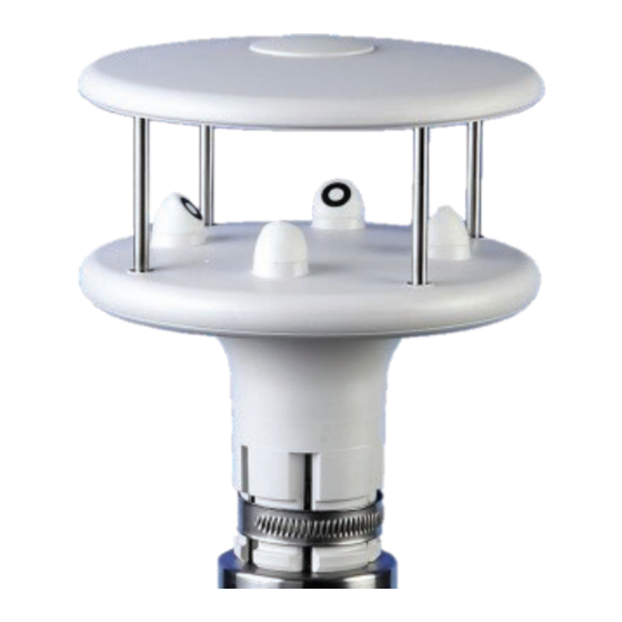
Page 4: Description
It has two 4÷20 mA analog outputs, one for wind speed and one for wind direction, and one RS485 serial output with Modbus-RTU protocol. The anemometer can be connected to LSI LASTEM acquisition systems, or any other device using such kind of input. -
Page 5: Installation
Ultrasonic anemometer – User manual 2 Installation For the installation choose a well-exposed spot for the anemometer. The WMO (World Meteorological Or- ganization) suggests that the sensor should be assembled 10 m off the ground; in a place where the dis- tance between the anemometer and surrounding obstacles which might disturb the measurements is at least 10 times the height of those objects from the ground. -
Page 6: Mechanical Installation
Ultrasonic anemometer – User manual 2.2 Mechanical installation 1. Pass the connection cable (DWA8xx.1) in- 2. Mount the anemometer side the support mast and connect the 19- on the mast (∅ 40 mm external and ∅ 36 mm in- pole M23 female connector of the cable to ternal). -
Page 7: Electrical Connections
Ultrasonic anemometer – User manual 2.3 Electrical connections All connections are performed through a 19-pole M23 male connector situated at the bottom of the ane- mometer. The figure and the table below show numbers and function of the connector contacts: Pin connector Symbol Description... -
Page 8: Rs485 Serial Connection
Association). 2.3.2 Analog Output connection OUT 1 and OUT 2 are associated to wind speed and wind direction respectively. 2.3.3 Connection to LSI LASTEM data logger For the wiring connection see the DISACC210021 supplied with the anemometer. INSTUM_ 04371 Page 8/13... -
Page 9: Configuration
Ultrasonic anemometer – User manual 3 Configuration The anemometer supplied from LSI LASTEM is ready for working with its data loggers. The table below shows its configuration. Section Parameter Value General settings Enabling magnetic compass Enabled Wind speed thresholds 0.2 (m/s) -
Page 10: Modbus-Rtu
Ultrasonic anemometer – User manual 4 Modbus-RTU The Modbus function code 04h (Read Input Registers) allows reading the values measured by the anemom- eter. The following table lists the Input Registers available. Register Quantity Format number Instantaneous wind speed (x100) unsigned 16 bits Instantaneous wind direction in degrees (x10) unsigned 16 bits... -
Page 11: Maintenance
Ultrasonic anemometer – User manual 5 Maintenance 5.1 Testing This type of testing is only required if the user wishes to verify the well functioning of each part of the anemometer. Please note that these tests are not intended to establish the operational limitations of the sensor. -
Page 12: Periodic Maintenance
The absence of moving parts minimizes the sensor maintenance. • Clean the anemometer paying attention at two pairs of transducers oriented along two orthogonal axes. LSI LASTEM suggests to check the anemometer calibration every 2 years. INSTUM_ 04371 Page 12/13... -
Page 13: Accessories / Spare Parts
(RAEE). For this reason, at the end of its life, the instrument must be kept apart from oth- er wastes. LSI LASTEM is liable for the compliance of the production, sales and disposal lines of this product, safeguarding the rights of the consumer. Unauthorized disposal of this product will be punished by the law.
Need help?
Do you have a question about the DNB105.2 and is the answer not in the manual?
Questions and answers