
Subscribe to Our Youtube Channel
Related Manuals for LSI DPA953.1


Summary of Contents for LSI DPA953.1
- Page 1 Environmental monitoring solutions DPA953.1 Secondary standard pyranometer with Modbus RTU User manual...
- Page 2 DPA953.1 – User manual Revisions list Issue Date Description of changes Origin 01/06/2023 INSTUM_04431 V 2001 Pag. 2 / 76...
-
Page 3: Cautionary Statements
DPA953.1 – User manual Cautionary statements Cautionary statements are subdivided into four categories: danger, warning, caution and notice according to the severity of the risk. DANGER Failure to comply with a danger statement will lead to death or serious physical injuries. -
Page 4: Table Of Contents
Operating modes: heating and ventilation..................19 Overview of remote diagnostics ......................20 Use of the tilt sensor ......................... 20 Specifications of DPA953.1 ........................21 Specifications of DPA953.1 ........................ 21 Dimensions of DPA953.1 ........................27 Standards and recommended practices for use..................28 Classification standards ........................ - Page 5 12 Safety ............................... 60 13 Appendices .............................. 61 13.1 Appendix on tools for DPA953.1 ....................... 61 13.2 Appendix on spare parts for DPA953.1 ..................... 61 13.3 Appendix on the ventilator ........................ 61 13.4 Appendix on standards for classification and calibration ..............62 13.5...
- Page 6 DPA953.1 – User manual 13.8 Appendix on ISO 9060:1990 classification no longer valid ..............67 13.9 Appendix on definition of pyranometer specifications ..............68 13.10 Appendix on terminology / glossary ....................70 13.11 Appendix on function codes, register and coil overview .............. 71 13.12...
-
Page 7: List Of Symbols
DPA953.1 – User manual List of symbols Quantities Symbol Unit Sensitivity V/(W/m Temperature °C Solar irradiance Plane of Array irradiance Solar radiant exposure W∙h/m Time in hours Tilt angle relative to horizontal θ ° Relative humidity Pressure Temperature coefficient 1/°C²... -
Page 8: Introduction
DPA953.1 measures the solar radiation received by a plane surface, in W/m , from a 180 field of view angle. DPA953.1 is an ISO 9060 spectrally flat Class A (previously “secondary standard”) pyranometer. It is employed where the highest measurement accuracy is required. DPA953.1 offers several advantages over competing pyranometers: •... - Page 9 See Section 2.1 in this manual for a more detailed explanation. Low cost of ownership DPA953.1 is an affordable spectrally flat Class A instrument and is designed for low cost of ownership, which is mainly determined by costs of installation, on-site inspections, servicing...
- Page 10 Brazil. Recalibration is recommended every 2 years, which is good practice in the indus- try. Liabilities covered: test certificates As required by ISO 9060 for Class A classification, each DPA953.1 is supplied with test results for the individual instrument: •...
- Page 11 Heating and ventilation may be switched on and off by digital control. If the heater is switched [OFF], DPA953.1 operates in medium power mode. Operation at < 0.1 W, in the low power mode, is possible by switching both the ventilator and heater [OFF]. Although zero offset will then increase slightly, overall performance will still comply with the spectrally flat class A classification.
- Page 12 Modbus RTU slave. SCADA systems are often implemented in photovoltaic solar energy (PV) systems and meteorological networks. Using DPA953.1 in a network is easy. Once the Modbus address and communication settings have been configured and is connected to a power supply, the instrument can be used in RS-485 networks.
-
Page 13: Ordering And Checking At Delivery
DPA953.1 – User manual 1 Ordering and checking at delivery 1.1 Included items Arriving at the customer, the delivery should include: • pyranometer DPA953.1 • sun screen • cable of the length as ordered • product certificate matching the instrument serial number, including:... -
Page 14: Instrument Principle And Theory
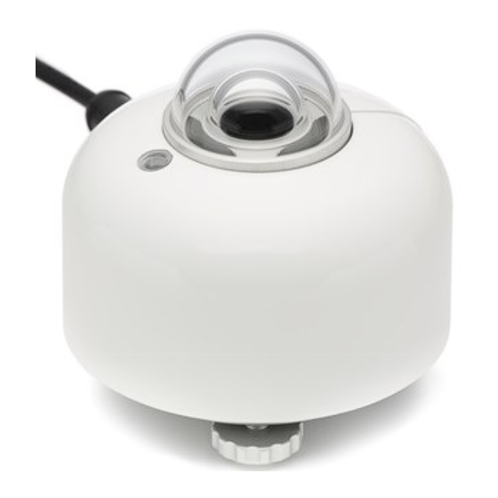
DPA953.1 – User manual 2 Instrument principle and theory Figure 2.0.1 Overview of DPA953.1: cable (standard length 5 metres, optional longer cable) connector sun screen bubble level bubble level window outer dome inner dome thermal sensor with black coating internal ventilation vents... - Page 15 DPA953.1 has a built-in heater and ventilator. The heater is attached to the sensor body. The ventilation air circulates inside the body and between the domes. The combination of ventilation and heating keeps the domes in thermal equilibrium with the thermopile sensor and above dew point.
- Page 16 DPA953.1 – User manual Pyranometers can be manufactured to different specifications and with different levels of verifi- cation and characterisation during production. The ISO 9060:2018 standard, “Solar energy - specification and classification of instruments for measuring hemispherical solar and direct solar radiation”, distinguishes between 3 classes;...
-
Page 17: Why A "Spectrally Flat" Pyranometer
DPA953.1 – User manual Figure 2.0.3 Directional response of an DPA953.1 pyranometer of 4 azimuth angles, com- pared to secondary standard limits. 2.1 Why a “spectrally flat” pyranometer? ISO 9060:2018 defines classes A, B and C. The standard also defines a subclass, called "spec- trally flat". - Page 18 DPA953.1 – User manual To conclude, specifying "spectrally flat" is essential because this ensures: • you can measure accurately not only clear-blue-sky (with direct solar radiation) GHI in a horizontal position, but also when a cloud obscures the sun, blue sky diffuse only, cloudy sky diffuse, reflected, Plane of Array, POA, for Photovoltaic solar panels, albedo or net radiation for meteorology.
-
Page 19: Operating Modes: Heating And Ventilation
DPA953.1 – User manual 2.2 Operating modes: heating and ventilation A unique feature of DPA953.1 is its built-in heater and ventilator. In practice, this is as effective against dew and frost deposition as using traditional ventilation systems. The heater is attached to the sensor body. Heat is generated inside the sensor body. The ven- tilator circulates air inside the body and between the domes. -
Page 20: Overview Of Remote Diagnostics
2.4 Use of the tilt sensor DPA953.1 is equipped with an internal tilt sensor. The tilt measurement serves to monitor slow, long-term changes as well as incidents that cause the instrument to move. The absolute accu- racy of the sensor depends on temperature and is not as high as that of the bubble level. The bubble level remains the reference for horizontal installation. -
Page 21: Specifications Of Dpa953.1
DPA953.1 – User manual 3 Specifications of DPA953.1 3.1 Specifications of DPA953.1 DPA953.1 measures the solar radiation received by a plane surface from a 180 field of view angle. This quantity, expressed in W/m , is called “hemispherical” solar radiation. DPA953.1 offers irradiance in W/m as a digital output. - Page 22 DPA953.1 – User manual Table 3.1.1 Specifications of DPA953.1 (continued on next pages) NOTICE This manual supports model DPA953.1, the successor of DPA953. Need support for the discontinued DPA953? Please refer to its separate manual. DPA953.1 ADDITIONAL SPECIFICATIONS Spectral range...
- Page 23 DPA953.1 – User manual Table 3.1.1 Specifications of DPA953.1 (started on previous pages) Tilt sensor detection limit < 0.1 ° (smallest meaningfully detectable change in a time interval of < 10 min) Tilt sensor characterisation of individual report included instrument...
- Page 24 DPA953.1 – User manual Table 3.1.1 Specifications of DPA953.1 (started on previous pages) STANDARD OPERATING MODE Operating mode heater [ON] and ventilator [ON] Zero offset a < 2 W/m Supply voltage range 8 to 30 VDC Power consumption < 3.0 W at 12 VDC...
- Page 25 DPA953.1 – User manual Table 3.1.1 Specifications of DPA953.1 (started on previous pages) Communication protocol Modbus Transmission mode BAUD rate settings 9600, 19200, 38400, 115200 Data bits Eight Parity bits None, even, odd Stop bits Default serial settings 19200 bits/s, eight data bits, even parity, one stop bit...
- Page 26 (two M5x30 and two M5x45) included allowing tilt adjustment to 3.4 requires 4 mm hex key for mounting and 4 mm hex key or 10 mm spanner for connecting to DPA953.1 option code = TLM01 Other mounting options PMF series mounting fixtures...
-
Page 27: Dimensions Of Dpa953.1
DPA953.1 – User manual 3.2 Dimensions of DPA953.1 Figure 3.2.1 Dimensions of DPA953.1 in x 10 m. Mounts are optional INSTUM_04431 V 2001 Pag. 27 / 76... -
Page 28: Standards And Recommended Practices For Use
DPA953.1 – User manual 4 Standards and recommended practices for use Pyranometers are classified according to the ISO 9060 standard and the WMO-No. 8 Guide. In any application the instrument should be used in accordance with the recommended practices of ISO, IEC, WMO and / or ASTM. -
Page 29: Specific Use For Outdoor Pv System Performance Testing
– guidelines for measurement, data ex- Reporting Photovoltaic Non-Concentrator change and analysis System Performance DPA953.1 complies, in its standard configuration, with the IEC 61724-1:2017 requirements of Class COMMENT: confirms that a pyranometer is the pre- A and Class B PV monitoring systems ferred instrument for outdoor PV testing. -
Page 30: General Use For Sunshine Duration Measurement
DPA953.1 – User manual 4.5 General use for sunshine duration measurement According to the World Meteorological Organization (WMO, 2003), sunshine duration during a given period is defined as the sum of that sub-period for which the direct solar irradiance ex- ceeds 120 W/m . -
Page 31: Installation Of Dpa953.1
DPA953.1 – User manual 5 Installation of DPA953.1 5.1 Site selection and mechanical installation Table 6.1.1 Recommendations for installation of pyranometers (continued on next page) Location the horizon should be as free from obstacles as possible. Ideally, there should be no objects be- tween the course of the sun and the instrument. - Page 32 Table 6.1.1 Recommendations for installation of pyranometers (started on previous page) Cable lengths Do not directly connect cables longer than 20 meters to DPA953.1. Whenever connection to a longer cable is re- quired, connect the instrument to that cable through a suitable isolated interface (i.e. power and signal isola- tion, e.g.
-
Page 33: Installation Of The Sun Screen
The quick release system of DPA953.1’s sun screen allows for easy and secure mounting and removal of the sun screen on the sensor. DPA953.1’s bubble level can be inspected at all times, even with the sun screen installed: a small window allows to see the bubble level. Installation and removal of the connector can be done after removal of the sun screen. -
Page 34: Installation Of Optional Mounts
The optional levelling mount, for simplified mounting and levelling of DPA953.1 on a flat surface such as a platform or bracket, is easy to use. It can be fitted to DPA953.1 using the mount’s spring-loaded centre bolt and a 4 mm hex key or a 10 mm spanner. It can be mounted on a flat surface by inserting two M5 bolts (not included) in the designated holes. - Page 35 The levelling mount is spring-loaded. Once DPA953.1 is connected and locked to the levelling mount, DPA953.1 can be levelled by the user, judging the bubble level. Levelling is done by fastening or loosening DPA953.1’s two adjustable levelling feet by hand. DPA953.1’s static foot remains fixed.
-
Page 36: Tube Levelling Mount
(on the right) DPA953.1’s two adjustable feet, DPA953.1 can be levelled, judging by the bubble level. DPA953.1’s static foot remains fixed. In all cases, ensure the legs of DPA953.1 fit into one of the small ledges of the levelling mount. Locking is in place, when the nut is turned all the way against the bottom plate of DPA953.1... -
Page 37: Electrical Installation
For reliable operation it is important to follow the installation instructions and recommendation in this section carefully. The wiring of DPA953.1 is explained in Figures 5.4.1 and 5.4.2 and Table 5.4.1. On a coarse level DPA953.1 can be viewed as having three electrical ports: a DC power port, a signal port and an enclosure port. -
Page 38: Internal Protection
5.1 Internal protection DPA953.1 electronics are internally protected to improve reliability and reduce the risk of dam- age. See the Specifications chapter for the full list of protection levels. The following protection measures are in place on the power supply wiring: •... -
Page 39: Connecting To An Rs-485 Network
DPA953.1 is designed for use in a two-wire (half-duplex) RS-485 network. In such a network, DPA953.1 acts as a slave device, responding to data requests from the master device. An RS- 485 network (or bus), consists of a twisted wire pair for data transmission plus a signal ground wire. - Page 40 DPA953.1 – User manual [data-] lines. According to the RS-485 standard, termination resistors have a value of 120 Ω and no more and no less than two line termination resistors should be installed in a single network. Failure to install line termination resistors may lead to signal reflections which could compromise signal integrity.
-
Page 41: Electrical Isolation, Grounding And Shield Connection
5.3.1 Spatially extended installations (total cable lengths >5 m) To avoid exposure of the DPA953.1 to large electrical currents or voltages caused by ground potential differences, electrical isolation and grounding is an important point of attention in the installation design. -
Page 42: Spatially Compact Installations (Total Cable Lengths ≤5 M)
An example is a point-to-point network were a single DPA953.1 is directly connected to a data- logger using the standard 5 m cable supplied with the pyranometer, with no other nodes on the network. - Page 43 DPA953.1 – User manual • The wire gauge (AWG) of the power wires, the corresponding electrical resistance of those wires and the resulting voltage drop. If the voltage drop is too large proper sensor operation may be impaired. • The use of longer cables results in more pick-up and thus more noise on the RS-485 network, which can cause communication to fail.
-
Page 44: Connecting To A Pc
DPA953.1 – User manual 5.5 Connecting to a PC DPA953.1 can be accessed and controlled using a Personal Computer (PC). In this case commu- nication with the sensor is most easily done through the user interface supplied with the instru- ment: the LSI Lastem Sensor Manager software. -
Page 45: Communication With Dpa953.1
Once the desired device address and serial communication settings have been set, DPA953.1 can be connected to an RS-485 network and a power supply (see Chapter 5). In- stalling an DPA953.1 in an RS-485 network also requires configuring the Modbus communication for this new Modbus RTU device. -
Page 46: Changing The Device Address And Serial Communication Settings
A maximum of five 16 bit Modbus registers may be read in a single request. In case six or more registers are read in one request, DPA953.1 will not respond. If the user needs the content of six or more registers, multiple request cycles must be performed. - Page 47 DPA953.1 – User manual REGISTER PARAMETER DESCRIPTION OF ACCESS FORMAT OF ADDRESS CONTENT DATA Device address Sensor address Modbus network, de- fault = 1 Serial communication Sets the serial com- munication, see ta- settings ble 6.3.2, default = Table 6.3.2: Specification of the serial communication settings in register 0x0001...
-
Page 48: Use Of Remote Diagnostics
The sensor signal serves to externally monitor the DPA953.1 temperature and, at the same time, is used by the internal electronics for temperature correction of the measurands. The temperature dependence of the irradiance signal of every individual instrument is tested. -
Page 49: Tilt Angle
Plane of Array. 7.4 Internal relative humidity When the DPA953.1 accumulates too much moisture, the internals of the sensor will get dam- aged. Therefore, it is advised to take regular measurements of the internal relative humidity of the sensor. -
Page 50: Ventilator Speed
DPA953.1 – User manual used as a binary [ON]/[OFF] indicator, solely to determine the actual ventilator state inde- pendently. 7.7 Ventilator speed The fan speed gives the actual rotation frequency of the fan in RPM (revolutions per minute), irrespective of whether it is switched on or off. The nominal ventilator speed is 7400 RPM at 20 °C. -
Page 51: Making A Dependable Measurement
* defined by LSI Lastem as all factors outside the instrument that are relevant to the measure- ment such as the cloud cover (presence or absence of direct radiation), sun position, the local horizon (which may be obstructed) or condition of the ground (when tilted). -
Page 52: Reliability Of The Measurement
DPA953.1 – User manual 8.2 Reliability of the measurement A measurement is reliable if it measures within required uncertainty limits for most of the time. We distinguish between two causes of unreliability of the measurement: • related to the reliability of the pyranometer and its design, manufacturing, calibration (hardware reliability). -
Page 53: Speed Of Repair And Maintenance
3) A separate estimate has to be entered to allow for estimated uncertainty due to the instrument maintenance level. 4) The calibration uncertainty has to be entered. Please note that LSI Lastem calibration uncertainties are lower than those of alternative equipment. These uncertainties are en- tered in measurement equation (equation is usually Formula 0.1: E = U/S), either as an... - Page 54 DPA953.1 – User manual 6) In uncertainty analysis for modern pyrheliometers: tilt angle dependence often is so low that one single typical observation may be sufficient. 7) In case of special measurement conditions, typical specification values are chosen. These should for instance account for the measurement conditions (shaded / unshaded, venti- lated/ unventilated, horizontal / tilted) and environmental conditions (clear sky / cloudy, working temperature range).
-
Page 55: Calibration Uncertainty
DPA953.1 – User manual Estimates of achievable uncertainties of measurements with pyranometers. The Table 8.4.1.1 estimates are based on the ISO 9060:2018 specification limits, (tolerance intervals including guard bands) and a calibration uncertainty of 1.5 %, for sunny, clear sky days and well main- tained stations, without uncertainty loss due to lack of maintenance and due to instrument fouling. -
Page 56: Maintenance And Trouble Shooting
9 Maintenance and trouble shooting 9.1 Recommended maintenance and quality assurance DPA953.1 can measure reliably at a low level of maintenance in most locations. Usually unreli- able measurements will be detected as unreasonably large or small measured values. As a gen-... -
Page 57: Trouble Shooting
ISO 9847. For sensitivity adjust- ment and writing the calibration history data via a PC using the LSI Lastem Sensor Manager software, please refer to the LSI Lastem Sensor Manager manual for instructions. - Page 58 Default settings upon delivery are listed in section 3.1. If settings are not known use the LSI Lastem Sensor Manager. Connect sensor to a PC and perform a search oper- ation with the Sensor Manager to determine the pyranometer’s device address and serial communication settings.
-
Page 59: Calibration And Checks In The Field
Ask LSI Lastem for information on ISO and ASTM standardised procedures for field calibration. For sensitivity adjustment and writing the calibration history data via a PC using the LSI Lastem Sensor Manager software, please refer to the LSI Lastem Sensor Manager manual for instructions. -
Page 60: Data Quality Assurance
(WEEE). It is therefore not to be collected with any other kind of waste. LSI LASTEM is liable for the compliance of the production, sales and disposal lines of the product, safeguarding the rights of the consumer. Unauthorized disposal will be punished by the law. Dispose of the dead batteries according to the regulations in force. -
Page 61: Appendices
NOTE: Outer dome, bubble level, thermopile sensor and internal sensors of DPA953.1 cannot be supplied as spare parts. In case of damage to the DPA953.1, after repair the instrument must be tested to verify performance within specification limits. This is required by ISO 9060. Testing involves verification of the directional response after dome, printed circuit board and thermal sensor replacement;... -
Page 62: Appendix On Standards For Classification And Calibration
World Radiometric Reference. See www.pmodwrc.ch. The LSI Lastem standard is traceable to an outdoor WRR calibration. Some small corrections are made to transfer this calibration to the LSI Lastem standard conditions: sun at zenith and 1000 INSTUM_04431 V 2001... - Page 63 (transfer error). The coverage factor must be deter- mined; at LSI Lastem we work with a coverage factor k = 2. INSTUM_04431 V 2001 Pag.
-
Page 64: Appendix On Meteorological Radiation Quantities
W∙h/m Table 10.6.1 Meteorological radiation quantities as recommended by WMO (additional symbols by LSI Lastem Thermal Sensor). POA stands for Plane of Array irradiance. The term originates from ASTM and IEC standards. -
Page 65: Appendix On Iso And Wmo Classification Tables
Table 10.7.1 Valid classification table for pyranometers per ISO 9060:2018 and WMO. NOTE: WMO specification of spectral selectivity is different from that of ISO. LSI Lastem conforms to the ISO limits. WMO also specifies expected accuracies. ISO finds this not to be a part of the classification system because it also involves calibration. - Page 66 DPA953.1 – User manual ADDITIONAL WMO SPECIFICATIONS WMO CLASS HIGH QUALITY GOOD QUALITY MODERATE QUALITY WMO: achievable accuracy for daily sums* 10 % WMO: achievable accuracy for hourly sums* 20 % WMO: achievable accuracy for minute sums* not specified not specified...
-
Page 67: Appendix On Iso 9060:1990 Classification No Longer Valid
(c) daily exposure values are for clear days at mid-latitudes. WMO 7.3.2.5: Table 7.5 lists the expected maximum deviation from the true value, excluding calibration errors. ** At LSI Lastem the expression ± 1 % is used instead of a range of 2 %. INSTUM_04431 V 2001 Pag. -
Page 68: Appendix On Definition Of Pyranometer Specifications
DPA953.1 – User manual *** ISO 9060:1990 an instrument is subject to conformity testing of its specifications. Depending on the classification, conformity compliance can be proven either by group- or individual compliance. A specifica- tion is fulfilled if the mean value of the respective test result does not exceed the corresponding limiting value of the specification for the specific category of instrument. - Page 69 DPA953.1 – User manual Clear sky global maximum spectral error observed for a set of global horizontal ISO 9060:2018 irradiance clear sky spectra defined in this horizontal irradi- document ISO 9060:2018 ance spectral er- Temperature percentage deviation of the sensitivity due to change in am- ISO 9060:2018 bient temperature within the interval of –...
-
Page 70: Appendix On Terminology / Glossary
DPA953.1 – User manual 13.10 Appendix on terminology / glossary Table 10.10.1 Definitions and references of used terms (continued on next page) TERM DEFINITION (REFERENCE) Solar energy solar energy is the electromagnetic energy emitted by the sun. Solar energy is also or solar called solar radiation and shortwave radiation. -
Page 71: Appendix On Function Codes, Register And Coil Overview
NOTICE Depending on processing by the network master, your data request may need an offset of +1 for each DPA953.1 register address. Example: DPA953.1 register ad- dress 7 + master offset = 7 + 1 = master register address 8. - Page 72 DPA953.1 – User manual Table 10.11.2 Modbus registers 0 to 199 (continued on next pages) MODBUS REGISTERS 0-199 REGISTER PARAMETER DESCRIPTION OF ACCESS FORMAT OF ADDRESS CONTENT DATA Device address Sensor address in Modbus network, default = 1 Serial communication...
- Page 73 DPA953.1 – User manual MODBUS REGISTERS 0 – 199, continued REGISTER REGISTER REGISTER REGISTER REGISTER ADDRESS ADDRESS ADDRESS ADDRESS ADDRESS 48 to 60 Factory use Firmware version Hardware version 63 + 64 Sensor sensitivity In x 10 V/(W/m Float history 1...
- Page 74 NOTICE Depending on processing by the network master device, your data request may need an offset of +1 for each DPA953.1 register address. If so, this offset applies to coils as well. Consult the manual of the network master device.
-
Page 75: Appendix On Electromagnetic Compatibility (Emc) Testing
DPA953.1 – User manual 13.12 Appendix on electromagnetic compatibility (EMC) testing EMC testing has been performed according to the following standards: • Emission IEC/EN 61326-1 (2013) • Immunity IEC/EN 61326-1 (2013) Table 10.12.1 Immunity test descriptions and basic test standards used for EMC testing... - Page 76 www.lsi-lastem.com...
Need help?
Do you have a question about the DPA953.1 and is the answer not in the manual?
Questions and answers