Sign In
Upload
Download
Table of Contents
Contents
Add to my manuals
Delete from my manuals
Share
URL of this page:
HTML Link:
Bookmark this page
Add
Manual will be automatically added to "My Manuals"
Print this page
×
Bookmark added
×
Added to my manuals
Manuals
Brands
RTI Manuals
Amplifier
AD-46-100
Installation & operation manual
RTI AD-46-100 Installation & Operation Manual
4x6, 8x10 dsp matrix amplifier
Hide thumbs
1
Table Of Contents
2
3
4
5
6
7
8
9
10
11
12
13
14
15
16
17
18
19
20
21
22
23
24
25
26
27
28
29
30
31
32
33
34
35
36
37
38
39
40
41
42
43
44
45
46
47
48
49
50
page
of
50
Go
/
50
Contents
Table of Contents
Bookmarks
Table of Contents
Table of Contents
Introduction
Features
Package Contents
Panel Description
Installation
Rack Installation
Cabinet / Shelf Installation
Connections
Power
Control Interfaces
Source Audio Inputs
Speaker Outputs
Web Interface
Login
Dashboard
Sources (Basic)
Sources Advanced
Zones (Basic)
Zones (Advanced)
Grouping
Eq Setting
Configure
Applications
Four 2.1 Audio Zones
Independent Outdoor Landscape And Dedicated 2 Channel Listening Zone
Safety Suggestions
Cleaning
Federal Communications Commission Notice
Industry Canada Compliance Statement
Declaration Of Conformity (Doc)
Contacting Rti
Service & Support
Limited Warranty
Disclaimer
Advertisement
Quick Links
1
Web Interface
2
Login
3
Configure
Download this manual
Installation & Operation Guide
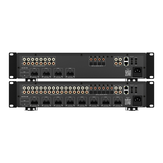
RTI DSP Matrix Amplifiers
AD-46-100
- 4 x 6 DSP Matrix Amplifier - 100W
AD-810-100 - 8 x 10 DSP Matrix Amplifier - 100W
Version 1.0
Table of
Contents
Previous
Page
Next
Page
1
2
3
4
5
Advertisement
Table of Contents
Need help?
Do you have a question about the AD-46-100 and is the answer not in the manual?
Ask a question
Questions and answers
Subscribe to Our Youtube Channel
Related Manuals for RTI AD-46-100
Amplifier RTI AD-4 Installation And Operation Manual
(36 pages)
Amplifier RTI AD-4x Installation And Operation Manual
(40 pages)
Amplifier RTI AMR-350 User Manual
Mini audio amplifier (28 pages)
Amplifier RTI AMR-350 Reference Manual
3x1 audio mixer amplifier (2 pages)
Amplifier RTI AMV-340 User Manual
40 watt power amplifier (24 pages)
Amplifier RTI AMV-340 Reference Manual
3x1 audio mixer amplifier (2 pages)
Amplifier RTI AMR-220 Reference Manual
2x1 audio mixer amplifier (2 pages)
Amplifier RTI AD-810-100 Installation & Operation Manual
4x6, 8x10 dsp matrix amplifier (50 pages)
Amplifier RTI AMP-4-125 Installation And Operation Manual
Commercial amplifiers (27 pages)
Amplifier RTI Cool Power CP-16i Installation And Operation Manual
(28 pages)
Amplifier RTI CP-1650 Installation & Operation Manual
Cool power audio amplifier (28 pages)
Amplifier RTI Cool Power CP-450 Installation And Operation Manual
Cool power audio amplifier (28 pages)
Amplifier RTI VHX-4 Reference Manual
4x4 hdmi video matrix (2 pages)
Amplifier RTI VDA-14 Reference Manual
1x4 video distribution amplifier (2 pages)
Amplifier RTI VMX-16 Reference Manual
16x16 modular video matrix (2 pages)
This manual is also suitable for:
Ad-810-100
Table of Contents
Print
Rename the bookmark
Delete bookmark?
Delete from my manuals?
Login
Sign In
OR
Sign in with Facebook
Sign in with Google
Upload manual
Upload from disk
Upload from URL


Need help?
Do you have a question about the AD-46-100 and is the answer not in the manual?
Questions and answers