Table of Contents
Advertisement
Quick Links
Advertisement
Chapters
Table of Contents

Related Manuals for Signature Kitchen Suite SKSCF1811P


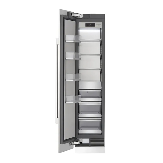
Summary of Contents for Signature Kitchen Suite SKSCF1811P
- Page 1 Guida all’installazione del frigorifero integrato FRIGORIFERO DA INCASSO SKSCF1811P SKSCF2411P SKSCR2411P SKSCF3011P SKSCR3011P SKSCW182RP SKSCW242RP www.signaturekitchensuite.com MFL67410832_Rev.01 Copyright © 2021 SIGNATURE KITCHEN SUITE. All Rights Reserved.
-
Page 2: Table Of Contents
Preparare il collegamento del tubo dell’acqua ....47 INTEGRATA Collegare il tubo dell’acqua ..........47 SKSCW242RP – 24" COLONNA VINO INTEGRATA ..18 Attaccare il logo SIGNATURE KITCHEN SUITE ....48 SKSCF3011P – 30" COLONNA CONGELATORE INTEGRATA SKSCR3011P – 30" COLONNA FRIGORIFERO INTEGRATA ..............20... -
Page 3: Istruzioni Per La Sicurezza
ISTRUZIONI PER LA SICUREZZA ISTRUZIONI IMPORTANTI SULLA SICUREZZA La presente guida contiene molti messaggi importanti sulla sicurezza. Leggere e osservare sempre tutti i messaggi sulla sicurezza. Questo è il simbolo di avviso sulla sicurezza. Ti avvisa di messaggi sulla sicurezza che ti informano dei rischi che possono uccidere o ferire te o altri o causare danni al prodotto. -
Page 4: Connessione Elettrica
• Installare il prodotto su una superficie solida e piana che possa sostenerne il peso senza piegarsi. Il prodotto deve essere messo a livello sia in orizzontale che in verticale. • Tenere i bambini lontani dall’area durante l’installazione. • Non usare prolunghe o prese multiple con questo prodotto. •... - Page 5 Dare al compressore il tempo di circolare prima di riavviare. Per evitare rischi, se il cavo è danneggiato deve essere sostituito dal produttore, dal suo agente del servizio o da altro personale qualificato. ATTENZIONE Non rimuovere il coperchio del distributore automatico di ghiaccio. Il meccanismo interno del fabbricatore di ghiaccio può...
-
Page 6: Prima Dell'installazione
Prima dell’installazione AVVERTENZA Non conservare o installare l’elettrodomestico in luoghi in cui sarebbe esposto a: • agenti atmosferici • infiltrazioni d’acqua • temperature sotto i 0°C (32°F) Scegliere la posizione di installazione Temperature e umidità L’elettrodomestico deve essere installato in un’area asciutta e ben ventilata. Per evitare malfunzionamenti, la temperatura ambiente deve essere tra i 13°C e i 43°C (55°F - 110°F). -
Page 7: Alloggiamento
Alloggiamento • Il pannello sopra l’elettrodomestico deve essere fatto di materiale solido (non MDF) che sia spesso almeno 16 mm. • Le pareti laterali della cavità o alloggiamento devono essere incassate. • I 100 mm anteriori della superficie interna del mobile saranno visibili quando gli sportelli sono aperti. -
Page 8: Messa A Terra
Messa a terra Il presente elettrodomestico deve essere messo a terra. Nel caso di malfunzionamento o guasto, la messa a terra ridurrà il rischio di scosse elettriche fornendo un percorso di minore resistenza per la corrente elettrica. AVVERTENZA: una connessione scorretta del conduttore di messa a terra dell’attrezzatura può... -
Page 9: Opzioni Di Installazione
Opzioni di installazione Ci sono molte diverse opzioni di installazione, limitate solo dal design della cucina. Elettrodomestico indipendente Fianco a fianco (coppia) Elettrodomestico indipendente con partizione Spessore minimo della partizione 16 mm 1 1/4" 7 7/8" (32 mm) (200 mm) *1 9/16”... -
Page 10: Skscf1811P - 18" Colonna Congelatore Integrata
SKSCF1811P – 18" COLONNA CONGELATORE INTEGRATA SKSCW182RP – 18" COLONNA VINO INTEGRATA DIMENSIONI SEZIONE – INSTALLAZIONE A INCASSO O INDIPENDENTE, COLONNA SINGOLA 18" (457 mm) 18" (457 mm) larghezza finita larghezza finita 25"(635 mm) 25"(635 mm) 4" 4" profondità min. - Page 11 Tale distanza varia in base alla maniglia utilizzata. Quando si utilizzano maniglie Signature Kitchen Suite o il kit di pannello per la porta in acciaio inox Signature Kitchen Suite con maniglia (accessori opzionali), la distanza dalla maniglia...
-
Page 12: Skscf2411P - 24" Colonna Congelatore Integrata
SKSCF2411P – 24" COLONNA CONGELATORE INTEGRATA SKSCR2411P – 24" COLONNA FRIGORIFERO INTEGRATA SKSCW242RP – 24" COLONNA VINO INTEGRATA DIMENSIONI SEZIONE – INSTALLAZIONE A INCASSO O INDIPENDENTE, CLONNA SINGOLA 24" (610 mm) 24" (610 mm) larghezza finita larghezza finita 25" (635 mm) 25"... - Page 13 Tale distanza varia in base alla maniglia utilizzata. Quando si utilizzano maniglie Signature Kitchen Suite o il kit di pannello per la porta in acciaio inox Signature Kitchen Suite con maniglia (accessori opzionali), la distanza dalla maniglia...
-
Page 14: Skscf3011P - 30" Colonna Congelatore Integrata
SKSCF3011P – 30" COLONNA CONGELATORE INTEGRATA SKSCR3011P – 30" COLONNA FRIGORIFERO INTEGRATA DIMENSIONI SEZIONE – INSTALLAZIONE A INCASSO O INDIPENDENTE, CO- LONNA SINGOLA 30" (762 mm) 30" (762 mm) larghezza finita larghezza finita 4" 4" 25" (635 mm) 25" (635 mm) (102 mm) (102 mm) profondità... - Page 15 Tale distanza varia in base alla maniglia utilizzata. Quando si utilizzano maniglie Signature Kitchen Suite o il kit di pannello per la porta in acciaio inox Signature Kitchen Suite con maniglia (accessori opzionali), la distanza dalla maniglia...
-
Page 16: Skscf1811P - 18" Colonna Congelatore Integrata
SKSCF1811P – 18" COLONNA CONGELATORE INTEGRATA SKSCW182RP – 18" COLONNA VINO INTEGRATA DIMENSIONI DEL PANNELLO PERSONALIZZATO DA 19 MM – INSTALLAZIONE A INCASSO Colonna congelatore/frigorifero COLONNA SINGOLADOPPIA COLONNA DA 18" E 24" DOPPIA COLONNA DA 18" E 30" 17 3/4"... - Page 17 NOTE Gli stipiti sono ideati per essere personalizzati con pannelli decorativi. Sono richiesti pannelli dello sportello personalizzati installabili sul campo da 19 mm. Per i pannelli personalizzati: utilizzare sagome fornite con unità per fori pre-impostati per montare le staffe del pannello (fornite con l’unità). Con l’unità sono fornite anche viti di regolazione e istruzioni. Il peso massimo totale del pannello dello sportello per una colonna da 30"...
-
Page 18: Skscf2411P - 24" Colonna Congelatore Integrata
SKSCF2411P – 24" COLONNA CONGELATORE INTEGRATA SKSCR2411P – 24" COLONNA FRIGORIFERO INTEGRATA SKSCW242RP – 24" COLONNA VINO INTEGRATA DIMENSIONI DEL PANNELLO PERSONALIZZATO DA 19 MM – INSTALLAZIONE A INCASSO Colonna congelatore/frigorifero COLONNA SINGOLA DOPPIA COLONNA DA 24" E 24" DOPPIA COLONNA DA 24" E 30" 23 3/4"... - Page 19 NOTE Gli stipiti sono ideati per essere personalizzati con pannelli decorativi. Sono richiesti pannelli dello sportello personalizzati installabili sul campo da 19 mm. Per i pannelli personalizzati: utilizzare sagome fornite con unità per fori pre-impostati per montare le staffe del pannello (fornite con l’unità). Con l’unità sono fornite anche viti di regolazione e istruzioni. Il peso massimo totale del pannello dello sportello per una colonna da 30"...
-
Page 20: Skscf3011P - 30" Colonna Congelatore Integrata
SKSCF3011P – 30" COLONNA CONGELATORE INTEGRATA SKSCR3011P – 30" COLONNA FRIGORIFERO INTEGRATA DIMENSIONI DEL PANNELLO PERSONALIZZATO DA 19 MM – INSTALLAZIONE A INCASSO COLONNA SINGOLA DOPPIA COLONNA DA 30" E 30" 29 3/4" 29 3/4" 59 3/4" (1 518 mm) 59 3/4"... - Page 21 ACCESSORI OPZIONALI – INSTALLAZIONE A INCASSO O INDIPENDENTE SKSPK300CS/SKSPK305CS – KIT PANNELLO IN ACCIAIO INOX PER COLONNA CONGELATORE/FRIGORIFERO DA 30" Questa unità può essere installata con un kit pannello in acciaio inox opzionale. Il kit include un pannello porta, uno zoccolo e una maniglia. Questo kit è...
- Page 22 • Nastro adesivo • Un ulteriore kit di unificazione è disponibile Metro a nastro metallico, come accessorio (numero parte SKSFJ800P) riga pieghevole da Signature Kitchen Suite. Squadra Livella, lunghezza 60 cm e 1,2 m Sega per tagliare gli stipiti superiori (solo per installa-...
-
Page 23: Installazione
Installazione Le seguenti istruzioni di installazione descrivono le fasi di installazione per i vari tipi di elettrodomestico: • Unità frigorifero con erogatore d’acqua • Unità congelatore con macchina del ghiaccio I diagrammi possono rappresentare in maniera generale l’elettrodomestico del cliente. Si fa riferimento in particolare agli speciali passi di installazione per singoli tipi di elettrodomestico. -
Page 24: Disimballaggio
Disimballaggio AVVERTENZA Per evitare gravi lesioni o danni al prodotto: • NON aprire lo sportello dell’elettrodomestico a meno che il prodotto non sia protetto dal ribaltamento. • L’elettrodomestico è molto pesante e tende a ribaltarsi se non è fissato. • Per evitare lesioni, impiegare almeno 2 persone e usare tecniche di sollevamento adeguate quando si solleva o si sposta l’elettrodomestico. -
Page 25: Spostare L'elettrodomestico
Spostare l'elettrodomestico AVVERTENZA • Per evitare lesioni, impiegare almeno 2 persone e osservare tecniche di sollevamento adeguate quando si solleva o si sposta l’elettrodomestico. • Se non è possibile trasportare l’elettrodomestico in posizione verticale, trasportarlo in orizzontale. Per evitare danni al prodotto: •... -
Page 26: Dimensioni Del Prodotto
Dimensioni del prodotto Colonna congelatore/vino da 18" 24 3/4"* (629 mm) 24 3/4"* (629 mm) *Profondità con pannello dello *Profondità con pannello dello VISTA FRONTALE VISTA sportello da 3/4" (19 mm) sportello da 3/4" (19 mm) LATERALE 23 7/8"** (607 mm) 23 7/8"** (607 mm) **Profondità... - Page 27 Colonna congelatore/frigorifero/vino da 24" VISTA VISTA 24 3/4"* (629 mm) 24 3/4"* (629 mm) *Profondità con pannello dello sportello *Profondità con pannello dello sportello FRONTALE LATERALE da 3/4" (19 mm) da 3/4" (19 mm) 23 7/8"** (607 mm) 23 7/8"** (607 mm) **Profondità...
- Page 28 Colonna congelatore/frigorifero da 30" VISTA VISTA 24 3/4"* (629 mm) 24 3/4"* (629 mm) *Profondità con pannello dello sportello *Profondità con pannello dello sportello FRONTALE LATERALE da 3/4" (19 mm) da 3/4" (19 mm) 23 7/8"** (607 mm) 23 7/8"** (607 mm) **Profondità...
-
Page 29: Installare Le Staffe Antiribaltamento
Installare le staffe antiribaltamento AVVERTENZA 84" Per evitare lesioni o danni, verificare i fili elettrici o la (2134) 80" tubatura delle pareti prima di perforare o installare viti. (2046) ATTENZIONE Per evitare lesioni, osservare tutte le pratiche di sicurezza durante l’installazione, compreso indossare occhiali e altro abbigliamento di sicurezza. -
Page 30: Proteggere I Bordi Dell'alloggiamento
NOTA: Staffe antiribaltamento (2) Sono richieste 2 staffe antiribaltamento per ogni elettrodomestico. Le staffe antiribaltamento devono sovrapporsi all’elettrodomestico di almeno 2 1/8" (54 mm) per fissarlo. Parete di cemento/legno 5X45 6X (Esag.) 1. Installare le staffe antiribaltamento sul retro dell’alloggiamento, posizionando le staffe in base a posizioni perno e alle dimensioni del prodotto e dell’alloggiamento. -
Page 31: Installare L'elettrodomestico Nell'alloggiamento
Installare l’elettrodomestico nell’alloggiamento AVVERTENZA Impiegare almeno 2 persone quando si installa l’elettrodomestico. Fare attenzione durante lo spostamento dell’elettrodomestico: è molto pesante e tende a inclinarsi se non è fissato. ATTENZIONE Fare attenzione a non danneggiare il tubo dell’acqua o il cavo elettrico quando si sposta l’elettrodomestico nell’alloggiamento. -
Page 32: Allineare E Mettere A Livello L'elettrodomestico
Allineare e mettere a livello l’elettrodomestico REGOLAZIONE DELLA PROFONDITÀ Regolare la profondità dell’unità nell’alloggiamento in modo che i pannelli dello sportello si adattino perfettamente ai mobili circostanti. Per una maggiore precisione, utilizzare il calibro in dotazione. Calibro Calibro 1. Misurare lo spessore dei pannelli dello sportello decorativi utilizzando il calibro. -
Page 33: Messa A Livello
AVVERTENZA Per ridurre la possibilità che l’unità si ribalti in avanti, le gambe di livellamento anteriore devono essere in contatto con il pavimento. MESSA A LIVELLO Una volta che l’elettrodomestico è allineato adeguatamente nell’alloggiamento, metterlo a livello utilizzando le gambe di livellamento anteriori e posteriori. 1. -
Page 34: Fissare L'elettrodomestico All'alloggiamento
Fissare l’elettrodomestico all’alloggiamento AVVERTENZA • Per evitare ribaltamenti, l’elettrodomestico deve essere fissato alla parte superiore dell’alloggiamento. • La parte superiore dell’alloggiamento deve essere fatta di materiale solido (non MDF) che sia spesso almeno 16 mm (5/8"). 1. Avvitare i tasselli sulla staffa di sicurezza in cima all’elettrodomestico alla parte superiore dell’alloggiamento. -
Page 35: Fissare Il Pannello Dello Zoccolo
Fissare il pannello dello zoccolo ATTENZIONE Per evitare danni all’elettrodomestico, non bloccare le fessure di ventilazione nel pannello della base. Pannello dello zoccolo inossidabile (accessorio opzionale) 1. Avvitare il pannello della base all’elettrodomestico. 2. Rimuovere la pellicola protettiva dall’adesivo sulle strisce magnetiche fornite. -
Page 36: Caricare Lo Sportello Dell'elettrodomestico
Caricare lo sportello dell’elettrodomestico Per risultati precisi, prima di fissare i pannelli dello sportello, caricare i balconcini con dei pesi per assicurarsi che il divario non cambi quando viene caricato il cibo nello sportello. Raccomandazioni: • Elettrodomestico da 18": 22 lbs/10 kg •... -
Page 37: Installare Il Pannello Dello Sportello
Installare il pannello dello sportello Le dimensioni tipiche del pannello si basano su Parte superiore / inferiore del Parte superiore / inferiore del Parte superiore / inferiore del Parte superiore / inferiore del PANNELLO DELLO PANNELLO DELLO un’altezza di 213,4 cm (84") con punti scoperti di 3,2 PANNELLO DELLO PANNELLO DELLO SPORTELLO... -
Page 38: Regolare I Pannelli Dello Sportello
Regolare i pannelli dello sportello A questo punto è possibile effettuare le regolazioni di precisione per allineare i Rotaia di Rotaia di plastica plastica pannelli dello sportello. sopra e sotto sopra e sotto 1. Per regolare il pannello dello sportello in Rotaia di Rotaia di orizzontale, far scivolare le viti di supporto... -
Page 39: Fissare Il Separatore D'aria
Fissare il separatore d’aria Assemblare A con B e fissare sulla parte inferiore, anteriore e centrale dello sportello. 4X15 4X15 Installazioni speciali Accessorio kit telaio opzionale Acquistare e installare il kit telaio opzionale per installazioni di ammodernamento fianco a fianco. Il kit include gli stipiti inossidabili per coprire i bordi anteriori all’interno dell’alloggiamento. -
Page 40: Regolare La Molla Dello Sportello
Regolare la molla dello sportello Ruotare la vite di regolazione con la chiave innestabile T20 in dotazione. I = tensione elastica massima 0 = nessuna tensione elastica (Opzionale) Dopo aver regolato la molla dello sportello, fissare il foglio di plastica grigio per nascondere le viti di regolazione. -
Page 41: Inversione Della Porta
Inversione della porta AVVERTENZA Rischio di lesioni Prima di lavorare sulla cerniera, allentare la pressione sulla molla della cerniera. NOTA: • Per facilitare l’allentamento dello sportello, prima di iniziare posizionare il frigorifero sul suo lato posteriore su una superficie piana e protetta. •... - Page 42 5b. (Solo per colonne vino) Rimuovere i bulloni di montaggio nella staffa di copertura anteriore centrale (1) in cima all’elettrodomestico. Reinstallare la staffa sul lato opposto. Rimuovere i bulloni di montaggio nella staffa di copertura anteriore sinistra (2) e nell’attacco della cerniera superiore (3), invertirne la posizione e reinstallare i bulloni.
- Page 43 8. Rimuovere l’attacco della cerniera inferiore. Installare l’attacco della cerniera fornito negli accessori di installazione sul lato opposto. Tenere tutte le parti nel caso in cui si voglia invertire lo sportello in futuro. Rimuovere le viti (2) Rimuovere le viti (2) Inserire le viti (2) Inserire le viti (2) Rimuovere le viti (2)
- Page 44 12. Inserire 2 bulloni in cima e sul fondo dello sportello per riattaccare lo sportello. 13. (Solo per colonne vino) Riattaccare la copertura per PCB (1) con 2 viti. Utilizzare 4 viti per installare il collegamento sulla cerniera (2) sul lato opposto da cui è stato rimosso. Reinstallare il gruppo di copertura della ventola riassemblato nel punto 7.
-
Page 45: Installazione A Incasso Fianco A Fianco
È possibile acquistare ulteriori kit di unificazione presso Signature Kitchen Suite (numero parte tappetino tappetino SKSFJ800P). impermeabilizzante impermeabilizzante... - Page 46 5. Posizionare gli elettrodomestici l’uno a fianco all’altro. Unire i due elettrodomestici installando staffe di connessione tra i due elettrodomestici in cima e sul fondo. 6. Inserire il perno fornito nelle due rotaie di copertura in cima alle unità combinate. NOTA: Se si installano colonne di ammodernamento da 18"...
-
Page 47: Preparare Il Collegamento Del Tubo Dell'acqua
Preparare il collegamento del tubo dell’acqua NOTA: Chiudere la valvola di chiusura principale dell’acqua per impedire allagamenti e danni alla proprietà. Installare il tubo dell’acqua. Osservare sempre le dimensioni indicate per impedire danni al tubo dell’acqua quando si spinge in posizione l’elettrodomestico >14"... -
Page 48: Attaccare Il Logo Signature Kitchen Suite
Attaccare il logo SIGNATURE KITCHEN SUITE • Per applicare il logo, ricalcare o ritagliare la sagoma sotto e posizionala in base allo schema del pannello sotto. • Allineare la sagoma all’angolo superiore più vicino alla cerniera e posizionare il logo. - Page 49 Integrated Refrigeration Installation Guide BUILT-IN REFRIGERATION www.signaturekitchensuite.com Copyright © 2021 SIGNATURE KITCHEN SUITE. All Rights Reserved. 041421...
- Page 50 Installing Appliance in Enclosure........31 Water Connection .............08 Installation options ............09 Aligning and Leveling the Appliance .........32 SKSCF1811P – 18" INTEGRATED FREEZER COLUMN Attaching Appliance to Enclosure........34 SKSCW182RP – 18" INTEGRATED WINE COLUMN ..10 Attaching the Toe Kick Panel ..........35 SKSCF2411P – 24" INTEGRATED FREEZER COLUMN Loading the Appliance Door ..........36...
-
Page 51: Safety Instructions
SAFETY INSTRUCTIONS IMPORTANT SAFETY INSTRUCTIONS This guide contains many important safety messages. Always read and obey all safety messages. This is the safety alert symbol. It alerts you to safety messages that inform you of hazards that can kill or hurt you or others or cause damage to the product. All safety messages will be preceded by the safety alert symbol and the hazard signal word WARNING, or CAUTION. -
Page 52: Electrical Connection
• Cabinet materials must be able to withstand the heat and humidity produced during product operation and use without twisting or deforming. • Install the product on a firm, level surface that can support the weight of the product without bending. - Page 53 If the supply cord is damaged, it must be replaced by the manufacturer or its service agent or a similarly qualified person in order to avoid a hazard. CAUTION Do not remove the cover of the automatic ice dispenser. The internal mechanism of the icemaker can cause injury if handled. Do not stick your hands under the refrigerator.
-
Page 54: Before Installation
Before Installation WARNING Do not store or install the appliance where it will be exposed to: • outside weather • water damage • temperatures under 32°F (0°C) Choosing the Install Location Temperature and Humidity The appliance should be installed in a dry, well ventilated area. The ambient temperature should stay between 55 °F(13 °C) and 110 °F (43 °C), to avoid malfunctions. -
Page 55: Enclosure
Enclosure • The panel above the appliance must be made from a solid material (not MDF) that is at least 5/8" (16 mm) thick. • The side walls of the cavity or enclosure must be flush. • The front 4 inches (100 mm) of the interior surface (furniture return) will be visible when doors are open. -
Page 56: Grounding
Grounding This appliance must be grounded. In the event of a malfunction or breakdown, grounding will reduce the risk of electric shock by providing a path of least resistance for the electric current. WARNING: Improper connection of the equipment grounding conductor may result in electric shock. -
Page 57: Installation Options
Installation options There are many different installation options. These are limited only by the design of the kitchen. Individual Appliance Side-by-Side (Pair) Individual Appliances with Partition Minimum thickness of the partition 5/8” (16 mm) 1 1/4" 7 7/8" (32 mm) (200 mm) *1 9/16”... -
Page 58: Skscf1811P - 18" Integrated Freezer Column Skscw182Rp - 18" Integrated Wine Column
SKSCF1811P – 18" INTEGRATED FREEZER COLUMN SKSCW182RP – 18" INTEGRATED WINE COLUMN CUTOUT DIMENSIONS – FLUSH OR PROUD INSTALLATION, SINGLE COLUMN 18" (457 mm) 18" (457 mm) finished width finished width 25"(635 mm) 25"(635 mm) 4" 4" min. depth min. depth... -
Page 59: Installation Clearances
This clearance will vary depending on the custom handle used. When using Signature Kitchen Suite handles or the Signature Kitchen Suite stainless steel door panel kit with handles (optional accessories), the door handle clearance with the door... -
Page 60: Skscf2411P - 24" Integrated Freezer Column
SKSCF2411P – 24" INTEGRATED FREEZER COLUMN SKSCR2411P – 24" INTEGRATED REFRIGERATOR COLUMN SKSCW242RP – 24" INTEGRATED WINE COLUMN CUTOUT DIMENSIONS – FLUSH OR PROUD INSTALLATION, SINGLE COLUMN 24" (610 mm) 24" (610 mm) finished width finished width 25"(635 mm) 25"(635 mm) 4"... - Page 61 This clearance will vary depending on the custom handle used. When using Signature Kitchen Suite handles or the Signature Kitchen Suite stainless steel door panel kit with handles (optional accessories), the door handle clearance with the door open...
-
Page 62: Skscf3011P - 30" Integrated Freezer Column Skscr3011P - 30" Integrated Refrigerator Column
SKSCF3011P – 30" INTEGRATED FREEZER COLUMN SKSCR3011P – 30" INTEGRATED REFRIGERATOR COLUMN CUTOUT DIMENSIONS – FLUSH OR PROUD INSTALLATION, SINGLE COLUMN 30" (762 mm) 30" (762 mm) finished width finished width 4" 4" 25"(635 mm) 25"(635 mm) (102 mm) (102 mm) min. - Page 63 This clearance will vary depending on the custom handle used. When using Signature Kitchen Suite handles or the Signature Kitchen Suite stainless steel door panel kit with handles (optional accessories), the door handle clearance with the...
-
Page 64: Skscf1811P - 18" Integrated Freezer Column Skscw182Rp - 18" Integrated Wine Column
SKSCF1811P – 18" INTEGRATED FREEZER COLUMN SKSCW182RP – 18" INTEGRATED WINE COLUMN 3/4" (19 MM) CUSTOM PANEL DIMENSIONS – FLUSH INSTALLATION Freezer/Refrigerator Column SINGLE COLUMN DUAL 18” AND 24” COLUMN DUAL 18" AND 30" COLUMN 17 3/4" 17 3/4" 41 3/4" (1 060 mm) 41 3/4"... -
Page 65: Design Tips
NOTES Trimmed units are designed to be customized with decorative panels. Field-installed 3/4" (19 mm) custom door panels are required. For custom panels: Use templates provided with units to pre-drill holes for mounting panel brackets (provided with unit). Adjustment screws and instructions also provided with units. Maximum total door panel weight for 30"... -
Page 66: Skscf2411P - 24" Integrated Freezer Column
SKSCF2411P – 24" INTEGRATED FREEZER COLUMN SKSCR2411P – 24" INTEGRATED REFRIGERATOR COLUMN SKSCW242RP – 24" INTEGRATED WINE COLUMN 3/4" (19 MM) CUSTOM PANEL DIMENSIONS – FLUSH INSTALLATION Freezer/Refrigerator Column SINGLE COLUMN DUAL 24" AND 30" COLUMN DUAL 24” AND 24” COLUMN 23 3/4"... - Page 67 NOTES Trimmed units are designed to be customized with decorative panels. Field-installed 3/4" (19 mm) custom door panels are required. For custom panels: Use templates provided with units to pre-drill holes for mounting panel brackets (provided with unit). Adjustment screws and instructions also provided with units. Maximum total door panel weight for 30"...
-
Page 68: Skscf3011P - 30" Integrated Freezer Column Skscr3011P - 30" Integrated Refrigerator Column
SKSCF3011P – 30" INTEGRATED FREEZER COLUMN SKSCR3011P – 30" INTEGRATED REFRIGERATOR COLUMN 3/4" (19 MM) CUSTOM PANEL DIMENSIONS – FLUSH INSTALLATION SINGLE COLUMN DUAL 30" AND 30" COLUMN 29 3/4" 29 3/4" 59 3/4" (1 518 mm) 59 3/4" (1 518 mm) (756 mm) (756 mm) 29 3/4"... - Page 69 OPTIONAL ACCESSORIES – FLUSH OR PROUD INSTALLATION SKSPK300CS/SKSPK305CS – STAINLESS STEEL PANEL KIT FOR 30" FREEZER / REFRIGERATOR COLUMN This unit can be installed with an optional stainless steel panel kit. The kit includes one door panel, one toe kick and one handle. This kit is reversible and can be used in both right hand and left hand door swing installations.
- Page 70 (e.g. protective sheets) • Adhesive tape Adjustable wrench • An additional unification kit is available as an Cutter with adustable accessory (part number SKSFJ800P) from Signature Kitchen Suite. blade Metal tape measure, fold- ing rule Square Level, length 2" (60 cm) and 4'(1.2 m)
-
Page 71: Installation
Installation The following installation instructions describe the installation steps for various appliance types: • Refrigerator units with water dispenser • Freezer units with ice maker The diagrams may be a general representation of your appliance. Particular reference is made to special installation steps for individual appliance types. -
Page 72: Unpacking
Unpacking WARNING To avoid serious injury or product damage: • DO NOT open appliance door unless the product is secured against tipping. • The appliance is very heavy and is prone to tipping if not secured. • To avoid injury, use 2 or more people and proper lifting techniques when lifting or moving the appliance. -
Page 73: Moving The Appliance
Moving the Appliance WARNING • To avoid injury, use 2 or more people and observe proper lifting techniques when lifting or moving the appliance. • If the appliance cannot be transported in an upright position, transport it horizontally. To avoid product damage: •... -
Page 74: Product Dimensions
Product Dimensions 18" Freezer / Wine Column 24 3/4"* (629 mm) 24 3/4"* (629 mm) FRONT VIEW SIDE VIEW 23 7/8"** (607 mm) 23 7/8"** (607 mm) *Depth with 3/4" (19 mm) door panel *Depth with 3/4" (19 mm) door panel 17 1/2"... - Page 75 24" Freezer / Refrigerator / Wine Column FRONT VIEW SIDE VIEW 24 3/4"* (629 mm) 24 3/4"* (629 mm) 23 7/8"** (607 mm) 23 7/8"** (607 mm) *Depth with 3/4" (19 mm) door panel *Depth with 3/4" (19 mm) door panel 23 3/4"...
- Page 76 30" Freezer / Refrigerator Column FRONT VIEW SIDE VIEW 24 3/4"* (629 mm) 24 3/4"* (629 mm) 23 7/8"** (607 mm) 23 7/8"** (607 mm) *Depth with 3/4" (19 mm) door panel *Depth with 3/4" (19 mm) door panel Unit width Unit width 29 3/4"...
-
Page 77: Installing The Anti-Tip Brackets
Installing the Anti-tip Brackets WARNING 84" To avoid injury or damage, check for electrical wires or (2134) 80" plumbing in walls before drilling or installing screws. (2046) CAUTION To avoid injury, observe all safety practices during installation, including wearing safety glasses and other safety apparel. -
Page 78: Protecting Edges Of Enclosure
NOTE: Anti-tip brackets (2) 2 anti-tip-brackets are required for each appliance. The anti-tip-brackets must overlap a minimum of 2 1/8" (54 mm) over the appliance to secure the appliance. Concrete / Wood wall 1. Install the anti-tip brackets at the rear of the enclosure, 5X45 6X (Hex) locating the brackets based on stud locations and product and enclosure dimensions. -
Page 79: Installing Appliance In Enclosure
Installing Appliance in Enclosure WARNING Use 2 or more people when installing the appliance. Take care when moving the appliance. It is very heavy and prone to tipping when not secured. CAUTION Take care to avoid damaging the water line or power cord when moving the appliance into the enclosure. -
Page 80: Aligning And Leveling The Appliance
Aligning and Leveling the Appliance DEPTH ADJUSTMENT Adjust the depth of the unit in the enclosure so the door panels will fit flush with the surrounding cabinetry. Use the gauge tool provided for a precise fit. 1. Measure the thickness of your decorative door Gauge tool Gauge tool panels using the gauge tool. - Page 81 WARNING To reduce the possibility of the unit tipping forward, the front leveling legs must be in contact with the floor. LEVELING Once the appliance is aligned properly in the enclosure, level it using the front and rear leveling legs. 1.
-
Page 82: Attaching Appliance To Enclosure
Attaching Appliance to Enclosure WARNING • To avoid tipovers, the appliance must be attached to the top of the enclosure. • The top of the enclosure must be made of a solid material (not MDF) that is at least 5/8" (16 mm) thick. 1. -
Page 83: Attaching The Toe Kick Panel
Attaching the Toe Kick Panel CAUTION To avoid damage to the appliance, do not block the ventilation slots in the base panel. Stainless Toe Kick Panel (Optional Accessory) 1. Screw the base panel to the appliance. 2. Remove the protective film from the adhesive on the provided magnetic strips. -
Page 84: Loading The Appliance Door
Loading the Appliance Door For precise results, before attaching the door panels, load the door bins with weights to ensure the gap width remains correct after food is stored in the door. Recommendations: • 18" Appliance: 22 lbs/10 kg • 24" Appliance: 33 lbs/15 kg •... -
Page 85: Installing Door Panels
Installing Door Panels Typical panel dimensions are based on an 84" (213.4 Top / Bottom of Top / Bottom of Top / Bottom of Top / Bottom of DOOR PANEL DOOR PANEL cm) finished height with 1/8" (3.2 mm) reveals. Template DOOR PANEL DOOR PANEL 84"... -
Page 86: Adjusting Door Panels
Adjusting Door Panels Fine adjustments can now be made to align the door panels. Up and down Up and down Plastic rail Plastic rail 1. To adjust the door panel horizontally, slide the panel support screws left or right in the In and out In and out slotted holes as desired. -
Page 87: Attaching Air Separator
Attaching Air Separator Assemble A with B and attach on bottom front center of door. 4X15 4X15 Special Installations Optional Frame Kit Accessory Purchase and install the optional frame kit for retrofit side-by-side installations. The kit includes stainless trim pieces to cover the front edges inside the enclosure. See detailed installation instructions with the kit. -
Page 88: Adjusting The Door Spring
Adjusting the Door Spring Rotate the adjusting screw with the T20 bit provided. I = maximum spring tension 0 = no spring tension (Optional) After adjusting the door spring, attach the gray plastic sheets to hide the adjusting screws. Adjusting the Door Stop The default door stop position is 115°. -
Page 89: Reversing The Door
Reversing the Door WARNING Risk of Injury Before working on the hinge, release the tension on the hinge spring. NOTE: • To make door reversal easier, place the refrigerator on its back on a flat, protected surface before beginning. • If reversing the door with the product standing upright, the door MUST be supported while removing or installing mounting bolts. - Page 90 5b. (For wine columns only) Remove the mounting bolts in the center front cover bracket (1) on the top of the appliance. Reinstall the bracket on the opposite side. Remove the mounting bolts in the left front cover bracket (2) and the upper hinge socket (3), swap their positions, and reinstall the bolts. Remove the mounting bolts in the upper right hinge socket (4) and replace it with the front cover bracket (5) provided in the installation accessories.
- Page 91 8. Remove the lower hinge socket. Install the hinge socket provided in the installation accessories on the opposite side. Keep all parts in case door is reversed in future. Remove screws(2) Remove screws(2) Insert screws (2) Insert screws (2) Remove screws(2) Remove screws(2) Insert screws (2) Insert screws (2)
- Page 92 12. Insert 2 bolts at the top and bottom of the door to reattach the door. 13. (For wine columns only) Reattach the PCB cover (1) with 2 screws. Use 4 screws to install the link on the hinge (2) at the opposite side from which it was removed.
-
Page 93: Side-By-Side Flush Installation
This will strip leave a small space free at the front edge to fit the filler strip between the two appliances. Additional unification kits can be purchased sealing mat from Signature Kitchen Suite (part number SKSFJ800P). - Page 94 5. Place the appliances right next to each other. Attach the two appliances together by installing connection brackets between the two appliances at top and bottom. 6. Insert the provided pin into both cover rails at the top of the combined units. NOTE: If retrofit installing 18"...
-
Page 95: Preparing To Connect The Water Line
Preparing to Connect the Water Line NOTE: Turn off the main water shutoff valve to prevent flooding and property damage. Install the water line. Always observe the indicated dimensions to prevent damage to the water line when pushing in the appliance Connecting Water Line >14”... -
Page 96: Attaching The Badge
Attaching the Badge • To install the badge, trace or cut out the template below and place it according to the panel layouts below. • Align the template at the top corner nearest to the hinge and place the badge. 1 UNIT 1 UNIT 1 UNIT...
Need help?
Do you have a question about the SKSCF1811P and is the answer not in the manual?
Questions and answers