Table of Contents
Advertisement
Quick Links
705C--B
Legacy™13.4 SEER2 Single-Packaged Air
Conditioner System with Puron Advance™
(R-454B) Refrigerant
Single Phase 2-5 Nominal Tons (Sizes 24-60)
Three Phase 3-5 Nominal Tons (Sizes 36-60)
IMPORTANT: Effective January 1, 2015, all split system and packaged
air conditioners must be installed pursuant to applicable regional
efficiency standards issued by the Department of Energy.
NOTE: Read the entire instruction manual before starting the
installation.
NOTE:
Installer: Make sure the Owner's Manual and Service
Instructions are left with the unit after installation.
Table of Contents
Safety Considerations . . . . . . . . . . . . . . . . . . . . . . . . . . . . . . . . . . . . . . . 1
Introduction. . . . . . . . . . . . . . . . . . . . . . . . . . . . . . . . . . . . . . . . . . . . . . . 2
Receiving and Installation . . . . . . . . . . . . . . . . . . . . . . . . . . . . . . . . . . . 2
Pre-Start-up . . . . . . . . . . . . . . . . . . . . . . . . . . . . . . . . . . . . . . . . . . . . . . 14
Start-up . . . . . . . . . . . . . . . . . . . . . . . . . . . . . . . . . . . . . . . . . . . . . . . . . 14
Maintenance . . . . . . . . . . . . . . . . . . . . . . . . . . . . . . . . . . . . . . . . . . . . . 28
Troubleshooting . . . . . . . . . . . . . . . . . . . . . . . . . . . . . . . . . . . . . . . . . . 31
Start-up Checklist . . . . . . . . . . . . . . . . . . . . . . . . . . . . . . . . . . . . . . . . . 31
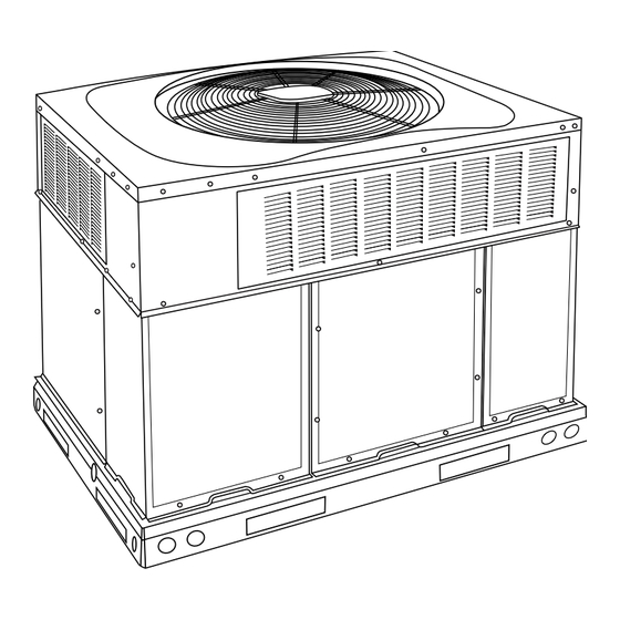
Fig. 1 - Unit 705C
Safety Considerations
This unit is equipped with electrically powered safety measures. For the
safety measures to be effective, the unit must be electrically powered at
all times after installation, other than when servicing.
WARNING
!
PERSONAL INJURY AND PROPERTY DAMAGE
HAZARD
Continuous fan mode required for proper functioning. Installation must
meet the Required Minimum Dissipation Airflow as outlined in the
Leak Dissipation System section. Follow instructions in the Continuous
Fan Speed Set-Up section to change speeds.
Improper installation adjustment, alteration, service, maintenance, or use
can cause explosion, fire, electrical shock, or other conditions which
Installation Instructions
A09033
may cause death, personal injury, or property damage. Consult a
qualified installer, service agency, or your distributor or branch for
information or assistance. The qualified installer or agency must use
factory-authorized kits or accessories when modifying this product Refer
to the individual instructions packaged with the kits or accessories when
installing.
WARNING
!
PERSONAL INJURY AND PROPERTY DAMAGE
HAZARD
For continued performance, reliability, and safety, the only approved
accessories and replacement parts are those specified by the equipment
manufacturer. The use of non-manufacturer approved parts and
accessories could invalidate the equipment limited warranty and result
in fire risk, equipment malfunction, and failure. Please review
manufacturer's instructions and replacement part catalogs available
from your equipment supplier.
Auxiliary devices which may be a POTENTIAL IGNITION SOURCE
shall not be installed in the duct work. Examples of such POTENTIAL
IGNITION SOURCES are hot surfaces with a temperature exceeding
1292°F (700°C) and electric switching devices.
Electrostatic air purifiers installed in the ductwork are permitted, if the
purifier has an airflow sensor.
False ceilings or drop ceilings must not be used as a return air
duct/plenum.
This self-contained unit is already charged with refrigerant for optimum
performance, and shouldn't require any adjustments. Should any
installation/service work on the A2L refrigerant system be needed,
non-sparking tools are required. If the refrigerant system is opened, a
refrigerant detector should be used to check for leaks. Open flames or
other ignition sources should not be present, except during brazing.
Brazing should only take place on refrigerant tubes that are open to the
atmosphere or have been properly evacuated.
Follow all safety codes. Wear safety glasses, protective clothing, and
work gloves. Use quenching cloth for brazing operations. Have a fire
extinguisher available. Read these instructions thoroughly and follow all
warnings or cautions included in literature and attached to the unit.
Consult local building codes, the current editions of the National
Electrical Code (NEC) NFPA 70.
In Canada refer to the current editions of the Canadian electrical Code
CSA C22.1.
Recognize safety information. This is the safety-alert symbol
you see this symbol on the unit and in instructions or manuals, be alert to
the potential for personal injury. Understand these signal words;
DANGER, WARNING, and CAUTION. These words are used with the
safety-alert symbol. DANGER identifies the most serious hazards which
will result in severe personal injury or death. WARNING signifies
hazards which could result in personal injury or death. CAUTION is
. When
Advertisement
Table of Contents

Related Manuals for Carrier bryant Legacy 705C


Summary of Contents for Carrier bryant Legacy 705C
-
Page 1: Table Of Contents
705C--B Legacy™13.4 SEER2 Single-Packaged Air Conditioner System with Puron Advance™ (R-454B) Refrigerant Single Phase 2-5 Nominal Tons (Sizes 24-60) Three Phase 3-5 Nominal Tons (Sizes 36-60) Installation Instructions IMPORTANT: Effective January 1, 2015, all split system and packaged may cause death, personal injury, or property damage. Consult a air conditioners must be installed pursuant to applicable regional qualified installer, service agency, or your distributor or branch for efficiency standards issued by the Department of Energy. -
Page 2: Electrical Shock Hazard
used to identify unsafe practices which may result in minor personal NOTICE injury or product and property damage. NOTE is used to highlight suggestions which will result in enhanced installation, reliability, or operation. If the unit gasketing or insulation must be replaced, ensure the material used is compliant with the two agency requirements listed. -
Page 3: Slab Mount
705C--B: Installation Instructions 1. Accessory kit number CPADCURB001A00, (small chassis) and CAUTION accessory kit number CPADCURB002A00, (large chassis) includes roof curb adapter and gaskets for the perimeter seal and duct UNIT/STRUCTURAL DAMAGE HAZARD openings. No additional modifications to the curb are required when using this kit. - Page 4 705C--B: Installation Instructions A230470 Fig. 2 – 24-30 Unit Dimensions Manufacturer reserves the right to change, at any time, specifications and designs without notice and without obligations.
- Page 5 705C--B: Installation Instructions A230471 Fig. 3 – 36-60 Unit Dimensions Manufacturer reserves the right to change, at any time, specifications and designs without notice and without obligations.
- Page 6 705C--B: Installation Instructions SMALL/COMMON CURB SMALL SUPPLY BASE UNIT LARGE BASE RETURN UNIT UNIT PLACEMENT ON COMMON CURB SMALL OR LARGE BASE UNIT LARGE CURB A180216 UNIT CATALOG (small/common (large base) SIZE NUMBER base) IN. (mm) IN. (mm) (mm) IN. (mm) (mm) (mm) (mm)
- Page 7 705C--B: Installation Instructions CAUTION - NOTICE TO RIGGERS PRUDENCE - AVIS AUX MANIPULATEUR ACCESS PANELS MUST BE IN PLACE WHEN RIGGING. PANNEAUX D'ACCES DOIT ÊTRE EN PLACE POUR MANIPULATION. Use top skid as spreader bar. / Utiliser la palette du haut comme barre de répartition DUCTS MINIMUM HEIGHT: 36"...
-
Page 8: Rigging/Lifting Of Unit
705C--B: Installation Instructions 1. Application of the lifter to the load, and adjustment of the lifts to After the unit is placed on the roof curb or mounting pad, remove the top adapt to various sizes or kinds of loads. skid. -
Page 9: Configuring Units For Downflow (Vertical) Discharge
705C--B: Installation Instructions IMPORTANT: Use flexible connectors between ductwork and unit to Adequately insulate and weatherproof all ductwork located prevent transmission of vibration. Use suitable gaskets to ensure outdoors. Insulate ducts passing through unconditioned space, and weather-tight and airtight seal. When electric heat is installed, use use vapor barrier in accordance with latest issue of Sheet Metal and Air Conditioning Contractors National Association (SMACNA) fireproof canvas (or similar heat resistant material) connector between... - Page 10 705C--B: Installation Instructions CAUTION HIGH VOLTAGE POWER LEADS UNIT COMPONENT DAMAGE HAZARD POWER (SEE UNIT WIRING SUPPLY LABEL) Failure to follow this caution may result in damage to the unit being 3-PHASE SHOWN installed. 1-PHASE USES Make all electrical connections in accordance with NFPA 70 TWO POWER EQUIP GR LEADS...
- Page 11 705C--B: Installation Instructions Provide a drip loop before running wires through panel. Secure and strain relief all wires so that they do not interfere with operation of unit. If an accessory electric heater is installed, low voltage leads from heater must be connected to factory supplied control leads from Indoor Fan Board P4 connector.
-
Page 12: Transformer Protection
705C--B: Installation Instructions Table 2 – Required Operational Checks to Ensure Proper Dissipation System Function Indoor Electric/Gas Test # T-Stat Call Compressor Heat Normal Operation None Cool Heat Dissipation Activated None Cool Heat Required Minimum Dissipation Airflow The Required Minimum Dissipation Airflow is listed in Table 3, is based on refrigerant charge, and must be met or exceeded in Continuous Fan... - Page 13 705C--B: Installation Instructions Table 3 – Physical Data-Unit UNIT SIZE NOMINAL CAPACITY (ton) 2-1/2 3-1/2 SHIPPING WEIGHT lb. SHIPPING WEIGHT (kg) Scroll COMPRESSORS Quantity REFRIGERANT (R-410A) Quantity lb 5.75 6.25 6.75 8.25 Quantity (kg) REFRIGERANT METERING DEVICE Orifice MINIMUM CONDITIONED SPACE AREA (sq.
-
Page 14: Pre-Start-Up
705C--B: Installation Instructions Pre-Start-up Work procedure for service: 1. All maintenance staff and others working in the local area shall be WARNING instructed on the nature of work being performed. Any nearby confined space work shall be avoided. 2. If any hot work is to be conducted on the refrigeration system or ENVIRONMENTAL, FIRE, EXPLOSION, ELECTRICAL associated parts, a fire extinguisher shall be available on hand. - Page 15 705C--B: Installation Instructions 14. Charge unit with Puron Advance (R-454B) refrigerant, using an An accurate thermocouple- or thermistor-type thermometer, and a gauge accurate scale. Refer to unit rating plate for required charge. Do not manifold are required when using the subcooling charging method for overfill the system.
-
Page 16: Single Cooling Fan Speed Set-Up
705C--B: Installation Instructions The cooling speed is marked “LOW” on the interface fan board (IFB) HIGH (See Fig. 14). The factory-shipped settings are noted in Table 6. There are 4 additional speed tap wires available for use in either electric heating or cooling (For color coding on the indoor fan motor leads, see Table 5). -
Page 17: Continuous Fan Operation
705C--B: Installation Instructions WARNING ELECTRICAL SHOCK HAZARD Failure to follow this warning could result in personal injury or death. Disconnect electrical power to the unit and install lockout tag before changing blower speed. Continuous Fan Operation When the DEHUM feature is not used, the continuous fan speed will be the same as cooling fan speed. - Page 18 Table 6 – Dry Coil Air Delivery* - Horizontal and Downflow Discharge Sizes 24-60 ESP (in. W.C.) Unit Size Motor Speed Blue 0.07 0.08 0.08 0.09 Med-Low Pink 0.12 0.13 0.13 0.13 0.14 0.14 0.15 1080 1025 Medium** 0.21 0.22 0.23 0.23 0.24...
- Page 19 Table 6 – Dry Coil Air Delivery* - Horizontal and Downflow Discharge Sizes 24-60 (Continued) ESP (in. W.C.) Unit Size Motor Speed Blue 0.13 0.13 0.14 0.15 0.16 0.16 0.17 0.18 0.18 0.19 1201 1153 1107 1060 1012 Med-Low Pink 0.21 0.22 0.22...
- Page 20 Table 7 – Wet Coil Pressure Drop (IN. W.C.) Unit Standard CFM (SCFM) Size 1000 1100 1200 1300 1400 1500 1600 1700 1800 1900 2000 2100 2200 0.03 0.04 0.04 0.05 0.06 0.05 0.06 0.07 0.08 0.11 0.06 0.06 0.09 0.10 0.11 0.14...
- Page 21 705C--B: Installation Instructions A240129 Fig. 15 – Connection Wiring Diagram 208/230-1-60 Manufacturer reserves the right to change, at any time, specifications and designs without notice and without obligations.
- Page 22 705C--B: Installation Instructions A240130 Fig. 16 – Ladder Wiring Diagram 208/230-1-60 Manufacturer reserves the right to change, at any time, specifications and designs without notice and without obligations.
- Page 23 705C--B: Installation Instructions A240131 Fig. 17 – Connection Wiring Diagram 208/230-3-60 Manufacturer reserves the right to change, at any time, specifications and designs without notice and without obligations.
- Page 24 705C--B: Installation Instructions A240132 Fig. 18 – Ladder Wiring Diagram 208/230-3-60 Manufacturer reserves the right to change, at any time, specifications and designs without notice and without obligations.
- Page 25 705C--B: Installation Instructions A240133 Fig. 19 – Connection Wiring Diagram 460-3-60 Manufacturer reserves the right to change, at any time, specifications and designs without notice and without obligations.
- Page 26 705C--B: Installation Instructions A240134 Fig. 20 – Ladder Wiring Diagram 460-3-60 Manufacturer reserves the right to change, at any time, specifications and designs without notice and without obligations.
- Page 27 705C--B: Installation Instructions Superheat charging table is derived from optimum performance point. (95_F [35_C] outdoor ambient and (80_F [27_C] dry bulb; 67_F [19_C] wet bulb indoor condition.) Where a dash(--) appears do not attempt to check charge or charge unit under these conditions using the superheat method. (Weigh in method should be used.) A240114 A240115 Fig.
-
Page 28: Maintenance
705C--B: Installation Instructions Maintenance cooling season and twice during the heating season, or whenever the filter becomes clogged with dust and lint. To ensure continuing high performance, and to minimize the possibility Indoor Blower and Motor of premature equipment failure, periodic maintenance must be NOTE: All motors are pre-lubricated. -
Page 29: Motor Shaft
705C--B: Installation Instructions FAN GRILLE MOTOR MOTOR SHAFT A08505 MAX DISTANCE BETWEEN TOP OF FAN GRILLE AND BOTTOM OF FAN BLADE “A” Size Fig. 22 – Fan Blade Position matter from the pan. Flush the pan and drain trough with clear water. Do not splash water on the insulation, motor, wiring, or air filter(s). - Page 30 705C--B: Installation Instructions manufacturer. Other parts may result in the ignition of refrigerant in the 3. Apply ohmmeter leads across switch. You should have continuity atmosphere from a leak. Check all electrical connections for tightness. on a closed switch. Tighten all screw connections. If any smoky or burned connections are NOTE: Because these switches are attached to refrigeration system noticed, disassemble the connection, clean all the parts, restrip the wire under pressure, it is not advisable to remove this device for...
-
Page 31: Troubleshooting
Access My Learning Center with your HVACpartners credentials at Refer to unit information plate and charging chart. Some R-454B www.MLCtraining.com. Please contact us at mylearning@carrier.com refrigerant cylinders contain a dip tube to allow liquid refrigerant to flow with questions. from cylinder in upright position. For cylinders equipped with a dip tube, charge Puron Advance (R-454B) units with cylinder in upright position and a commercial metering device in manifold hose. - Page 32 705C--B: Installation Instructions Table 12 – Troubleshooting Chart SYMPTOM CAUSE REMEDY Power failure Call power company Fuse blown or circuit breaker tripped Replace fuse or reset circuit breaker Defective contactor, transformer, control relay, or Replace component high-pressure, loss-of-charge or low-pressure switch Compressor and outdoor fan will not start Insufficient line voltage Determine cause and correct...
- Page 33 705C--B: Installation Instructions Table 13 – Dissipation Board Status Code Descriptions A240111 Manufacturer reserves the right to change, at any time, specifications and designs without notice and without obligations.
- Page 34 705C--B: Installation Instructions Start-Up Checklist (Remove and Store in Job Files) I. PRELIMINARY INFORMATION MODEL NO.: ____________________________________________ SERIAL NO.: ____________________________________________ DATE: __________________________________________________ TECHNICIAN: ___________________________________________ II. PRESTART-UP (Insert check mark in box as each item is completed) ( ) VERIFY THAT ALL PACKING MATERIALS HAVE BEEN REMOVED FROM UNIT ( ) REMOVE ALL SHIPPING HOLD DOWN BOLTS AND BRACKETS PER INSTALLATION INSTRUCTIONS ( ) CHECK ALL ELECTRICAL CONNECTIONS AND TERMINALS FOR TIGHTNESS ( ) CHECK THAT INDOOR (EVAPORATOR) AIR FILTER IS CLEAN AND IN PLACE...
- Page 35 © 2024 Carrier. All rights reserved. Edition Date: 04/24 Catalog No: II705C-01 A Proud Member of the Carrier Family Replaces: New Manufacturer reserves the right to change, at any time, specifications and designs without notice and without obligations.
Need help?
Do you have a question about the bryant Legacy 705C and is the answer not in the manual?
Questions and answers