Oki B 4545 MFP Technical Document
Hide thumbs
Also See for B 4545 MFP:
- User manual (154 pages) ,
- Safety and warranty manual (37 pages) ,
- Brochure & specs (4 pages)
Table of Contents
Advertisement
Quick Links
Advertisement
Chapters
Table of Contents
Troubleshooting

Related Manuals for Oki B 4545 MFP


Summary of Contents for Oki B 4545 MFP
- Page 1 B 4545 MFP TECHNICAL DOCUMENT 061212A...
- Page 2 - 2 - CONTENTS TECHNICAL DESCRIPTION 252 672 629A INSTALLATION GUIDE 252 672 629A MAINTENANCE GUIDE 252 672 629A ILLUSTRATED PART LIST 252 668 365A PERSONNALISATION 252 711 773A PRINTER TECHNICAL DOCUMENT 252 668 597A...
-
Page 3: Table Of Contents
- 1 - TECHNICAL DESCRIPTION CONTENTS GENERAL2 RESENTATION ENERAL ESCRIPTION CHARACTERISTICS3 HYSICAL HARACTERISTICS ENERAL ECHNICAL HARACTERISTICS ENERAL HARACTERISTICS OF ONSUMABLES FONCTIONING8 ONTROL ANEL OARD CPU B OARD SUPPLY CRYSTAL RESET PRINTING LANGUAGES (DEPENDING ON MODEL)16 NTERFACES NTERNAL ONTS APER ORMAT OMPATIBILITY WITH ECOMMENDED RIVERS... -
Page 4: General2
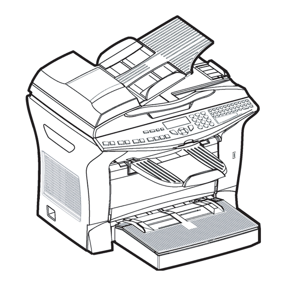
GENERAL RESENTATION Adjustable paper guide Adjustable paper guide Scroll scanner (ADF scanner) Original document output stacker Display Smart card reader Control panel Printer output stacker Printer Manual paper feed tray. On/off switch Printer paper feed tray Parallel PC port (Depending on model) USB connector LAN connector (Depending on model) -
Page 5: General Description
- 3 - ENERAL ESCRIPTION MFF terminals are part of a range of multifunction office equipment. The product consists of a duplex color scanner with a resolution of 600 dpi and a black-and-white laser printer with a resolution of 600 dpi. These two components are combined in a monobloc unit. The documents to be processed are read by means of a sheet feeder scanner using CIS (Contact Image Sensor) technology via the ADF (Automatic Document Finder) or via la the exposition window for bulky documents. -
Page 6: General Technical Characteristics
- 4 - ENERAL ECHNICAL HARACTERISTICS Equipment Dimensions (width x depth x height in mm., without 440 x 460 x 460 trays) Weight (kg) Consumables Reference Paper (RP) Type Bellegarde Turbo A4 - 80 g/m Reference Document (RD) Type ITU #1 - A4 Black/white ratio Resolution Normal mode (200 x 100 DPI) - Page 7 - 5 - Window size 220 mm x 304 mm Acquisition time for black and white document: • 600 x 200 dpiI 5,9 s • 600 x 300 dpi 8,8 s • 600 x 600 dpi 10,6 s • 600 x 1200 dpi 21,1 s •...
- Page 8 - 6 - Fax-Modem Type PSTN-G3 Maximum speed in bps (V34Fax) 33 600 V34Fax capacity in bps 33 600 à 2 400 • Incrementation in bps 2 400 V17 capacity in bps 14 400, 12 000, 9 600, 7 200 V29 capacity in bps 9 600, 7 200 V27ter capacity in bps...
-
Page 9: General Characteristics Of Consumables
- 7 - E-Mail and Fax Communication Compatibility ITU T37 Mail protocol : sending SMTP Mail protocol : polling POP3 Mail format MIME • Charset US-ASCII • Encoding 7 bits, base 64, quoted-printable SMS Communication (depending on model) Transmission Reception Mailing 10 directly 499 from address list... -
Page 10: Fonctioning8
- 8 - The displayed percentage is calculated by means of this counter, relative to the initial capacity of the consumable (from 100 % to 1 %). The values of the consumable counters are updated regularly in the EEPROM memory. At each start-up of the machine the counters are read from the EEPROM memory. -
Page 11: Cpu Board
- 9 - On this board are also installed: the external connector for the smart card and the internal connector for the loudspeaker, these latter elements being managed by the CPU. Diagram of the Connector and Sensor Locations: Loudspeaker interconnect Smart card reader List of Connectors:... - Page 12 - 10 - Block Diagram of the Electronics Architecture : Motor Control panel ADF Motor Driver P4100 P4302 Z711 Video Motor Printer FlatBed Sensor Driver P430 Z811 Printer UART P4201 CIS P4370 Z110 FlatBed Sensor adapt P4371 Z4630 P4630 ADF Sensors USB slave USB slave P4372...
-
Page 13: Usb Slave
- 11 - Diagram of the Connector Locations: slave ADF Sensor FlatBed Sensor Control panel P9461 HOST 2 ADF Motor Printer FlatBed Motor List of Connectors: Connector Location ref. Number of pins Male/female Type Printer P4201 Male straight P4370 Female Elbow, top contact Control panel... - Page 14 - 12 - Signal Input/Output RXIMP Printer status (serial data transmitted by printer) TXIMP CPU command (serial data transmitted to printer) CBSY Controller status busy SCLKIMP Serial link clock printer sync VIDEO Printer video 17-20-21 Ground 22-25 not connected linked to 10 5 V supply 5 V supply •...
- Page 15 - 13 - • ECP: Parallel Interface to PC Signal Input/Output HOSTCLK Data clock (forward) DATAECP0 Data bus LSB DATAECP1 Data bus bit 1 DATAECP2 Data bus bit 2 DATAECP3 Data bus bit 2 DATAECP4 Data bus bit 4 DATAECP5 Data bus bit 5 DATAECP6 Data bus bit 6...
- Page 16 - 14 - • USB: HOST Signal Input/Output VBUS_USB Supply from master USBN Differential pair USBP Differential pair Ground Not connected • STN: Switched Telephone Network Interface Signal Input/Output Not connected Loopback L1 Telephone line pair Telephone line pair Loopback L2 Not connected •...
-
Page 17: Supply
- 15 - SUPPLY The 24 V and 5 V supply voltages are supplied by the printer. 24 V Motor driver + 24 V Resistors R4048 // R4049 P12V 12 V regulator current generator Z4051 Resistors R4044 and R4045 5 V regulator Z113 ANAVCC vcc ana... -
Page 18: Crystal
- 16 - CRYSTAL DIGICOLOR2 12 MHz Y50 71,0524 MHz Y350 Printer 32,768 kHz Y500 Time stamp 29,4912 MHz Y550 Modem 25 MHz Y8800 6 MHz Y9400 USB H RESET Low voltage detect modem reset (I/O) Modem 3,3 V MAX809 - T : 3.08 V Z210 USB HOST DIGICOLOR2... -
Page 19: Printing Languages (Depending On Model)16
- 17 - PRINTING LANGUAGES (DEPENDING ON MODEL) PCL5e emulation: advised driver HP LasetJet 5Si PCL XL 2.1 (PCL6) emulation: advised driver: HP Laserjet 2200: Version 4.3.2.192 dated the 14/06/2002. SG Script (Adobe PS Emulation): advised driver: Adobe PS Version 1.0.6 dated the 23/05/2002 for Windows and version 8.8 for Macintosh. -
Page 20: Internal Fonts List
- 18 - NTERNAL ONTS The following list shows internal fonts as it is printed by MF products (depending on model):... - Page 21 - 19 -...
- Page 22 - 20 -...
- Page 23 - 21 -...
- Page 24 - 22 -...
- Page 25 - 23 -...
- Page 26 - 24 -...
-
Page 27: Paper Format
- 25 - APER ORMAT The following table lists the supported formats: Media Trays Media sizes Dimensions (mm) Upper Manual Lower 1 Lower 2 210 x 297 Letter 215,9 x 279,4 Legal 215,9 x 355,6 Executive 184,2 x 266,7 148 x 210 B5 (JIS) 182 x 257 Env B5 ISO... -
Page 28: Ompatibility With Ecommended Rivers
- 26 - OMPATIBILITY WITH ECOMMENDED RIVERS HP Laserjet 2200 Media sizes Media Sources Media types printer printer driver parameter (not printer driver parameter driver parameter parameter parameter PCL XL documented) parameter Automatic selection automatic tray * ordinary paper normal paper Letter manual feed upper tray... -
Page 29: Faq
- 27 - 1 - The bidirectional PJL mode is not supported 2 - Wingdings Font: The Wingdings font is not part of our internal fonts. You can download the Windgings font. If not, the Dingbats font is displayed instead. 3 - The "MISSING FONT"... - Page 30 - 1 - INSTALLATION GUIDE CONTENTS INSTALLATION REQUIREMENTS PACE EQUIREMENTS LECTRICAL EQUIREMENTS Mains Telephone line NVIRONNEMENTAL ONDITIONS UNPACKING CONNECTIONS ONNECTING THE ELEPHONE INE AND ONNECTING THE AINS UPPLY AND WITCHING ON PC ( ONNECTING THE OPTION INSTALLING PAPER SUPPLY NSTALLING THE RINTER INSTALLING THE TRAYS OCUMENT...
- Page 31 - 2 - Soft-switch 2: Scanner / Printer Configuration Soft-switch 3: Line Configuration Soft-switch 4: Fax Protocol Configuration Soft-switch 5: Voice/Loudspeaker Configuration Soft-switch 6: Line Adjustment Soft-switch 7: Reserved Soft-switch 8: Remote Readout/Internal Answering Machine / Modem Soft-switch 9: Approval + Communication Applications Soft-switch 10: Communications: Locks/Miscellaneous Soft-switch 11: Retransmissions/Logs Soft-switch 12: Reserved...
-
Page 32: Installation Requirements
- 3 - INSTALLATION REQUIREMENTS PACE EQUIREMENTS The figure above shows the overall dimensions of the machine, optional accessories not included. -
Page 33: Electrical Requirements Mains
- 4 - LECTRICAL EQUIREMENTS 1.2.1 AINS Single-phase AC supply with earth, in conformance with the information on the label on the back of your fax. Note(s) : - The machine cannot be connected to an IT type power supply. - The mains input of the machine conforms to the overvoltage safety level. -
Page 34: Connections
- 5 - CONNECTIONS ONNECTING THE ELEPHONE INE AND • Plug one end of the telephone lead (F) into socket (D) of the fax and the other end into the tele- phone wall socket. • If the machine is equipped with a LAN connection (depending on the model), plug one end of the LAN cable (supplied by your network administrator) into socket (C) of the fax and the other end into the local area network socket allocated to your terminal. -
Page 35: Installing Paper Supply
- 6 - INSTALLING PAPER SUPPLY NSTALLING THE RINTER Using the left and right notches of the printer as a guide, carefully push in the tray until it stops (as shown in the illustration). INSTALLING THE TRAYS OCUMENT OADING Install the tray by clipping the two lugs (B) in the corresponding openings (A). -
Page 36: Document Output Tray
- 7 - OCUMENT UTPUT Install the tray by clipping the two lugs of the tray (B) in the corresponding openings (A). INSTALLING ADDITIONAL PAPER TRAYS NSTALLING THE DDITIONAL APER DEPENDING ON MODEL OR OPTION Refer to the User Guide. -
Page 37: Installing The Duplex Unit
- 8 - NSTALLING THE UPLEX DEPENDING ON MODEL OR OPTION Refer to the User Guide. INSTALLING THE CONSUMABLES Refer to the User Guide. START-UP AND SOFTWARE CONFIGURATION A few seconds after switching on, as soon as the warm-up of the printer is finished, the date and the time are displayed. - Page 38 - 9 - The fax is equipped with a set of logic blocks referred to as SOS (SOft Switches) N°1 to 30. Each block consists of 8 bits called bit 1 to 8. Each bit can take a value of either 0 or 1. On the display, a block (from bit 1 to bit 8) is read from right to left.
-
Page 39: List Of Configurations (Sw) Soft-Switch 1: Ringing And Automatic Printing
- 10 - (SW) IST OF ONFIGURATIONS 8.3.1 1: R SWITCH INGING AND UTOMATIC RINTING Value Naming Reserved Reserved SOS-DURPAUSE: Long/short pause while dialing Values: # 0 (Short 2sec.) or 1 (Long 6sec.) Reserved Reserved SOS-IMPAUTO: Automatic log print Values: 0 (No) or 1 (Yes) SOS-IMPT30: Automatic printing of T30 trace after comm error. -
Page 40: Soft-Switch 5: Voice/Loudspeaker Configuration
- 11 - Value Naming SOS-DISINF: Unlimited DIS length Values: 0 (No)# 1 (Yes) SOS-LGINF: Maximum length of scan, printing, communication Values: # 0 (1 meters)1 (3 meters) SOS-ECM: Restricted ECM Values: 0 (No)# 1 (Yes) 8.3.5 5: V SWITCH OICE OUDSPEAKER ONFIGURATION... -
Page 41: Soft-Switch 9: Approval + Communication Applications
- 12 - 8.3.9 9: A SWITCH PPROVAL OMMUNICATION PPLICATIONS Value Naming Reserved Reserved Reserved SOS-REPERR: Redialing from page fault Values: 0 (No) # 1 (Yes) SOS-NOTREMIS: Printing of first page on trasmission rapport Values: 0 (No) # 1 (Yes) SOS-GRILLAGE: Burn phone numbers Values: # 0 (No) 1 (Yes) SOS-LIGNE5S: Lines of 5 sec.during reception... -
Page 42: Soft-Switch 13: Internet
- 13 - 8.3.13 S 13: I SWITCH NTERNET Value Naming SOS-BRIDEMAIL: Restricted text e-mail reception Values: # 0 (No)1 (Yes) SOS-ACKNORECNET: Send "message not received" reply on reception of corrupted mes- sages Values: 0 (No) # 1 (Yes) SOS-EFFMSGNOK: Delete corrupted messages Values: 0 (No) # 1 (Yes) SOS-PROMONET: Auto directory enrichment (Internet promotion) Values: 0 (No automatic enrichment of directory) -
Page 43: Soft-Switch 16: Internet
- 14 - 8.3.16 S 16: I SWITCH NTERNET Value Naming SOS-ACKNORECNET2: Send a "message not understood" reply on reception of TIFF att- chment Values: # 0 (Send message) 1 (Do not send message) SOS-MAILSWIMP: Printout when rerouting mailswitch Values: # 0 (Printout) 1 (No printout) Reserved Reserved SOS-ACTREEM: Enable/disable rerouting... -
Page 44: Soft-Switch 19: Miscellaneous Software Functions
- 15 - 8.3.19 S 19: M SWITCH ISCELLANEOUS OFTWARE UNCTIONS Value Naming Reserved Reserved SOS-GROUPE: Restriction on groups (or distribution list) Values: # 0 (No groups)1 (Groups accepted) SOS-REGULREC: T30 reception control inhibited Values: # 0 (No) 1 (Yes) Reserved SOS-MENUCLAVIER: Hide keyboard menus and force QWERTY keyboard Values: 0 (Shows) # 1 (Hide) -
Page 45: Soft-Switch 23: Miscellaneous
- 16 - 8.3.23 S 23: M SWITCH ISCELLANEOUS Value Naming SOS-JBIG: SUPER G3 capability to execute communication with JBIG encoding Values: 0 (No SUPER G3) 1 (negociated SUPER G3) SOS-BRID-LAN: Restriction on LAN function Values: # 0 (No)1 (Yes) SOS-FSI-NOCOVER: Inhibition of generation of cover pages Values: # 0 (FSI V6 cover page) 1 (FSI V7 cover page) SAGEM Only... -
Page 46: Soft-Switch 26: Miscellaneous
- 17 - Value Naming SOS-TXADTERMINAL: Transmit the terminal address in the server number # 0: No 1: Yes SOS-RXADTERMINAL: Receive the terminal address in the server number # 0: No 1: Yes SOS-EXPBITPDF: Export the attached file format field (Image/PDF) when exporting the directory via e-mail. -
Page 47: Soft-Switch 28: Miscellaneous
- 18 - 8.3.28 S 28: M SWITCH ISCELLANEOUS Value Naming Activation of fax modification for DTS label #0: Missing 1: Present Carrier drop in ECP mode for DTS label #0: Missing 1: Présent Disable the 1 second timer before the hanging up #0: Enabled 1: Disabled SMS reception error in manual mode in Austria... -
Page 48: Software Download
- 19 - OFTWARE OWNLOAD Three methods can be used to update the machine software: • by means of a link to a PC, • by means of an STN (switched telephone network) connection, • by means of a local network. The main software (that runs on the CPU board), the boot software, the line 2 modem software and the PCL/SG Script font files can be downloaded independently. -
Page 49: Downloading With The Miniboot
- 20 - - Enter the phone number of the fax to be downloaded in the first destinataire (addressee) field; - Click on <Emettre> (send): the transmission is effected when it reaches the top of the transmission queue. • The Quadrige calls the fax. If the connection is made, the fax displays Téléchargement en cours (download in progress) and the comm. -
Page 50: Remote Readout
- 21 - • Perform the downloading process following the steps bellow: - Modify the terminal IP adress following the steps bellow: - Go to the menu: , 2, 5, 3, 2 then OK. - Type 169 254 000 001 then OK and STOP. - Position the SOS Softswitch bit 8 at 1: , *, #, OK, 1, OK, STOP. -
Page 51: Inital Consumables
- 22 - • The “threshold” criterion is based on the page thresholds entered in the remote readout menu accessed by means of the key sequence MENU, *, 6. When a consumables counter drops below the corresponding threshold, the remote readout is triggered. For instance, if the toner threshold is set to 1500 pages, a remote readout will be transmitted when the toner counter drops below 1500, or in other words, when the remaining toner allows no more than 1500 pages to be prin- ted. - Page 52 - 23 - Field Type Char. / Num. Manual entry 0x11 char[15] TSOCIETE 0x12 char[30] TADRESSEL1 0x13 char[30] TADRESSEL2 0x14 char[30] TADRESSEL3 TCODEPOSTAL 0x15 char[15] 0x16 char[30] TVILLE 0x17 char[15] TPAYS 0x18 char[15] TLANGUE 0x19 char[30] TTELEPHONE 0x21 char* TDATE_EMIS 0x40 long T_CPT_PAGES...
-
Page 53: Remote Readout Report
- 24 - 9.4.2 EMOTE EADOUT EPORT For each transmission a remote readout report is printed. It contains all the data that have been transmit- ted to the server in transparent mode. In the case of a transmission in fax mode, the fax that is received is identical to this report. -
Page 54: Description Of The Parameters
- 25 - 9.4.3 ESCRIPTION OF THE ARAMETERS The different fields shown in the report are described below. General Information • No 23 millions (TNO_23MIL): the 23M of the module managed by the server, entered by the installer; • No de série (TNO_SERIE): the identification of the terminal, entered by the installer; •... -
Page 55: Reminders
- 26 - • Précédente télérelève le… (T_DATE_SEUIL_NOIR): date of the last remote readout triggered by the toner threshold criterion, or installation date if there has not been any previous remote readout; • (XXXX pages) (T_CPT_NOIR): theoretical number of pages remaining to be printed at the ins- tant of the triggering of the previous remote readout by the toner threshold criterion (or 0 if there has not been any previous remote readout);... -
Page 56: 10. Saving Data On Eeprom Card
- 27 - If this transmission is not possible for any reason, print out the Remote Readout parameters or display the copy counter and note these values on the intervention report. 10. SAVING DATA ON EEPROM CARD The control panel is equipped with a reader that can read and write on EEPROM cards in I2C format (“directory card”). -
Page 57: 11. Packing And Transport Of The Machine
- 28 - - Time period of connection to the Internet - Fixed times for Internet access - Prohibited time period for periodic connection - Internet connection/transmission modes - Internet rerouting mode - LAN configuration mode (manual/automatic) - Internet provider connection/mail service/servers/authentification parameters des providers internet - LAN mail service/server/authentification parameters. - Page 58 - 1 - MAINTENANCE GUIDE CONTENTS SCANNER AND COMMUNICATION REVENTIVE AINTENANCE Paper Transport Rollers Paper Separator Module CIS and Flatbed Windows Control Panel Keys and Covers CANNING AND OMMUNICATION RROR ODES General Codes Internet codes HECKS DJUSTMENTS Supply Voltages: Connections Between Power Supply Board and CPU Board Adjustment of Scanner Chassis Video Check ISASSEMBLY...
-
Page 59: Scanner And Communication
- 2 - SCANNER AND COMMUNICATION REVENTIVE AINTENANCE To maintain the fax in good working order, it is recommended to periodically perform the following operations: • Cleaning the paper transport rollers (document feeder, idler rollers). • Cleaning the paper separator. •... -
Page 60: Cis And Flatbed Windows
- 3 - 1.1.3 LATBED INDOWS • Set the on/off switch to “O” (off). • Open the flatbed scanner cover. • Wipe the scanner window with a lint-free cloth moistened with isopropyl alcohol, or with antistatic paper tissues as used for cleaning optical glass. Recommended interval: to be defined depending on utilization. - Page 61 - 4 - Code 05 - Scanning fault An incident has occurred at the location of the document to be transmitted. For example, the sheet is jammed. Code 06 - Printer not available An incident has occurred on the printer: out of paper, paper jam or cover open. In the case of a recep- tion, this incident code only appears if the “reception without paper”...
-
Page 62: Internet Codes
- 5 - Code 19 - Stopped by correspondent Communication stopped by your correspondent (for example, a fax attempts to recover a document from your fax, while there is no document waiting for this correspondent). Code 1A - Disconnect Transmission has not started: the phone line is too noisy. Code 1B - Document transmission fault In the case of a transmission: restart the transmission. -
Page 63: Checks - Adjustments
- 6 - HECKS DJUSTMENTS 1.3.1 CPU B UPPLY OLTAGES ONNECTIONS ETWEEN OWER UPPLY OARD AND OARD CPU board pin Value Function + 5 V 5 V supply 1-3-6-7-8 Ground + 24 V 24 V supply Note(s) : • The mains input of the supply is protected by a fuse. 1.3.2 DJUSTMENT OF CANNER... - Page 64 - 7 - • D7=Supply (Depending on model or option) - Fan • D8=ADF module unit • D9=Scanner-scanner support chassis-Printer unit disassembly 1.4.3 LOCK IAGRAM OF ORKSHHEETS Trays (Worksheet D1) Covers White Roller Window Control Panel (Worksheet D2) (Worksheet D3) (Worksheet D4) (Worksheet D5) Sanner Unit...
- Page 65 - 8 - SUBJECT:S CANNER UTPUT Tools • None Preliminary Steps • None. Disassembly Note(s) : To install the other trays, refer to User Guide. • Open the flatbed scanner cover. • Unstick the white panel located inside the flatbed scanner cover. •...
- Page 66 - 9 - SUBJECT:ADF, S RINTER AND APER OVERS Tools • Phillips screwdriver. • Flat screwdriver. Preliminary Steps • None. Disassembly • ADF Cover - Stand at the left-hand side of the terminal. - Open the ADF cover. - Move the arms A and B away from each other in the direction of the arrows shown on the illustration bellow, and pull the cover backward at the same time.
- Page 67 - 10 - SUBJECT:C OVERS • Printer Covers - Remove the printer covers mounting screws and pull out the covers. Mounting screw of the left- Mounting screw of the right- hand side printer cover hand side printer cover • Paper Jam - Remove the two mounting screws of the paper access cover.
- Page 68 - 11 - SUBJECT:W HITE OLLER Tools • Flat screwdriver. Preliminary Steps • None. Disassembly • Stand in front of the terminal. • Open the flatbed scanner cover. White roller • Apply a simultaneously downward and outward pressure on the bearing (A), use a flat screwdriver if necessary.
- Page 69 - 12 - SUBJECT:CIS W - CIS + CIS INDOW OTOR CORD - FB S ENSOR Tools • Phillips screwdriver. Preliminary Steps • Disassembly the right-hand side cover (Worksheet D2). Disassembly • Stand at the front of the terminal. • Open the flatbed scanner cover. •...
- Page 70 - 13 - SUBJECT:CIS W - CIS + CIS INDOW OTOR CORD CORD - FB SENSOR • Belt - Compress the belt spring and lock its arm as shown on the illustration bellow.. Dead stop of the spring arm Motor wheel - Remove the motor wheel using a screwdriver and free the belt.
- Page 71 - 14 - SUBJECT:CIS W - CIS + CIS - FB S INDOW OTOR CORD Attention - Memorize the cable path for re-assembly. - Remove the FB sensor from its housing and disconnect the lead. • CIS - Disconnect the CIS cord and disassemble the CIS + support unit. - Separate the CIS from its support.
- Page 72 - 15 - SUBJECT:E QUIPPED ONTROL ANEL OUDSPEAKERS Tools • None. Preliminary Steps • None. Disassembly • Stand at the front of the terminal. • Gently lift the front part of the control panel until it comes out. • Disconnect the PCU card CIS cord and the loudspeaker connector. •...
- Page 73 - 16 - SUBJECT:E QUIPPED ONTROL ANEL OUDSPEAKERS • Position the loudspeaker in its housing as shown on the illustration bellow • Position the upper part of the control panel on the chassis. • Connect the loudspeaker and control panel connectors. •...
- Page 74 - 17 - SUBJECT:CPU M ODULE Tools • Phillips screwdriver. Preliminary Steps • Disassemble the right-hand side cover. (worksheet D2). Disassembly • Disconnect the leads and the CIS cords coming on the CPU module connectors. • Remove the CPU module mounting screw located at the front of the terminal. CPU module mounting screw •...
- Page 75 - 18 - SUBJECT:S ) - F UPPLY DEPENDING ON MODEL OR OPTION Tools • Phillips screwdriver. Preliminary Steps • Disassemble the left cover (Worksheet D2). Disassembly • Disconnect the supply and fan leads connector • Remove the fan from its housing. •...
- Page 76 - 19 - SUBJECT:ADF M ODULE Tools • Phillips screwdriver. Preliminary steps • Disassemble the ADF cover (worksheet D2). Disassembly • Disassemble the motor cover • ADF Feeder - Unlock the two feeder bearings (1) and remove the feeder. Feeder Motor connector Motor...
- Page 77 - 20 - SUBJECT:ADF U Assembly • Unpack and visually inspect the new parts. • Position the motor using the guides. • Attach the motor with the two screws, do not forget to put the ground braid between the screw and the motor support.
- Page 78 - 21 - SUBJECT:S CANNER RINTER NTERFACE RINTER UNIT ISASSEMBLY Tools • Phillips screwdriver. Preliminary Steps • Disassemble side covers, printer covers and paper access cover (worksheet D2). Disassembly • Disconnect all wires coming from the scanner unit, and free them from their cable guide. •...
- Page 79 - 22 - SUBJECT:S CANNER RINTER INTERFACE RINTER UNIT ISASSEMBLY • Put the scanner module on the interface, push it to the right-hand side until the clip locks (see illustration bellow). • Insert the control panel (see worksheet D5). • Arrange the cables as shown on the illustrations bellow. •...
-
Page 80: Initializing And Erasing The Memories
- 23 - UNCTIONS OF THE DMINISTRATOR 1.5.1 NITIALIZING AND RASING THE EMORIES First set the installation parameter C bit 8 to 1. ONFIGURATION • Reset to default configuration (factory configuration) of all parameters (user and installer (or technical)): MENU •... - Page 81 - 24 - • Printout of all parameters (including installation and technical parameters): MENU • Switch to forced standby mode, independently of the clock: MENU • Switch to “software download by phone” mode: MENU • Switch to “software download by PC link” mode: MENU •...
-
Page 82: Replacing The Cpu Board
- 25 - • Display LAN rate : MENU • Manually reboot the machine (with SOS 1 bit 8 set to 1): MENU • Accept soft download via Internet or Intranet (with SOS 1 bit 8 set to 1): MENU •... -
Page 83: Laser Printer
- 26 - LASER PRINTER ERIODIC AINTENANCE Refer to the laser printer Technical Description ref. 251 593 296 RROR ESSAGES AND ORRECTIVE EASURES Refer to the laser printer Technical Description ref. 251 593 296 EPAIR Refer to the laser printer Technical Description ref. 251 593 296 ISASSEMBLY SSEMBLY ORKSHEETS... -
Page 84: Illustrated Part List
- 1 - NOMENCLATURE ILLUSTREE ILLUSTRATED PART LIST USING THE PART LIST TABLES ABLE COLUMNS PARE PARTS ORDERING 1 / F IGURE Ensemble MFF et réceptacles MFF Assembly and trays 2 / F IGURE Ensemble pupitre-chassis scanner et imprimante Control panel - scanner chassis assembly and printer 3 / F IGURE Capot supérieur... - Page 85 - 2 - 11 / F IGURE Transport papier Paper take-up section 12 / F IGURE Four Fuser unit 13 / F IGURE Cartes et tête d’impression Cards and print head 14/ F IGURE Alimentation duplexeur Power supply duplex...
-
Page 86: Using The Part List Tables
- 4 - USING THE PART LIST TABLES ABLE COLUMNS • ITEM NUMBER column: number of the item illustrated on the corresponding figure. Note 1: An item number preceded by a hyphen "-" is a non-illustrated item. Note 2: An item may be illustrated in a figure without being listed in the corresponding part list: such an article cannot be replaced other than by replacing the subassembly of which it is part. - Page 87 - 5 - 1 / F LANCHE IGURE...
-
Page 88: P Age 1 / Figure
- 6 - ITEM No. REFERENCE DESIGNATION MFFV2 de base 252440808 Basic MFFV2 unit Introducteur scanner assemblé 50233001 Document loading tray Voir § 3 Cordon d’alimentation secteur See § 3 AC Power cord Voir § 3 Cordon ligne téléphonique See § 3 Telephone line cord Bac papier imprimante 150233501... -
Page 89: P Age 2 / Figure
- 7 - 2 / F IGURE... -
Page 90: Ensemble Pupitre-Chassis Scanner Et Imprimante
- 8 - ITEM No. REFERENCE DESIGNATION Voir § 3 Pupitre équipéPanel equiped B4545 MFP S50138801 Scanner assemblé 251285555 Scanner assembly Module recto/verso (selon modèle ou option) 189184846 Duplex unit (option) Capot droit coloré 252432541 Right cover colored Bac supplémentaire 500 feuilles (selon modèle ou 252565569 option) SCPU (option) -
Page 91: P Age 3 / Figure
- 9 - 3 / F IGURE... -
Page 92: Capot Supérieur
- 10 - ITEM No. REFERENCE DESIGNATION Capot ADF assemblé 253088601 ADF Cover assembly Capot moteur 253088701 Motor cover Module ADF 250233201 ADF assembly Capot scanner 253088501 Flap assembly Butée du réceptacle scanner 250937201 Scanner output tray adjuster Poignée assemblée 251902901 Handle assembly Vis RLX 3-10 AC.ZN Blanc P. -
Page 93: P Age 4 / Figure
- 11 - 4 / F IGURE... -
Page 94: Module Adf Adf Assembly
- 12 - ITEM No. REFERENCE DESIGNATION Chargeur ADF 251269709 Feeder assembly Bloc papier ADF assemblé 250233301 ADF paper way assembly Pignon 19 dents large 251473957 19 teeth gear Lame de masse 251283936 Ground plate Pignon 22/18 dents 251474011 22/18 teeth gear Vis de fixation du moteur 186918224 3-10 Self-trapping screw for plastic... -
Page 95: P Age 5 / Figure
- 13 - 5 / F IGURE... -
Page 96: Ensemble Support Cis Et Motorisation
- 14 - ITEM No. REFERENCE DESIGNATION Coque supérieure assemblée 251284222 Upper cover assembly Coque inférieure assemblée 251284412 Lower cover assembly Ensemble support cis et motorisation CIS support and motor drive assemblies IGURE... -
Page 97: P Age 6 / Figure
- 15 - 6 / F IGURE... -
Page 98: Ensemble Capot Inférieur
- 16 - ITEM No. REFERENCE DESIGNATION Ensemble support CIS 250518701 CIS support assembly Patins 250610101 CIS stopper Axe guide 251284467 Guide shaft Poulie tendeur 251474389 Belt weel Ressort tendeur 251474371 Belt spring Rondelle poulie 251287603 Belt weel washer Courroie 188238330 Belt Nappe... -
Page 99: P Age 7 / Figure
- 17 - 7 / F IGURE... -
Page 100: Cis
- 18 - ITEM No. REFERENCE DESIGNATION 150138701 Ressort 251295473 CIS spring Support CIS 251474392 CIS support Ferrite 187956942 CIS ferrite core IGURE... -
Page 101: P Age 8 / Figure
- 19 - 8 / F IGURE... -
Page 102: Imprimante Assemblée
- 20 - ITEM No. REFERENCE DESIGNATION Imprimante 189139276 Printer Haut parleur équipé 257001801 Speaker assembly Interface colorée 251474516 Interface colored Capot accès papier 253088801 Paper access cover Mylar carte UC 250813501 Mylar UC board Voir § 3 Carte UC S55093701 UC board Tôle UC MFFV2... -
Page 103: P Age 9 / Figure
- 21 - 9 / F IGURE... -
Page 104: Tiroir
- 22 - ITEM No. REFERENCE DESIGNATION Tiroir papier 150233501 Tray assembly Couvercle 188480710 Cover Tiroir Tray IGURE... -
Page 105: P Age 10 / Figure
- 23 - 10 / F IGURE... -
Page 106: Prise Papier Paper Charger
- 24 - ITEM No. REFERENCE DESIGNATION 153359601 Structure gauche assemblée Left frame assy 1565522401 Ventilateur Fan unit 188478806 Moteur Motor 251616891 Support assemblé Hollder assembly 251616883 Platine assemblée Holder assembly 151031701 Guide papier assemblé Regulation plate assembly 153358501 Structure droite assemblée Right frame assembly Prise papier 10 /... - Page 107 - 25 - Page 11 / FIGURE 11...
- Page 108 - 26 - ITEM No. REFERENCE DESIGNATION Unité de transfert 150233601 Transfert unit Avance papier assemblée 150233701 Paper take-up assembly Galet 153358601 Roller Embrayage 2551402301 Clutch Ressort pour palette imprimante 150936801 Pressure spring Palette imprimante 150235901 Tray Capteur 156215601 Switch Support 150710801 Holder...
- Page 109 - 27 - Page 12 / FIGURE 12...
- Page 110 - 28 - ITEM No. REFERENCE DESIGNATION FGuide assembly 151031601 Fuser unit - Higher part Four - Partie supérieure 150233401 Fuser unit - Lower part Four 12 / Fuser unit IGURE...
- Page 111 - 29 - Page 13 / FIGURE 13...
- Page 112 - 30 - ITEM No. REFERENCE DESIGNATION Carte alimentation 156420001 Power supply Carte HT 155093801 HT Card Tête d’impression assemblé 150138601 Print head assembly Cartes et tête d’impression 13 / Boards and print head IGURE...
- Page 113 - 31 - Page 14 / FIGURE 14...
- Page 114 - 32 - ITEM No. REFERENCE DESIGNATION Bloc d’alimentaion du duplexeur 156419901 Power supply of duplex Alimentation duplexeur 14 / Power supply duplex IGURE...
- Page 115 - 2 -...
- Page 116 PRINTER SERVICE MANUAL TECHNICAL DOCUMENT...
-
Page 117: Safety Precautions For Inspection And Service
SAFETY PRECAUTIONS FOR INSPECTION AND SERVICE • When performing inspection and service procedures, observe the following precautions to prevent accidents and ensure utmost safety. ✽ Depending on the model, some of the precautions given in the following do not apply. •... - Page 118 WARNING 2. Before starting the procedures, be sure to unplug the power cord. • This product contains a high-voltage unit and a circuit with a large current capacity that may cause an electric shock or burn. • The product also contains parts that can jerk suddenly and cause injury. •...
- Page 119 WARNING 8. Do not touch a high-temperature part. • A part marked with the symbol shown on the left and other parts such as the exposure lamp and fusing roller can be very hot while the machine is ener- gized. Touching them may result in a burn. •...
- Page 120 CAUTION 2. Precautions for Servicing with Covers and Parts Removed. • Wherever feasible, keep all parts and covers mounted when energizing the product. • If energizing the product with a cover removed is absolutely unavoidable, do not touch any exposed live parts and use care not to allow your clothing to be caught in the moving parts.
-
Page 121: Used Batteries Precautions
1-3. Used Batteries Precautions ALL Areas CAUTION Danger of explosion if battery is incorrectly replaced. Replace only with the same or equivalent type recommended by the manufacturer. Dispose of used batteries according to the manufacturer’s instructions. Germany VORSICHT! Explosionsgefahr bei unsachgemäßem Austausch der Batterie. Ersatz nur durch denselben oder einen vom Hersteller empfohlenen gleichwertigen Typ. -
Page 122: Other Precautions
1-4. Other Precautions • When handling circuit boards, observe the “HANDLING of PWBs”. • The PC Drum is a very delicate component. Observe the precautions given in “HAN- DLING OF THE PC DRUM” because mishandling may result in serious image problems. •... - Page 123 4. Precautions for Dis/Reassembly • Be sure to unplug the copier from the outlet before attempting to service the copier. • The basic rule is not to operate the copier anytime during disassembly. If it is absolutely necessary to run the copier with its covers removed, use care not to allow your clothing to be caught in revolving parts such as the timing belt and gears.
- Page 124 8. Handling of the PC Drum ✽ Only for Products Not Employing an Imaging Cartridge. During Transportation/Storage • Use the specified carton whenever moving or storing the PC Drum. • The storage temperature is in the range between –20°C and +40°C. •...
- Page 125 C. Soak a small amount of either ethyl alcohol or iso- propyl alcohol into a clean, unused Dust-Free Cot- ton Pad which has been folded over into quarters. Now, wipe the surface of the PC Drum in one con- tinuous movement from its rear edge to its front edge and off its surface one to two times.
-
Page 126: Safety Information
1-6. Safety information Laser Safety • This is a digital machine certified as a class 1 laser product. There is no possibility of danger from a laser, provided the machine is serviced according to the instruction in this manual. Internal Laser Radiation semiconductor laser Maximum power of the laser diode 15 mW... - Page 127 the U.S.A., Canada (CDRH Regulation) • This machine is certified as a Class I Laser product under Radiation Performance Stan- dard according to the Food, Drug and Cosmetic Act of 1990. Compliance is mandatory for Laser products marketed in the United States and is reported to the Center for Devices and Radiological Health (CDRH) of the U.S.
- Page 128 P-12...
-
Page 129: Laser Safety Label
1-7. Laser Safety Label • A laser safety label is attached to the machine as shown below. 4136S505AB 1-8. Laser Caution Label • A laser caution label is attached to the inside of the machine as shown below. 4136S001AA P-13... -
Page 130: Precautions For Handling The Laser Equipment
1-9. PRECAUTIONS FOR HANDLING THE LASER EQUIPMENT • When laser protective goggles are to be used, select ones with a lens conforming to the above specifications. • When a disassembly job needs to be performed in the laser beam path, such as when working around the printerhead and PC Drum, be sure first to turn the printer OFF. -
Page 131: General Troubleshooting
INDEX GENERAL TROUBLESHOOTING MECHANICAL/ELECTRICAL MAINTENANCE DIS/REASSEMBLY, ADJUSTMENT... - Page 132 CONTENTS 1. Safety Precautions for Inspection and Service ..........11 1-1. Warning ....................11 1-2. Caution .....................13 1-3. Used Batteries Precautions ..............15 1-4. Other Precautions ..................16 1-5. Precautions for Service ................16 1-6. Safety information ..................110 (1) Laser Safety ..................110 (2) Internal Laser Radiation ..............110 1-7.
- Page 133 7-1. Overview ....................M-11 7-2. PC Drum ....................M-13 7-3. Developing System ..................M-14 7-4. Detection of Toner Cartridge ..............M-15 (1) Installation detection ................M-15 (2) Detection of a new Toner Cartridge ..........M-15 (3) Toner near empty and empty detection ...........M-15 8. IMAGE TRANSFER ..................M-16 8-1.
- Page 134 1-2. Removal of Units ..................D-4 (1) Removal of the PH Unit ..............D-4 1-3. Disassembly of the Engine ...............D-5 (1) Removal of the Main Motor ..............D-5 (2) Removal of the Paper Empty Sensor ..........D-5 (3) Removal of the Paper Take-Up Solenoid ........D-6 (4) Removal of the Paper Take-Up Clutch Gear ........D-7 (5) Removal of the Torque Limiter ............D-8 (6) Disassembly of the Fusing Unit ............D-9...
-
Page 135: General
GENERAL... -
Page 136: Specifications
SPECIFICATIONS Printer Type Desktop Laser Beam Printer Exposure System Laser diode + Polygon Mirror Resolution 600 dpi (1200 dpi in half-speed mode) Copy Paper Size A4, A5, B5 8.5 × 14, 8.5 × 11, 3 × 5, 5.5 × 8.5, 7 1/4 × 10 1/2 Media Type Plain paper (60 to 90 g/m Recycled paper (60 to 90 g/m... - Page 137 Controller (GDI) Control Panel LED × 1, SW × 1 ASIC N1-Chips (Naltec Original ASIC) Memory Configuration Standard ROM: 64 KB (in ASIC) EEPROM: 1 Kilobit Flash ROM: 2 Megabits (250 KB) RAM: 8 MB (64-Megabit SDRAM: 64 Megabits × 1) Interface IEEE1284 Parallel (Compatible/Nibble/ECP) USB 1.1...
-
Page 138: Precautions For Installation
PRECAUTIONS FOR INSTALLATION 2-1. Installation Site To ensure utmost safety and avoid breakdown, the printer should NOT be used in a place: • Where it will be subjected to extremely high or low temperature or humidity. • Where it will be subjected to sudden fluctuations in either temperature or humidity. •... -
Page 139: Precautions For Use
PRECAUTIONS FOR USE 3-1. To Ensure the Printer is Used in an Optimum Condition • Never place a heavy object on the printer or subject the printer to shocks. • Insert the power plug all the way into the outlet. •... -
Page 140: Handling Of The Consumables
HANDLING OF THE CONSUMABLES Before using any consumables, always read the label on its container carefully. • Paper can easily damp. To prevent absorption of moisture, store paper in a place with lit- tle moisture. • Keep consumables out of the reach of children. •... -
Page 141: Mechanical/ Electrical
MECHANICAL/ ELECTRICAL... -
Page 142: Components Layout
COMPONENTS LAYOUT 4136M534AA 1. Print Head (PH) Unit 5. Multipurpose (MP) Tray 2. Exit Roller 6. Toner Cartridge 3. Fusing Unit 7. Drum Cartridge 4. Image Transfer Section... -
Page 143: Paper Path
PAPER PATH Exit Tray Multipurpose Tray 4136M539AA • The printer adopts the 1-way paper feeding system by means of the Multipurpose Tray (capable of holding up to 150 sheets of paper). • The paper taken up and fed in by the Paper Take-Up Roll is transported through the printer by the Image Transfer Roller, Fusing Roller, and Exit Roller and fed out of the printer face down onto the Exit Tray. -
Page 144: Electrical Components Layout
ELECTRICAL COMPONENTS LAYOUT 3-1. Printer PWB-P 4136M001AB Main Motor Front Door Switch Cooling Fan Motor Multipurpose Tray Paper Empty Sensor Fusing Roller Heater Lamp Exit Sensor Thermistor SL-1 Paper Take-Up Solenoid Thermostat PU-1 Power Unit Print Head Unit HV-1 High Voltage Unit Paper Take-Up Switch PWB-P Controller/Mechanical Control Board... -
Page 145: Operating Sequence
OPERATING SEQUENCE 4-1. Print Start Sequence /PRINT Polygon Motor Main Motor Paper Take-Up Solenoid Drum Charge Drum charge DC Drum charge DC Output Exposure Output Charge Charge Developing Output Reverse bias Reverse bias Image Unexposed area output Transfer Negative output Negative output Output 4-2. -
Page 146: Print Head (Ph
PRINT HEAD (PH) 5-1. Construction • The laser beam light emitted from the Print Head is used to scan the image as driven by the Polygon Motor. SOS Sensor G1 Lens Semiconductor Laser G2 Lens 1st Mirror 2nd Mirror SOS Mirror Polygon Mirror 4136M005AA... -
Page 147: Laser Exposure Process
5-2. Laser Exposure Process • The laser beam light emitted from the Print Head is used to create an electrostatic latent image on the surface of the PC Drum. • The following control is provided to correctly time image printing. Print Head Unit Laser Diode Polygon Motor... -
Page 148: Laser Emission Timing
5-3. Laser Emission Timing • When a READY signal is detected a given period of time after the print command has been issued, the Controller/Mechanical Control Board outputs a laser ON signal. • The laser ON signal makes a laser beam to be emitted and the laser beam travels to the Polygon Mirror, G1 Lens, and the SOS Mirror to eventually hit the SOS Sensor, which generates an SOS signal. -
Page 149: Laser Emission Area
5-4. Laser Emission Area Main scanning direction • The print start position is determined by the main scanning print start signal (/HSYNC) output from the Controller/Mechanical Control Board and the width of the paper. • The laser emission area is determined by the paper size. Areas with a width of 4 mm on both edges are not, however, printed. -
Page 150: Cooling Of The Printer Interior
5-5. Cooling of the Printer Interior • The Cooling Fan Motor is used to discharge heat generated from the PH Unit out of the printer, thereby preventing the PH Unit from getting hot. PH Unit Cooling Fan Motor 4136M518AA... -
Page 151: Drum Charge
DRUM CHARGE Overview • The PC Drum is charged with static electricity before laser exposure. • The Drum Charge Brush and the Pre-charge Film are used for charging. • Since the Drum Charge Brush and the Pre-charge Film directly deposit charge on the PC Drum, they produce little ozone. -
Page 152: Overview
IC (IMAGING CARTRIDGE) SECTION 7-1. Overview • The illustration below shows the construction of the Toner Cartridge and the Developing Unit. • This printer adopts the single-component FMT, or Fine Micro Toning, developing system. • The Toner Agitating Screw conveys toner in the Toner Cartridge onto the Toner Supply Roller. - Page 153 • The Imaging Cartridge consists of a T/C (Toner Cartridge) and a D/C (Drum Cartridge) (see the illustration below). D/C (Drum Cartridge) Imaging Cartridge 4136M511AA 4136M513AA T/C (Toner Cartridge) M-12...
-
Page 154: Pc Drum
7-2. PC Drum • The PC Drum used in this printer is the organic photoconductor (OPC) type. • The drum consists of two layers - Charge Transport Layer (CTL) and the Charge Gener- ating Layer (CGL) - applied to an aluminum alloy base (cylinder). Handling Precautions: The PC Drum of this type exhibits light fatigue after being exposed to light for a long time, which results in its sensitivity being changed. -
Page 155: Developing System
7-3. Developing System • The Toner Agitating Screw conveys toner in the Toner Cartridge onto the Toner Supply Roller. • The Toner Supply Roller transports the toner to the Sleeve Roller. • The 1st Toner Blade located above the Sleeve Roller spreads a thin, even coat of toner over the Sleeve Roller. -
Page 156: Detection Of Toner Cartridge
7-4. Detection of Toner Cartridge Installation detection • The IC chip (CSIC) built into the Toner Cartridge detects that the Imaging Cartridge is installed in position when the power switch is turned OFF and ON, and the Front Door is opened and closed. -
Page 157: Image Transfer
IMAGE TRANSFER 8-1. Overview • The toner image formed on the surface of the PC Drum during the developing process is transferred onto the paper. • This printer adopts the roller image transfer system, in which the Image Transfer Roller is used to transfer the image onto the paper. -
Page 158: Overview
FUSING UNIT 9-1. Overview • The toner image transferred onto the paper is securely fixed to the paper. • A heated roller system is used as the fusing system. The paper, to which the toner image has been transferred, is fed between the Fusing Roller heated by the Fusing Roller Heater Lamp and the Pressure Roller. -
Page 159: Fusing Unit Temperature Control
9-2. Fusing Unit Temperature Control Temperature change Thermistor-detected temperature Warm-up 205 °C Printing 185 °C (600 dpi) 160 °C Printing 155 °C (1200 dpi) Standby 130 °C Mode 1: 300 sec. Mode 2: 208 sec. Mode 3 Thermistor-Detected Temperature at Start of Temperature Control Less than 50 °C 50 °C to 130 °C More than 130 °C Power OFF... -
Page 160: Temperature Control Mode
Temperature control mode During a print cycle, the fusing temperature is regulated in accordance with the elapsed time since the completion of the warm-up cycle. • Mode 1 Mode 1 lasts for 5 min. If, however, mode 1 is interrupted in mid-operation and the ther- mistor temperature is 50 °C or more, the timer count before the interruption continues. -
Page 161: 10. Paper Take-Up Section
10. PAPER TAKE-UP SECTION 10-1. Multipurpose Tray Paper take-up mechanism • When the Paper Take-Up Solenoid is energized, drive from the Main Motor is transmitted to the Paper Take-Up Roll through the Paper Take-Up Clutch, turning the Paper Take-Up Roll. •... -
Page 162: Paper Empty Detection
Paper empty detection • There is a Multipurpose Tray Paper Empty Sensor provided on the upper portion of the Multipurpose Tray. It detects paper loaded in the tray. • When there is a paper stack loaded in the tray, the actuator is raised to block the Paper Empty Sensor. -
Page 163: 11. Paper Exit
11. PAPER EXIT 11-1. Paper Exit Mechanism • The paper exit mechanism transports the paper that has been subjected to the fusing process onto the Exit Roller. • The Exit Sensor detects not only a paper misfeed but also an open Upper Cover. Exit Tray Exit Roll Face-down Exit... -
Page 164: Maintenance
MAINTENANCE... -
Page 165: Maintenance Schedule
MAINTENANCE SCHEDULE • To ensure that the printer produces good printed pages and to extend its service life, it is recommended that the maintenance jobs described in this schedule be carried out as instructed. Replace Ref. Page in Making one PM Parts Clean This Manual... -
Page 166: Guidelines For Life Specifications Values By Unit
1-1. Guidelines for Life Specifications Values by Unit • The life specifications value represents the number of printed pages produced or figures equivalent to it when given conditions (see the Table given below) are met. It can be more or less depending on how each individual printer is used. Print Conditions Job type Making one printed page per job... -
Page 167: Replacement/Cleaning Of Parts
REPLACEMENT/CLEANING OF PARTS Cleaning of the Paper Take-Up Roll <Printer> 1. Remove the Imaging Cartridge. ☞ E-5 NOTE • The Imaging Cartridge is the Drum Cartridge, to which the Toner Cartridge is mounted. 2. Using a soft cloth, wipe the surface of the Paper Take-Up Roll clean of dirt. -
Page 168: Replacement Of The Image Transfer Roller
Replacement of the Image Transfer Roller 1. Remove the Imaging Cartridge. ☞ E-5 2. Remove the Fusing Unit. ☞ E-8 3. Place the levers of the bushings (white) on the right and left ends of the Image Transfer Roller toward this side and remove the Image Transfer Roller from the Image Transfer Roller holder. -
Page 169: Replacement Of Units
REPLACEMENT OF UNITS Replacement of the Toner Cartridge <Removal Procedures> 1. Open the Front Door. 4136E005AA 2. Remove the Imaging Cartridge. 4136E006AA 3. Pull the lever of the Toner Cartridge in the direc- tion shown in the illustration and disconnect the Toner Cartridge from the Drum Cartridge. - Page 170 <Installation Procedures> 1. Take out a new Toner Cartridge and shake it in the horizontal direction sufficiently so that toner is agitated. NOTE • Placing the Toner Cartridge in an upright position or shaking it vigorously will spill toner. 4136E008AA 2.
-
Page 171: Replacement Of The Drum Cartridge
Replacement of the Drum Cartridge <Removal Procedures> 1. Remove the Imaging Cartridge. ☞ E-5 2. Pull the lever of the Toner Cartridge in the direc- tion shown in the illustration and disconnect the Drum Cartridge. 4136E011AC <Installation Procedures> 1. Mount the Toner Cartridge to a new Drum Car- tridge. -
Page 172: Replacement Of The Fusing Unit
Replacement of the Fusing Unit <Removal Procedures> 1. Turn OFF the power switch and leave the printer to stand idle for about 20 min. 2. Remove the Left and Right Covers. 3. Remove two screws and two washers. Then, remove the Fusing Unit protective metal bracket. 4136E013AC 4. - Page 173 <Installation Procedures> 1. Take out the Fusing Unit and cushioning materials. 2. Connect connector A. 3. Mount the Fusing Unit in the printer and secure it in position by tightening the two screws. 4. Connect connectors B and C. NOTE •...
-
Page 174: Dis/Reassembly, Adjustment
DIS/REASSEMBLY, ADJUSTMENT... -
Page 175: Precautions For Disassembly/Adjustments
PRECAUTIONS FOR DISASSEMBLY/ADJUSTMENTS 1-1. Parts That Must Not be Touched Variable resistors on board Do not turn the variable resistors on boards for which no adjusting instructions are given in ADJUSTMENT. -
Page 176: Removal Of The Controller/Mechanical Control Board
Removal of the Controller/Mechanical Control Board <Removal Procedures> 1. Remove the Right Cover. 2. Remove three screws and the protective metal bracket. 4136D054AA 3. Disconnect all connectors and flat cables from the Controller/Mechanical Control Board. NOTE • Use utmost care not to snap off the flat cable. 4. -
Page 177: Removal Of The Power Unit
Removal of the Power Unit 1. Remove the Fusing Unit. ☞ E-8 2. Remove two screws and the Power Switch stay. 3. Remove the Power Switch. 4136D060AA 4. Disconnect one connector from the Controller/ Mechanical Control Board. 5. Remove six screws, disconnect three connectors, and remove the Power Unit Assy. -
Page 178: Removal Of Units
1-2. Removal of Units Removal of the PH Unit CAUTION • NEVER attempt to replace the PH Unit with power being supplied to the printer. Doing that could lead to exposure to the laser beam, resulting in blind- ness. • NEVER attempt to disassemble or adjust the PH Unit. Doing that could lead to exposure to the laser beam, resulting in blindness. -
Page 179: Disassembly Of The Engine
1-3. Disassembly of the Engine Removal of the Main Motor 1. Remove the Left Cover. 2. Disconnect one connector. 3. Remove two screws, two washers, and the Main Motor. 4136D010AA Removal of the Paper Empty Sensor 1. Remove the Front Door. 2. -
Page 180: Removal Of The Paper Take-Up Solenoid
7. Disconnect one connector and remove the Paper Empty Sensor. 4136D014AA Removal of the Paper Take-Up Solenoid 1. Remove the Left Cover. ☞ E-8 2. Disconnect one connector of the Paper Take-Up Solenoid. 4136D058AA 3. Remove one screw and the Paper Take-Up Sole- noid. -
Page 181: Removal Of The Paper Take-Up Clutch Gear
Removal of the Paper Take-Up Clutch Gear 1. Remove the Fusing Unit. ☞ E-8 2. Remove the Power Unit. ☞ D-3 3. Remove the Paper Take-Up Upper Guide Assy. ☞ D-5 4. Disconnect one connector and remove the Cool- ing Fan Motor. 5. -
Page 182: Removal Of The Torque Limiter
12. Remove one screw and the Paper Take-Up Sole- noid. 4136D018AA 13. Unhook two tabs and remove the Paper Take-Up Clutch Gear. 4136D057AA Removal of the Torque Limiter 1. Remove the Paper take up Clutch Gear. 2. Unhook three tabs and take apart the Paper Torque Limiter Take-Up Clutch Gear then, remove the Torque Coupling... -
Page 183: Disassembly Of The Fusing Unit
After setting replaced Paper Take-Up Clutch Gear (Torque Limiter) to the shaft, Rotate the Paper Take- Up Clutch Gear by hand (Need to be released Sole- noid Flapper). 4136D060AA Look at the stop position of the Take-Up Roller from Clutch Gear side. 1. - Page 184 2. Remove two screws and disconnect the Fusing Unit. 4136D021AA 3. Remove two bushings and the Pressure Roller. 4136D022AA Precautions for Installation of Bushings • Make sure that the slits in the bushing are properly aligned with the rib of the Fusing Unit. 4136D040AA 4.
- Page 185 8. Remove the four Fusing Roller Paper Separator Fingers. NOTE • Use care not to lose the springs. 4136D033AA 9. Remove one screw and the Thermistor. NOTE • When reinstalling the Thermistor, route the har- ness as shown in the illustration. 10.
-
Page 186: Troubleshooting
TROUBLESHOOTING... -
Page 187: Introduction
INTRODUCTION • This chapter contains the items required or used when troubleshooting various printer problems. 1-1. Electric Components Check Procedures • The following procedures can be used to check to see if an electric component is fully operational when a paper misfeed or a malfunction occurs in the printer. Sensors Step Check... -
Page 188: Switches
Switches Step Check Result Action Replace the switch. Does the input signal (NO) to the Controller/Mechani- Replace the Con- cal Control Board go from LOW to HIGH when the troller/Mechanical switch is actuated? Control Board. Not Use 4025T523AB Solenoids Step Check Result Action... -
Page 189: Motors
Motors Step Check Result Action Is the LOCK signal of the Controller/Mechani- Replace the Controller/ cal Control Board HIGH when the printer is in Mechanical Control Board. the standby state? Replace the motor. YES Replace the motor. Does the REM signal of the Controller/ Mechanical Control Board go from HIGH to Replace the Controller/ LOW when the motor is energized? -
Page 190: Overall Control Configuration
1-2. Overall Control Configuration • Understanding the overall control configuration will help perform the troubleshooting pro- cedures for paper misfeeds, malfunctions, and image problems. Control Panel (PWB-O) Controller/Mechanical Power Unit (PU1) PH Assy Control Board 2nd Paper Cassette Printer Drive System Duplex Unit Control System Line 4136T009CA... -
Page 191: Paper Misfeed
PAPER MISFEED 2-1. Initial Check Items • When a paper misfeed occurs in the printer, first make the following initial checks. Check Action Does the paper meet product specifications? Replace paper. Replace paper. Is the paper curled, wavy, or damp? Instruct user in correct paper storage. -
Page 192: Locations Of Misfeed Detection Sensors
2-2. Locations of Misfeed Detection Sensors • 150-sheet-capacity Printer (printer only) Exit Sensor (PS3) Paper Take-Up Switch (S1) 4136T007AA... -
Page 193: Misfeed Detection Timing And Troubleshooting Procedures
2-3. Misfeed Detection Timing and Troubleshooting Procedures Paper Take-Up/Transport Misfeed <Detection Timing> Type Description The Paper Take-Up Switch is actuated earlier than a predeter- mined period of time after the paper take-up sequence has been Misfeed detected at started. the paper take-up sec- The Paper Take-Up Switch is not actuated even after the lapse of tion a predetermined period of time after the paper take-up sequence... -
Page 194: Fusing/Exit Misfeed
Fusing/Exit Misfeed <Detection Timing> Type Description The paper unblocks the Exit Sensor when the Power Switch is Detection of paper left turned ON, the Front Door is opened and closed, or when a mis- in Fusing Unit feed occurs or transport of paper is stopped. The paper unblocks the Exit Sensor earlier than a predetermined period of time after the Paper Take-Up Switch has been actuated. -
Page 195: Malfunctions/Warning
MALFUNCTIONS/WARNING 3-1. List of Malfunctions Malfunction Name Description • The LOCK signal is not detected within a predetermined period of time that begins 1 sec. after the Polygon Motor has been energized. • No new LOCK signal is detected for a 1-sec. period that begins 1.5 Polygon Motor sec. - Page 196 Controller-related malfunctions Engine initialization failure Engine I/F failure ROM malfunction DRAM malfunction EEPROM malfunction Video transfer malfunction Data decompression failure Vide output failure Unsupported engine failure T-10...
-
Page 197: Malfunction Detection Timing And Troubleshooting Procedures
3-2. Malfunction Detection Timing and Troubleshooting Proce- dures When any of the following malfunctions is detected, all drives are shut down and a hard- ware error message is displayed on the control panel. Polygon Motor malfunction <Detection Timing> Description • The LOCK signal is not detected within a predetermined period of time that begins 1 sec. -
Page 198: Laser Malfunction
Laser malfunction <Detection Timing> Description • The laser output exceeds the upper limit value. • The laser output remains lower than the lower limit value. • The Start Scan signal (-S_SCAN) is not detected at all within a predetermined period of time after the laser has been turned ON. -
Page 199: Warm-Up Failure
Warm-up failure <Detection Timing> Description • The voltage of the Thermistor remains low for a predetermined period of time when a warm-up cycle is started. • The temperature detected by the Thermistor remains lower than a reference value for a predetermined period of time for the period of time that begins 5 sec. -
Page 200: Abnormally Low Fusing Temperature
Abnormally low fusing temperature <Detection Timing> Description • The temperature detected by the Thermistor remains lower than the set temperature continuously for a predetermined period of time while the fusing temperature control is being provided. (The set temperatures are as follows: 140 °C during a print mode at 600 dpi;... -
Page 201: Abnormally High Fusing Temperature
Abnormally high fusing temperature <Detection Timing> Description • The temperature detected by the Thermistor remains higher than 235 °C for a predeter- mined period of time while the fusing temperature control is being provided. <Troubleshooting Procedures> Relevant Electric Parts Fusing Unit Controller/Mechanical Control Board (PWB-P) Thermistor (TH1) Thermostat (TS1) -
Page 202: Controller-Related Malfunctions
Controller-related malfunctions • The following are malfunctions and failures as they relate to the controller. Controller-related malfunctions Engine initialization failure Engine I/F failure ROM malfunction DRAM malfunction EEPROM malfunction Video transfer malfunction Data decompression failure Video output failure Unsupported engine failure <Troubleshooting Procedures>... -
Page 203: Malfunctions Related To Power Supply
MALFUNCTIONS RELATED TO POWER SUPPLY 4-1. Power is not Turned ON. Relevant Electric Parts Controller/Mechanical Control Board (PWB-P) Power Unit (PU1) Wiring Diagram Step Check Result Action (Location) Is the power cord plugged Plug the power cord into the – into the power outlet? power outlet. -
Page 204: Image Quality Problems
IMAGE QUALITY PROBLEMS 5-1. Troubleshooting Procedure by Image Quality Problem Blank print and black print <Typical Faulty Images> 4011T035AA 4011T036AA <Troubleshooting Procedures> Step Check Result Action Is a printed page blank? YES Check PH Unit connectors for proper connection. Is the coupling of the drive mechanism of Check coupling of drive mech- the Imaging Cartridge properly connected? anism for connection and cor-... -
Page 205: Void Areas
Void areas <Typical Faulty Image> 4011T008AA <Troubleshooting Procedures> Step Check Result Action Is paper damp? YES Replace paper for one just unwrapped. Is the PC Drum scratchy? YES Replace Drum Cartridge. Is there foreign matter on paper path? YES Remove foreign matter. Is Image Transfer Roller dirty or scratchy? YES Replace Image Transfer Roller. -
Page 206: Low Image Density
Low image density <Typical Faulty Image> 4011T003AA <Troubleshooting Procedures> Step Check Result Action Is paper damp? YES Replace paper for one just unwrapped. Is there toner left in Toner Cartridge? Replace Toner Cartridge. Is PC Drum faulty (life)? YES Replace Drum Cartridge. Is developing bias faulty? YES Replace High Voltage Unit (HV1). -
Page 207: Foggy Background
Foggy background <Typical Faulty Image> 4011T004AA <Troubleshooting Procedures> Step Check Result Action Is PC Drum scratchy? YES Replace Drum Cartridge. Is developing bias contact terminal in good Clean contact terminal or contact with the mating part? check terminal position. Is PH window dirty? YES Clean. -
Page 208: Black Lines, Black Bands
Black lines, black bands <Typical Faulty Images> 4011T017AA 4011T023AA <Troubleshooting Procedures> Step Check Result Action Is paper path dirty with toner? YES Clean. Is PC Drum scratchy or dirty? YES Replace Drum Cartridge. Is Fusing Roller scratchy or dirty? YES Replace Fusing Unit (Fusing Roller). -
Page 209: Uneven Image
Uneven image <Typical Faulty Images> 51-mm-pitch uneven image 51.8-mm-pitch uneven image 4136T004AA 4136T008AA 75.3-mm-pitch uneven image 94.2-mm-pitch uneven image 4136T005AA 4136T006AA <Troubleshooting Procedures> Step Check Cause Result Action Is uneven image at a Image Transfer Roller is YES Replace Image Transfer pitch of 50.6 mm? scratchy or dirty. - Page 210 Data subject to change without notice *252711786A*...
Need help?
Do you have a question about the B 4545 MFP and is the answer not in the manual?
Questions and answers