Table of Contents
Advertisement
Quick Links
Advertisement
Table of Contents

Related Manuals for AMI Marine KW919 SMIDS


Summary of Contents for AMI Marine KW919 SMIDS
- Page 1 Ships Movement Information Display System KW919 SMIDS Installation Manual © This Manual and the information contained therein is the property of AMI Marine (UK) It must not be reproduced or otherwise disclosed without prior consent in writing from AMI Marine (UK)
- Page 2 AMI Installation KW919 Doc No: AMI IM919 This Page Intentionally Blank Page 2 of 72 Manual SMIDS Installation Manual Iss02 Rev13.docx...
- Page 3 AMI Installation KW919 Doc No: AMI IM919 Document Date Modification Number (where applicable) Revision Brief Record of Change and Reason for Change 15.08.02 Original Issue 02.01.03 Correction to Doc numbering and page layout (CN0006) 24.09.04 Change to Hardware Settings (CN0012) 10.08.05 Replace PPA with PDA and Bluetooth TX (CN0035) 19.11.06 Revised text to comply with Type Approval 01.06.07 Added termination sheets...
- Page 4 AMI Installation KW919 Doc No: AMI IM919 This Page Is Intentionally Blank Page 4 of 72 Manual SMIDS Installation Manual Iss02 Rev13.docx...
-
Page 5: Important Warnings
This manual is for informational use only, and may be changed without notice. This manual should not be construed as a commitment of AMI Marine (UK) Ltd. Under no circumstances does AMI Marine (UK) Ltd assume any responsibility or liability for any errors or inaccuracies that may appear in this document. - Page 6 AMI Installation KW919 Doc No: AMI IM919 This Page Is Intentionally Blank Page 6 of 72 Manual SMIDS Installation Manual Iss02 Rev13.docx...
-
Page 7: Table Of Contents
INTRODUCTION ....................40 INSTALLATION NOTES ..................41 KW991-HR HEADING DISPLAY OPERATOR’S GUIDE.......... 44 APPROXIMATE CABLE REQUIREMENTS ............. 46 SMIDS INSTALLATION DATA ................. 62 EQUIPMENT LOCATIONS ................... 66 AMI MARINE (UK) LTD UNIT 2 Tower Industrial Estate Tower Lane Eastleigh Hants SO50 6NZ... - Page 8 AMI Installation KW919 Doc No: AMI IM919 This Page Is Intentionally Blank Page 8 of 72 Manual SMIDS Installation Manual Iss02 Rev13.docx...
- Page 9 AMI Installation KW919 Doc No: AMI IM919 Scope of Supply KW919 SMIDS Docking System consisting of the following: - 1 Set KW919 SMIDS MEU in Bridge / Adjacent compartment - 1 Set KW991-HR Heading Repeater Interface in Main Bridge - 1 Set...
- Page 10 AMI Installation KW919 Doc No: AMI IM919 This Page Is Intentionally Blank Page 10 of 72 Manual SMIDS Installation Manual Iss02 Rev13.docx...
-
Page 11: Introduction
AMI Installation KW919 Doc No: AMI IM919 INTRODUCTION SMIDS uses two GEOLOG sensors (The GEOLOG is a satellite based replacement for a traditional ship's Dual Axis log. It gives speed over the ground in the direction of the bow, as well as lateral speed) to measure bow and stern ground speeds. SMIDS gives fore and aft and athwart ships speed at Bow and Stem. -
Page 12: How It Works
AMI Installation KW919 Doc No: AMI IM919 HOW IT WORKS The antenna with satellite sensors in rugged aluminium housing feed their data to the main unit. The main unit distributes raw data to the various displays, along with 24v power. GEOLOG and SMIDS use both GPS and GLONASS satellites, and the heading from the ships gyro. -
Page 13: Smids Main Unit Dimensions
SIDE OF THE ENCLOSURE APPROX. WEIGHT: 7Kg COLOUR: POWER COAT BIEGE DRAWN CHANGE DATE - INIT 28 FEB 2002 ORIGINAL FEB - 02 AMI MARINE (UK) Ltd CHECKED 04 MAR 2002 KW919 FILE NAME SMIDS MAIN ELECTRONICS UNIT 919MEU.DOC DWG No AMI919001000 Page 13 of 72 Manual SMIDS Installation Manual Iss02 Rev13.docx... -
Page 14: Smids Main Unit Fixing Bracket
Type and dimensions of the flat bar are approximate and can be made of similar characteristics. DRAWN CHANGE DATE - INIT 08 MAY 2007 ORIGINAL MAY - 07 AMI MARINE (UK) Ltd CHECKED KW919 FILE NAME SMIDS MEU 990Brackets.DOC MOUNTING BRACKETS DWG No AMI919006993B Page 14 of 72 Manual SMIDS Installation Manual Iss02 Rev13.docx... -
Page 15: Kw991 Displays (Vertical)
HOUSING: DIACAST ALUMINIUM COLOUR: DUCK EGG BLUE APPROX WEIGHT: 1.5Kg DRAWN CHANGE DATE - INIT 02 MAR 2002 ORIGINAL MAR - 02 AMI MARINE (UK) Ltd TERMINATIONS CHECKED MAR - 02 Remove Bridge 08 MAR 2002 SEP - 02 Wing Name KW991... -
Page 16: Kw991 Displays (Horizontal)
HOUSING: DIACAST ALUMINIUM COLOUR: DUCK EGG BLUE/BLACK APPROX WEIGHT: 1.5Kg DRAWN CHANGE DATE - INIT 28 FEB 2002 ORIGINAL FEB - 02 AMI MARINE (UK) Ltd CHECKED 08 MAR 2002 KW991 FILE NAME DIGITAL HEADING DISPLAY 991HR.DOC 6 BUTTON DWG No... - Page 17 AMI Installation KW919 Doc No: AMI IM919 KW991 DISPLAY FIXINGS FRONT VIEW 130mm BASE VIEW TRUNNION MOUNT 180mm 50mm 30mm 273mm 290mm 264mm 180mm 190mm 162mm 32mm 200mm Page 17 of 72 Manual SMIDS Installation Manual Iss02 Rev13.docx...
-
Page 18: Kw992 Tft Display
PROTECTION: NEMA-4 HOUSING: GLASS FILLED POLYESTER APPROX WEIGHT: 1.16Kg DRAWN CHANGE DATE - INIT 25 JAN 2007 ORIGINAL JAN - 07 AMI MARINE (UK) Ltd CHECKED KW992 FILE NAME SMIDS TFT DISPLAY 992TFT.DOC 10 BUTTON DWG No AMI919003992 Page 18 of 72... -
Page 19: Kw993 Gracie
HOUSING: DIACAST ALUMINIUM COLOUR: GREY APPROX WEIGHT: 1Kg DRAWN CHANGE DATE - INIT 28 FEB 2002 ORIGINAL FEB - 02 AMI MARINE (UK) Ltd CHECKED 08 MAR 2002 KW993 FILE NAME SMIDS COMBINED GPS/GLONASS RECEIVER 993GRACE.DOC GRACIE DWG No AMI919006993 Page 19 of 72 Manual SMIDS Installation Manual Iss02 Rev13.docx... -
Page 20: Kw993 Gracie Fixing Bracket
140mm 110mm DRAWN CHANGE DATE - INIT 08 MAY 2007 ORIGINAL MAY - 07 AMI MARINE (UK) Ltd CHECKED KW993 FILE NAME SMIDS GRACIE 993Brackets.DOC MOUNTING BRACKETS DWG No AMI919006993B Page 20 of 72 Manual SMIDS Installation Manual Iss02 Rev13.docx... -
Page 21: Antenna And Fixings (Kw900-An)
APPROX. WEIGHT: 0.7Kg FIXINGS: 5/8” x 11TPI COLOUR: GREY/BLUE DRAWN CHANGE DATE - INIT 08 MAY 2007 ORIGINAL MAY - 07 AMI MARINE (UK) Ltd CHECKED KW900-AN FILE NAME GPS/GLONASS ACTIVE ANTENNA 900N.DOC DWG No AMI919002420 Page 21 of 72... - Page 22 Shipyard to manufacture and fix in position. DRAWN CHANGE DATE - INIT 08 MAY 2007 ORIGINAL MAY - 07 AMI MARINE (UK) Ltd CHECKED KW900-AN FILE NAME ANTENNA FIXING BRACKET 919NFIX.DOC DWG No AMI919002421 Page 22 of 72 Manual SMIDS Installation Manual Iss02 Rev13.docx...
-
Page 23: Antenna And Fixings (Kw900-Aa)
APPROX. WEIGHT: 0.7Kg FIXINGS: 1” UNF STANDARD GPS COLOUR: WHITE/BLACK DRAWN CHANGE DATE - INIT 28 FEB 2002 ORIGINAL FEB - 02 AMI MARINE (UK) Ltd CHECKED 04 MAR 2002 KW900-AA FILE NAME GPS/GLONASS ACTIVE ANTENNA 900A.DOC DWG No AMI919002420 Page 23 of 72 Manual SMIDS Installation Manual Iss02 Rev13.docx... -
Page 24: Kw991 Bridge Wing Enclosure
PRIOR TO DRILLING CABLE GLAND ENTRY. GLANDS SUPPLIED ARE M20. REAR DRAWN CHANGE DATE - INIT 05 OCT 2012 ORIGINAL FEB - 07 AMI MARINE (UK) Ltd Replaced CHECKED OCT - 12 05 OCT 2012 KW991 FILE NAME SMIDS DISPLAY (BRIDGE WING) 991SDBW ENC.DOC... -
Page 25: Kw991 Bridge Wing Enclosure Backplate
FIXING HOLES 180mm TO THE BACKPLATE DRAWN CHANGE DATE - INIT 05 OCT 2012 ORIGINAL FEB - 07 AMI MARINE (UK) Ltd Update CHECKED OCT - 12 05 OCT 2012 KW991-SD FILE NAME SMIDS DISPLAY (BRIDGE WING) 991BW Backplate.DOC BACKPLATE... -
Page 26: Kw991 Bridge Wing Enclosures Fixing Bracket
263mm DRAWN CHANGE DATE - INIT 05 OCT 2012 ORIGINAL FEB - 07 AMI MARINE (UK) Ltd Update CHECKED OCT - 12 05 OCT 2012 KW991-SD FILE NAME SMIDS DISPLAY (BRIDGE WING) 991BW Brackets.DOC... -
Page 27: Kw994 Bluetooth Tx Cb-Rbs433
Serial Port Adapter 95mm 50mm 80mm 40mm DRAWN CHANGE DATE - INIT 08 JAN 2007 ORIGINAL JAN - 07 AMI MARINE Ltd CHECKED 08 JAN 2007 FILE NAME KW994 994BTTX-Dim.DOC SMIDS PDA BLUETOOTH TRANSMITTER DWG No Dimensions AMI919007994-2 Page 27 of 72... -
Page 28: Smids Installation Notes
AMI Installation KW919 Doc No: AMI IM919 SMIDS INSTALLATION NOTES MOUNTING THE MAIN UNIT If the door opens the “wrong way” it is possible to turn the chassis plate around to make it open the other way. The housing must be grounded. On a retrofit it may be convenient to mount the main unit chassis plate in the existing cabinet. - Page 29 AMI Installation KW919 Doc No: AMI IM919 SMIDS DISPLAY Mount the display for best visibility and access. It should be mounted so that it can be viewed from most positions on the bridge, and with consideration against the bright sunlight. It should be within reach to be able to change the illumination level. Even with the anti-glare filter, direct light reflected off the screen can ruin its performance.
-
Page 30: Smids System Terminations
AMI Installation KW919 Doc No: AMI IM919 SMIDS SYSTEM TERMINATIONS The connector blocks lift off and may be refitted vertically or horizontally. The cables can be supported on the chassis plate using adhesive cable tie bases. The KW991 display units only require 10 watts. So miniature-screened cable is all that is required. -
Page 31: Operational Checks
AMI Installation KW919 Doc No: AMI IM919 OPERATIONAL CHECKS. SWITCH ON! Observe various LEDS flashing merrily in time with data. You can read the data on a PC at the various input connectors and data test points. Reading this data is essential in proving an installation or if you ask for any assistance. -
Page 32: Checking The Sensor Units
AMI Installation KW919 Doc No: AMI IM919 CHECKING THE SENSOR UNITS Again LEDs provide a rapid assessment of operation. Data 2 module flashes every few seconds. indicates data from the satellite receiver. It does not start flashing for some time after initialisation, and then flashes twice per second. indicates the raw data out to the main unit. -
Page 33: Data Received
AMI Installation KW919 Doc No: AMI IM919 SCREEN ONE (NAVIGATOR'S HORIZONTAL DISPLAY) This is the STARTUP / STATUS screen for the Console and the Head-up displays. For some minutes after switch on the GPS/GLONASS data will not be available. Note that when data is unavailable, the satellite position and status remains blank. 1. - Page 34 AMI Installation KW919 Doc No: AMI IM919 SCREEN TWO (NAVIGATOR'S HORIZONTAL DISPLAY) Here the transverse movement and the ships longitudinal movement are displayed. 1. Shows the speed in knots athwart ships at the Bow. 2. Shows the speed in knots athwart ships at the Stern. 3.
- Page 35 AMI Installation KW919 Doc No: AMI IM919 SCREEN FOUR (NAVIGATOR'S HORIZONTAL DISPLAY) Here the Speed/EM Log (Dual axis if available) speed indications are displayed. 1. Shows the speed in knots forward and astern in the direction of the ships Bow. 2.
- Page 36 AMI Installation KW919 Doc No: AMI IM919 SCREEN 1 (HEAD UP DOCKING AID DISPLAY) This display gives the same data as screen one on the Navigators Horizontal display. SCREEN 2 (HEAD UP DOCKING AID DISPLAY) The display indicates, heading, bow lateral speed, fore and aft speed and stem lateral speed.
-
Page 37: Fault Finding On Smids
AMI Installation KW919 Doc No: AMI IM919 Fault Finding on SMIDS LOSS OF SMIDS SPEED OR POSITION If it is found that both the Bow and Stern speed indications are missing and the GPS position is still displayed check the GYRO input as this is critical to calculate the SMIDS speeds. - Page 38 AMI Installation KW919 Doc No: AMI IM919 E) MESSAGES RECEIVED BUT NO DATA This indicates that the GRACIE is powered up and sending NMEA messages to the MEU. When the GG sensor has acquired enough satellites and has sufficiently built its almanac it will then proceed to C.
-
Page 39: Loss Of Water Speed
AMI Installation KW919 Doc No: AMI IM919 LOSS OF WATER SPEED If the NMEA serial data from the water log equipment goes missing the speed fields will blank out and the message LOG DATA PROBLEM will appear. 1. Confirm the Log equipment is switched ON 2. -
Page 40: Kw991-Hr Heading Display
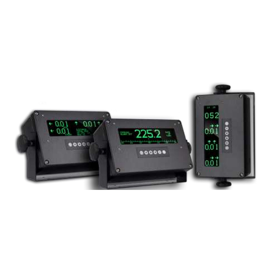
AMI Installation KW919 Doc No: AMI IM919 KW991-HR HEADING DISPLAY INTRODUCTION A bright green vacuum fluorescent dot matrix display presents ships heading from the gyro or magnetic compass. The VF display overcomes the disadvantages of other electronic displays such as LCD, such that it can be seen in dark environments, and has a higher contrast. -
Page 41: Installation Notes
AMI Installation KW919 Doc No: AMI IM919 INSTALLATION NOTES SITING Pre-planning and fore thought is essential for the practical siting of the display for best visibility and access. It should be mounted so that it can be viewed from most positions on the bridge, and with consideration against the bright sunlight. - Page 42 AMI Installation KW919 Doc No: AMI IM919 COMMON TYPES OF GYRO TRANSMISSIONS SYNCHRO TYPES AMUR CC150 115v ref. 50/60v 500Hz sigs, Synchro 360:1 ANSHUTZ Std 4 Std 6 50/60v ref. 20/24v 50/60Hz sigs, Synchro 360:1 HOKUSHIN PY76-N2 115v ref. 90v sigs, 360:1 Synchro, double-check. KURS 4 110v ref.
- Page 43 AMI Installation KW919 Doc No: AMI IM919 UNSMOOTHED RECTIFIED STEPPER This is raw rectified. You can measure using a ‘scope. On a Multimeter you can measure a voltage on AC range whereas with pure DC you should not measure a voltage.
-
Page 44: Kw991-Hr Heading Display Operator's Guide
AMI Installation KW919 Doc No: AMI IM919 KW991-HR HEADING DISPLAY OPERATOR’S GUIDE KEY PAD FUNCTIONS Switch off Display illumination. Switch on Display illumination. Increase illumination. Increase OCA window. Decrease illumination. Decrease OCA window. Hold for 3 seconds to enter alignment mode. Keep holding then use INC and DEC to align heading. -
Page 45: Off Course Alarm
AMI Installation KW919 Doc No: AMI IM919 OFF COURSE ALARM The alarm is OFF when disabled or the limit window is set to zero. The display and audio alarms become active by toggling the button. The Off Course Alarm compares the set heading and the actual heading ideally they should always stay the same. -
Page 46: Approximate Cable Requirements
AMI Installation KW919 Doc No: AMI IM919 APPROXIMATE CABLE REQUIREMENTS NOTE! All cables (with the exception of the Antenna RG213 and the Gyro Signal) originate from the MEU. The MEU is normally located in the BRIDGE or an adjacent compartment. 200 to 280 Metres 6 Core Screened 2.5mm each conductor. - Page 47 AMI Installation KW919 Doc No: AMI IM919 This Page Is Intentionally Blank Page 47 of 72 Manual SMIDS Installation Manual Iss02 Rev13.docx...
- Page 48 AMI Installation KW919 Doc No: AMI IM919 Cable Types Cable 1 3 Core 13 amp Cable 2 6 Core Screened. Conductor Thickness 2.5mm Low Impedance to ensure minimum of 12v DC reaches the forward Sensor. Cable 3 6 Core Screened. Conductor thickness 1.0mm Current Rating 10 amp.
- Page 49 AMI Installation KW919 Doc No: AMI IM919 This Page Is Intentionally Blank Page 49 of 72 Manual SMIDS Installation Manual Iss02 Rev13.docx...
- Page 50 AMI Installation KW919 Doc No: AMI IM919 M.E.U. – Terminal Connections Equipment Signal Termination CORE Colour/No CABLE Type MEU Termination AC IN LINE 1 (AMI-1) SK1-1 (LNE) SHIP SUPPLY LINE 2 SK1-3 (LINE) KW993 (24V+) SK1-1 (AMI-2) SK6-1 (24V+) G.R.A.C.I.E. (0V) SK1-2 SK6-2 (0V)
- Page 51 AMI Installation KW919 Doc No: AMI IM919 This Page Is Intentionally Blank Page 51 of 72 Manual SMIDS Installation Manual Iss02 Rev13.docx...
- Page 52 AMI Installation KW919 Doc No: AMI IM919 M.E.U. – Terminal Connections Equipment Signal Termination CORE Colour/No CABLE Type MEU Termination GYRO NMEA 0183 A (AMI-5) SK9 (NMEA 0183 A) (NMEA 0183) NMEA 0183 B SK9 (NMEA 0183 B) SPEED LOG NMEA 0183 A (AMI-5) SK10 (NMEA 0183 A)
- Page 53 AMI Installation KW919 Doc No: AMI IM919 This Page Is Intentionally Blank Page 53 of 72 Manual SMIDS Installation Manual Iss02 Rev13.docx...
- Page 54 AMI Installation KW919 Doc No: AMI IM919 M.E.U. – Terminal Connections Equipment Signal Termination CORE Colour/No CABLE Type MEU Termination KW991-ND (24V+) SK3-1 (AMI-3) SK15-1 (24V+) NAVIGATORS (0V) SK3-3 SK15-2 (0V) SMIDS DISPLAY (DATA IN A) SK2-1 SK15-3 (DATA OUT A) (DATA IN B) SK2-2 SK15-4 (DATA OUT B)
- Page 55 AMI Installation KW919 Doc No: AMI IM919 This Page Is Intentionally Blank Page 55 of 72 Manual SMIDS Installation Manual Iss02 Rev13.docx...
- Page 56 AMI Installation KW919 Doc No: AMI IM919 M.E.U. – Terminal Connections Equipment Signal Termination CORE Colour/No CABLE Type MEU Termination NMEA 0183 (AMI-5) (NMEA A) SK20-1 (NMEA OUT A) OUTPUT FOR (0V) SK20-2 (0V) NAV SYSTEMS (NMEA B) SK20-3 (NMEA OUT B) (OPTION) (SCREEN) SK20-4 (SCREEN)
- Page 57 AMI Installation KW919 Doc No: AMI IM919 This Page Is Intentionally Blank Page 57 of 72 Manual SMIDS Installation Manual Iss02 Rev13.docx...
- Page 58 AMI Installation KW919 Doc No: AMI IM919 M.E.U. – Terminal Connections (Optional Equipments) Equipment Term Signal CORE Colour/No JB 1 CORE Colour/No CABLE Type MEU Termination (AMI-4) PL1-2 (24V+) JB1-1 SK18-1 (24V+) KW994-BTTX cB-RBS433 PL1-1 (0V) JB1-2 SK18-2 (0V) POWER PL1 Pin 2 (NMEA A) JB1-3...
- Page 59 AMI Installation KW919 Doc No: AMI IM919 This Page Is Intentionally Blank Page 59 of 72 Manual SMIDS Installation Manual Iss02 Rev13.docx...
- Page 60 AMI Installation KW919 Doc No: AMI IM919 KW991-HR – Terminal Connections Equipment Signal Termination CORE Colour/No CABLE Type KW991 Termination SK1-1 (+5V) SK1-2 (+5V) SK1-3 (D1) SK1-4 (D2) SK1-5 (D3) SK1-6 (0V) SMIDS MEU (AMI-3) (DATA OUT A) SK8-3 SK2-1 (NMEA IN A 1) (DATA OUT B) SK8-4 SK2-2 (NMEA IN B 1)
- Page 61 AMI Installation KW919 Doc No: AMI IM919 This Page Is Intentionally Blank Page 61 of 72 Manual SMIDS Installation Manual Iss02 Rev13.docx...
-
Page 62: Smids Installation Data
SMIDS INSTALLATION DATA Pre Installation Checks Comments Bow cable Continuity Insulation Port Wing cable Continuity Insulation Stbd Wing cable Continuity Insulation Mains supply available Gyro Type Pre Power Up Checks Comments Bow Antenna cable Continuity ... - Page 63 AMI Manual KW919 Doc No: AMI TM919 CLASSIFICATION: Commercial In Confidence This Page Is Intentionally Blank Page 63 of 72...
- Page 64 AMI Manual KW919 Doc No: AMI TM919 CLASSIFICATION: Commercial In Confidence 1. EPROM issue SMIDS Displays SMIDS 2. EPROM issue GRACIES GRACIE 3. EPROM issue M.E.U. 4. EPROM issue Heading Display 5. Check and note GPS / GLONASS reception strengths 6.
- Page 65 AMI Manual KW919 Doc No: AMI TM919 CLASSIFICATION: Commercial In Confidence This Page Is Intentionally Blank Page 65 of 72...
-
Page 66: Equipment Locations
AMI Manual KW919 Doc No: AMI TM919 CLASSIFICATION: Commercial In Confidence EQUIPMENT LOCATIONS Page 66 of 72... - Page 67 AMI Manual KW919 Doc No: AMI TM919 CLASSIFICATION: Commercial In Confidence This Page Is Intentionally Blank Page 67 of 72...
- Page 68 AMI Manual KW919 Doc No: AMI TM919 CLASSIFICATION: Commercial In Confidence IEC60945: TÜV Certificates: SJ613140-002 Vibration SX613140-004 High Temperature SX613140-005 Damp Heat Cyclic SX613140-006 Low Temperature OO613140/01 EMC Lloyds Certificate for additional Tests: 05/00024 Vibration, Salt Spray and Enclosure Protection IEC61023: TÜV Test Report: RM200591-01...
- Page 69 AMI Manual KW919 Doc No: AMI TM919 CLASSIFICATION: Commercial In Confidence Page 69 of 72...
- Page 70 AMI Manual KW919 Doc No: AMI TM919 CLASSIFICATION: Commercial In Confidence Page 70 of 72...
- Page 71 AMI Manual KW919 Doc No: AMI TM919 CLASSIFICATION: Commercial In Confidence NOTES Page 71 of 72...
-
Page 72: Ami Marine (Uk) Ltd
Tower Lane Eastleigh Hants SO50 6NZ A full explanation of AMI Marine (UK) Ltd warranty conditions can be found on our web site or requested via email. * Terms of Service and Policies are subject to change without notice. ----------------------------------------------------------------------------------------------------------------------------------------- Please complete and return to AMI Marine either by post to the above address or by email to technical@amimarine.net...
Need help?
Do you have a question about the KW919 SMIDS and is the answer not in the manual?
Questions and answers