Table of Contents
Advertisement
Quick Links
Advertisement
Table of Contents

Subscribe to Our Youtube Channel
Related Manuals for Boss MXA130


Summary of Contents for Boss MXA130
- Page 1 Installation and operating manual MXA130 & MXA230 Pressurisation Units BOSS™, ASHCROFT WAY, CROSS POINT BUSINESS PARK, COVENTRY, UK, CV2 2TU BOSS™ Technical Team - Tel:03330 341920 Email: BOSStechnicalteam@bssgroup.com Last updated: 25th September 2024 V1...
-
Page 2: Table Of Contents
Table of contents 1. Warranty 2. Liability 3. Copyright 4. About this manual 4.1. Conventions symbols in this manual 4.2. Typography 5. Safety 5.1. Incoming goods 5.2. Operations location 5.3. Electrical 5.4. Staff qualification 6. Product description 6.1. Operating principle 6.2. - Page 3 MXA130 & MXA230 10. Maintenance 10.1. Maintenance intervals 10.2. Visual inspection 10.3. Interrogate controller 10.4. Test unit operation 11. Decommissioning / Dismantling 12. Appendix 1. Icon library 13. Appendix 2. Markings Appendix 3. Troubleshouting guide...
-
Page 4: Warranty
MXA130 & MXA230 1. Warranty The warranty on equipment supplied covers manufacturing defects, under our standard terms and conditions of sale, where items with a proven manufacturing defect are replaced at the point of sale. We understand the importance of providing timely support to ensure a smooth and satisfactory experience with our product. -
Page 5: Liability
We reserve the right to make technical changes subject to the future development of the Boss product referred to in this publication. Hence no rights may be derived from technical data, descriptions and illustrations. Technical pictures, drawings and graphs do not necessarily correspond to the actual assemblies or parts as delivered. -
Page 6: About This Manual
MXA130 & MXA230 4. About this manual The following pages list the information, specifications, measures and technical data that allow the relevant personnel to use this product safely and for the intended purpose. Responsible persons or those engaged by them carrying out the required services must read this manual attentively and understand it. -
Page 7: Typography
MXA130 & MXA230 4.2. Typography This manual makes use of different typography to identify different types of information. Italics Key words and phrases (Round Brackets) Used to identify a button on the digital controller [Square Brackets] A parameter on the digital controller <Inequality... -
Page 8: Safety
Any attempts to access the internals of the unit without the correct equipment will invalidate the Boss Warranty and will be classified as used in an improper manner, according to our General Conditions of Sale. -
Page 9: Electrical
Without prejudice to the considerations of the insurer/Operator, it is recommended that the electrical equipment of the MXA130 & MXA230 be inspected and documented together with the heating/cooling unit no less than every 12 months (see also DIN EN 60204-1 2007). -
Page 10: Staff Qualification
A competent person should be chosen who has available a team of employees with the necessary breadth of knowledge and experience. Operating instructions are transferred by BOSS representatives or others assigned by them during delivery negotiations or on demand. - Page 11 MXA130 & MXA230 On-site services include transportation, the preparation of an operations room with the requisite foundation engineering to accommodate the system, and the requisite hydraulic and electrical connections, the electrical installation for the power source of the expansion automat and installation of the signal leads for the IT equipment.
-
Page 12: Product Description
(e.g. slow leaks, air venting, etc.). The MXA130 & MXA230 the latest in pump digital pressurisation technology for light commercial and residential buildings. They are a slim, wall-mounted top-up pressurisation unit, with a top-up flow rate of up to 4,5 l/min. -
Page 13: Technical Datasheet
Drain 21.5 Waste pipe Maximum inlet pressure 10 Bar Maximum delivery pressure MXA130 / 3 Bar MXA230 MXA130/ MXA230 Nominal flow rate MXA130 / MXA230 (1 0,5l/min bar) Electrical details Supply voltage 230 Volt Frequency 50 Hz Full load current MXA130 / MXA230 0.3A... - Page 14 MXA130 & MXA230 Environmental data Power consumption (Standby) MXA130 / MXA230 Power consumption (Filling) Operation conditions Maximum temperature at inlet: 45°C Maximum temperature at outlet: 85°C Ambient temperature range: 5°C / 45°C Storage conditions Temperature 5°C / 45°C Humidity 60….70% relative humidity, non-condensing Keep the unit in a locked, frost free, non-condensing and dry area, protect the unit from solar &...
-
Page 15: Installation Requirements
MXA130 & MXA230 7. Installation requirements The MXA130 & MXA230 is a wall mounted unit and should be installed at a suitable eye level, where the screen is easy to read and maintenance remains practical and possible. The wall of the set-up location for the MXA130 &... - Page 16 MXA130 & MXA230 A mains cable is provided with the unit. A mains cable length of 2 metres may not be exceeded if replacement of a cable is necessary. Two WRAS approved flexible hoses with isolation valves are provided with the unit.
-
Page 17: Installation Diagram
MXA130 & MXA230 7.1. Installation diagram... -
Page 18: Clearance Requirements
MXA130 & MXA230 7.2. Clearance requirements Clearance guidelines for service & repair... -
Page 19: Hydraulic Connections
MXA130 & MXA230 7.3. Hydraulic connections From the “Manual-mode” in the controller menu, a testing routine can be triggered to check if the device is set up correctly and working accordingly. Each actuator (valve) can be operated separately with a maximum run-time of 2 minutes. -
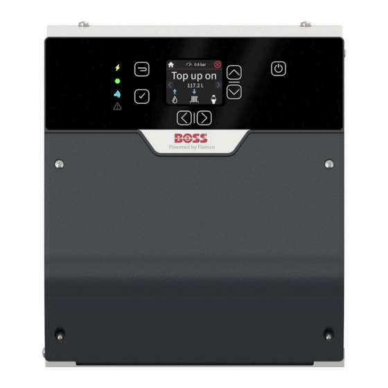
Page 20: Controller
MXA130 & MXA230 7.4. Controller A clarification of menu icons, function and location can be found in Appendix 1: Icon library. MXA130 & MXA230 Identification Description Pinout Power indicator (orange=power) Status indicator (green=ok automat running) Bluetooth not available Error/alarm (red=alarm/error active) - Page 21 MXA130 & MXA230 Mains power connector 3 PE Mains grommet Not Available System pressure sensor 1 +VDC 2 signal 3 GND Tank level sensor 1 +VDC 2 signal 3 GND Not Available Not Available Not Available Not Available Not Available...
-
Page 22: Electrical Installation
The Boss equipment must be connected to a mains isolator switch with a contact gap of at least 3 m. It is recommended the switch should be installed within 2m of the equipment. -
Page 23: Default Fail-Safe Software Settings And Wiring
MXA130 & MXA230 8.2. Default fail-safe software settings and wiring Max SA @ 230V AC non-inductive load Inductive loads such as motors lower the maximum current the relay will reliably take. Actual figures depend on the inductive load but typical estimate is 50%, so 2.5 amp inductive. -
Page 24: Wiring Table For Vfc Relay And Bms
MXA130 & MXA230 VFC3 (P29 terminal): Use for a fail-safe low pressure alarm use to shut down boiler and circulation pumps Connect to COM and NO; set these options: • Invert Polarity = Yes • System pressure to too low = Yes •... -
Page 25: Operation
MXA130 & MXA230 9. Operation Below is an overview of how the settings on a pressurisation unit must be considered for normal top-up operation. Close, conflicting or overlapping settings will cause system instability and nuisance alarm conditions. If in any doubt please seek advice from a Sealed System... - Page 26 MXA130 & MXA230 The Differential setting represents the allowable pressure loss before the pump activates and restores the cold fill pressure. The Differential setting must not be greater than the system venting allowance. This will ensure that the system remains fully flooded during normal topup conditions.
-
Page 27: Shut-Down Procedure
MXA130 & MXA230 9.1. Shut-down procedure Ensures water in the supply pipe to the product is refreshed every 3-7 days. The tank is then left empty to reduce the risk of water borne diseases. The time can be set to adjust for different pipe lengths. -
Page 28: Restarting
Please ensure that when the system cools down or warms up, the minimum or maximum system pressure does not exceed or fall below the permitted operating pressure. Check the MXA130 & MXA230 operation once power supply has been restored and, if necessary, set the actual date and time values (overview menu options). -
Page 29: Maintenance
Maintenance and repairs Maintenance and repairs may only be carried out when the system is shut down or if the MXA130 & MXA230 is not required to monitor or operate. The power supply must remain off for the period of the work. -
Page 30: Maintenance Intervals
5 Years after first commissioning, the MXA130 & MXA230 will need an annual service to reset the reminders for the annual service. It is the building owners responsibility to book the annual service to reset the controller. -
Page 31: Visual Inspection
MXA130 & MXA230 10.2. Visual inspection A basic visual inspection will highlight the majority of potential faults on a pressurisation unit. It is recommended to perform a visual inspection annually. However, due to the simplicity of performing these checks, frequent inspections are encouraged. -
Page 32: Decommissioning / Dismantling
MXA130 & MXA230 Decommissioning / Dismantling At the end of the service life or at planned shut-down of the equipment, please refer to chapter: 9.1 “Shut-down procedure” and follow the steps. The unit is separated from the power supply. The hydraulic system connection and top-up connection should be closed off. -
Page 33: Appendix 1. Icon Library
MXA130 & MXA230 12. Appendix 1. Icon library Icon Description Location Home Accept/Confirm Arrow left & right System OK System at warning System at fault Menu Language > > Date & time > > Date > > > Time >... - Page 34 MXA130 & MXA230 Mains supply > System connection Drain connection Legionella protection > Serial number > Settings General settings > System info > Service info Maintenance > Next maintenance due date Error logbook > Operating Hours > Login VFC relay >...
- Page 35 MXA130 & MXA230 Factory reset > > Login required to activate manual mode (Chapter 10) Firmware update > > Login required to activate manual mode (Chapter 10)
-
Page 36: Appendix 2. Markings
MXA130 & MXA230 13. Appendix 2. Markings Product label Voltage warning label... -
Page 37: Appendix 3. Troubleshooting Guide
MXA130 & MXA230 14. Appendix 3. Troubleshooting guide Please note that incorrect set-up conditions can lead to repeated errors and inhibit the intended use. Error # Notification Problem Solution Warnings The isolation valve at the Open the isolation valves at High pressure bottom of the unit is closed. - Page 38 MXA130 & MXA230 System too small for the unit Check if the system meets Self-learning the size requirements for the correction error unit. Place an expansion vessel System has no flexibility for in the system. pressure changes Check the connection System pipe diameter is too requirements of the unit.
- Page 39 MXA130 & MXA230 Tank level sensor not Tank level sensor Check sensor wiring connected no signal Tank level sensor failed Replace sensor Tank level sensor Short circuit in wiring Check sensor wiring short circuit Short circuit in sensor Replace sensor...
- Page 40 MXA130 & MXA230 High pressure The isolation valve at the Open the isolation valves bottom of the unit is closed. at the bottom of the unit. The system pressure has Decrease system risen above High pressure pressure using a suitable setpoint.
Need help?
Do you have a question about the MXA130 and is the answer not in the manual?
Questions and answers