Table of Contents
Advertisement
Quick Links
User Notes
BEAMWATCH
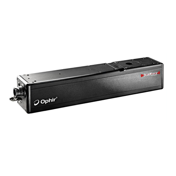
NON-CONTACT BEAM PROFILER FOR MULTI-KILOWATT NIR
(950–1100nm) AND VIS (420–635nm) WAVELENGTH LASERS
OPHIR USA
3050 NORTH 300 WEST
NORTH LOGAN, UTAH 84341
(800) 383-0814 OR (435) 753-3729
®
-PLUS-45
8J06013 - REV 01 - 23/Aug/2023
FAX: (435) 753-5231
SERVICE.OPHIR.USA@MKSINST.COM
SALES.OPHIR.USA@MKSINST.COM
WWW.OPHIROPT.COM
Advertisement
Table of Contents

Related Manuals for OPHIR mks BEAMWATCH-PLUS-45


Summary of Contents for OPHIR mks BEAMWATCH-PLUS-45
- Page 1 8J06013 - REV 01 - 23/Aug/2023 User Notes ® BEAMWATCH -PLUS-45 NON-CONTACT BEAM PROFILER FOR MULTI-KILOWATT NIR (950–1100nm) AND VIS (420–635nm) WAVELENGTH LASERS OPHIR USA FAX: (435) 753-5231 3050 NORTH 300 WEST SERVICE.OPHIR.USA@MKSINST.COM NORTH LOGAN, UTAH 84341 SALES.OPHIR.USA@MKSINST.COM (800) 383-0814 OR (435) 753-3729...
-
Page 2: Table Of Contents
USER NOTES 8J06013 - REV 01 - 23/Aug/2023 Table of Contents List of Figures and Tables ......................... 3 1 Safety Information ..........................4 Safety Procedures and Precautions ................... 4 Symbols Used in This User Note ....................4 2 Information ............................5 Introduction .......................... -
Page 3: List Of Figures And Tables
USER NOTES 8J06013 - REV 01 - 23/Aug/2023 List of Figures and Tables Figure 1: Operating Space Chart in the NIR Range ....................10 Figure 2: Operating Space Chart in the VIS range ....................11 Figure 3: Minimum Linear Power Density in the NIR Range ................... 12 Figure 4: Minimum Linear Power Density in the VIS Range ................... -
Page 4: Safety Information
DO NOT SUBSTITUTE PARTS OR MODIFY INSTRUMENT Do not install substitute parts or perform any unauthorized modification to the instrument. Return the instrument to an Ophir Calibration and Service Center for service and repair to ensure that all safety features are maintained. OPTICAL RADIATION HAZARDS BeamWatch is designed for use with high power lasers and therefore safety precautions must be taken. -
Page 5: Information
Measurements are taken by imaging the Rayleigh scatter of the beam from the side using conventional cameras making BeamWatch ideal for measurements of high-power lasers. Ophir has measured beams up to 100 kilowatts. BeamWatch provides simultaneous measurements of multiple profiles along the beam caustic in the camera field- of-view (FOV). -
Page 6: Equipment
USER NOTES 8J06013 - REV 01 - 23/Aug/2023 2.2 Equipment ¼” Polyurethane tubing 10ft BeamWatch-Plus-45 Glass Inserts Ethernet Cable 4.5m Gigabit to USB 3.0 Adapter Power Supply Cable Power Supply Adapter Kit User documentation: Alignment Tool • BeamWatch-Plus-45 User Notes •... -
Page 7: Optional Equipment
10kW water cooled power sensor • 30kW water cooled power sensor • 100kW water circulated power sensor • ® Juno USB PC interface • ® EA-1 Ethernet PC interface Consult your Ophir Representative or call Ophir’s Sales Department for ordering information. 7 | BEAMWATCH-PLUS-45... -
Page 8: Specifications
USER NOTES 8J06013 - REV 01 - 23/Aug/2023 2.4 Specifications Table 1: BeamWatch-PLUS-45 Specifications BeamWatch-PLUS-45 Beam Profiling Wavelength 420–635 nm 950–1100nm Minimum linear power 230 W/cm 34 kW/cm density Minimum Power 400W Minimum focus spot 45 µm Field of view (FOV) 9.01mm x 2.99mm FOV resolution 5.5µm... -
Page 9: Operating Limits
USER NOTES 8J06013 - REV 01 - 23/Aug/2023 BeamWatch-PLUS-45 Power 12 Volts DC, 1.67 Amps max, 100-240V AC Clean Dry Gas: approximately 35 PSI / 2.5 BAR; Particulate purge Particle size: < 5µm, oil and water free Weight 3.9 kg Dimensions 16 x 7 x 35in. - Page 10 USER NOTES 8J06013 - REV 01 - 23/Aug/2023 Figure 1: Operating Space Chart in the NIR Range 10 | BEAMWATCH-PLUS-45...
- Page 11 USER NOTES 8J06013 - REV 01 - 23/Aug/2023 Figure 2: Operating Space Chart in the VIS range 11 | BEAMWATCH-PLUS-45...
- Page 12 USER NOTES 8J06013 - REV 01 - 23/Aug/2023 Linear power density also plays a role in the operating space. The charts below show the required minimum power vs. focus spot size for a Gaussian beam. Figure 3: Minimum Linear Power Density in the NIR Range Figure 4: Minimum Linear Power Density in the VIS Range The equation to estimate the maximum spot size is derived from the linear power density equation: ��...
-
Page 13: Hardware Configuration
USER NOTES 8J06013 - REV 01 - 23/Aug/2023 3 Hardware Configuration This chapter provides instructions to setup and start using your BeamWatch. 3.1 BeamWatch Initial Setup The BeamWatch unit must be mounted to a stable surface where the laser can pass through the entrance and exit apertures unobstructed. -
Page 14: Mounting For Elliptical Beams
USER NOTES 8J06013 - REV 01 - 23/Aug/2023 Figure 6: BeamWatch Mounting After the BeamWatch is mounted, measure the distance from any desired reference point on the laser delivery head to the top face of the BeamWatch as shown in Figure 7. This value is the distance of the laser and must be entered into the software during setup (refer to the BeamWatch Software User Guide). -
Page 15: Cup Aperture
3.2 Beam Dump A suitable beam dump is required. An Ophir Power Sensor rated for the power of the laser is recommended. Other options are acceptable, but must have minimal backscatter, such as a cone type or black absorber power sensor. -
Page 16: Beamwatch Electrical Connections
USER NOTES 8J06013 - REV 01 - 23/Aug/2023 FOV using a clean, dry gas source. Air, Nitrogen, or Argon is recommended at approximately 10 SLPM (35 PSI / 2.5 BAR). Connect the provided ¼” hose to the gas source as shown in Figure 10. Figure 10: Particulate Purge Connections 3.4 BeamWatch Electrical Connections Refer to the connection diagram in Figure 11 for the steps below. -
Page 17: Wavelength Insert
USER NOTES 8J06013 - REV 01 - 23/Aug/2023 Connect the provided power cord to the power port on the BeamWatch unit. Connect the remaining end into a surge protected 100-240 VAC outlet. Connect one end of the provided Ethernet cable to the data source on the BeamWatch unit. Connect the remaining end into an Ethernet port on the PC, or connect to the Gigabit to USB adapter and connect the adapter to a USB 3.0 port. - Page 18 USER NOTES 8J06013 - REV 01 - 23/Aug/2023 Figure 13: Alignment Tool with the Cutout Facing Front For accurate results the beam must be aligned with the center of the input aperture, NOTE perpendicular to the top of the unit. A beam offset in any direction can produce inaccurate results.
- Page 19 USER NOTES 8J06013 - REV 01 - 23/Aug/2023 Figure 15: Alignment of the BeamWatch Device The beam is displayed in the BeamWatch software as an ellipse as shown in the images below. It may be necessary to adjust the Exposure and/or Frame Summing to bring the alignment beam to a viewable level.
- Page 20 USER NOTES 8J06013 - REV 01 - 23/Aug/2023 Figure 16: Beam Display when Using the Alignment Tool 20 | BEAMWATCH-PLUS-45...
-
Page 21: Final Alignment Steps
USER NOTES 8J06013 - REV 01 - 23/Aug/2023 3.7 Final Alignment Steps Refer to Figure 17 for the following steps. Figure 17: Alignment Bounds in the 2D Beam Display Window Once the beam is aligned remove the alignment tool and switch from the guide beam to the high-power beam. -
Page 22: Storing The Device
USER NOTES 8J06013 - REV 01 - 23/Aug/2023 Figure 18: Diagram of Misaligned Beams • The red beam is off in the view of the Y axis. It needs to be moved down and left to center. • The blue beam is off in both axes and appears close to the insides of the views. It needs to be moved up to center. -
Page 23: Dimensions
USER NOTES 8J06013 - REV 01 - 23/Aug/2023 4 Dimensions 23 | BEAMWATCH-PLUS-45... - Page 24 USER NOTES 8J06013 - REV 01 - 23/Aug/2023 Copyright © 2023 by MKS Instruments, Inc. and its affiliates. All rights reserved. No part of this work may be reproduced or transmitted in any form or by any means, electronic or mechanical, including photocopying and recording, or by any information storage or retrieval system, except as may be expressly permitted in writing by MKS Instruments, Inc.
Need help?
Do you have a question about the mks BEAMWATCH-PLUS-45 and is the answer not in the manual?
Questions and answers