Table of Contents
Advertisement
Quick Links
Advertisement
Table of Contents

Related Manuals for ABB MEGADRIVE-LCI water-cooled


Summary of Contents for ABB MEGADRIVE-LCI water-cooled
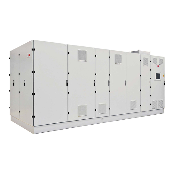
- Page 1 — SYSTEM DRIVES MEGADRIVE-LCI water-cooled User manual OWNING ORGANIZATION DATE STATUS SECURITY LEVEL System Drives, ABB Switzerland Ltd. 2024-03-13 Approved Public DOCUMENT KIND DOCUMENT ID. REV. LANG. PAGE User manual 3BHS343595 E01 1/153 © Copyright 2009 ABB All rights reserved.
- Page 2 This document contains information about one or more ABB products and may include a description of or a reference to one or more standards that are relevant to the ABB products. The presence of any such description of a standard or reference to a standard is not a representation that all of the ABB products referenced in this document include all the features of the described or referenced standard.
-
Page 3: Table Of Contents
CONTENTS — CONTENTS 1. About this manual......................... 11 1.1. Equipment covered by this manual ..................... 11 1.2. Terms and abbreviations........................ 11 1.3. Structure of the user documentation ..................12 1.4. Related documents.......................... 12 1.4.1. Service documents ......................12 1.4.2. Specifications and guidelines................... 13 1.5. - Page 4 CONTENTS 3.3.3. Bypass disconnector for output transformer.............. 42 3.4. Other features ..........................43 3.4.1. Door locking.......................... 43 3.4.1.1. Locks and key types....................43 3.4.2. Door safety switches......................44 3.4.3. Door safety switches with interlock (option)............... 45 3.4.4. Heating system (option) ....................46 3.5.
- Page 5 CONTENTS 6.6.1. Preparing the cable entry and the cables ..............67 6.6.2. Connecting the cables ......................67 6.6.2.1. Checking cable insulation ..................67 6.6.2.2. Bolted busbar connections .................. 68 6.7. Final checks............................69 7. Commissioning ........................70 7.1. Overview ............................70 7.1.1. Required qualification......................70 7.1.2.
- Page 6 CONTENTS 9.2.4. User passwords ........................91 9.3. LCT menus............................92 9.3.1. Diagrams menu ........................93 9.3.2. Events menu ......................... 95 9.3.2.1. Operation buttons in the Events menu............. 96 9.3.3. Operations menu ........................ 98 9.3.3.1. Selecting a data point.................... 99 9.3.3.2. Configuring an analog meter for a selected data point ......100 9.3.4.
- Page 7 CONTENTS 10.1.2. Maintenance schedule ......................142 10.1.3. Logbook..........................142 10.1.4. NETA-21 remote monitoring tool ...................142 10.1.5. Spare parts...........................142 10.2. Standard troubleshooting procedure..................143 10.3. Maintenance tasks ........................144 10.3.1. Safety............................ 144 10.3.2. De-energizing the drive ....................144 10.3.3. Connecting a grounding set....................145 10.3.4. Visual checks on the drive ....................147 10.3.5.
- Page 8 FIGURES — FIGURES Fig. 1. Product warning label examples (label placement depends on the drive) ... 22 Fig. 2. Drive system overview ....................27 Fig. 3. ICB opening timing diagram ..................29 Fig. 4. Drive overview ......................31 Fig. 5. Water-cooled thyristor stacks example ..............32 Fig.
- Page 9 FIGURES Fig. 38. Status bar ........................86 Fig. 39. Login window ......................89 Fig. 40. Diagrams menu ......................93 Fig. 41. Events menu ......................95 Fig. 42. Operations menu ...................... 98 Fig. 43. Control IT window ....................99 Fig. 44. Configure meter window ..................101 Fig.
- Page 10 Table 7 NETA-21 software account........................18 Table 8 Standards ............................... 19 Table 9 Excitation unit by drive type ......................41 Table 10 ABB arc resistant classes ........................47 Table 11 Lifting attachment specifications....................52 Table 12 Installation material per IP42 unit....................60 Table 13 Cable lug sizes ............................ 68 Table 14 Signals on the status bar .........................
-
Page 11: About This Manual
1.2. Terms and abbreviations The following table lists terms and abbreviations you should be familiar with when using this user manual. Some of the terms and abbreviations used in this user manual are unique to ABB and might differ from the normal usage. -
Page 12: Structure Of The User Documentation
ABOUT THIS MANUAL TABLE 1 Terms and abbreviations (continued) Term Definition LCI.W MEGADRIVE-LCI water-cooled LCI Control Terminal Local drive control device incorporating a touchscreen and a panel PC. LCI Converter Interface Board Line voltage RMS voltage of the main power supply of the drive... -
Page 13: Specifications And Guidelines
ABOUT THIS MANUAL 1.4.2. Specifications and guidelines Title ABB ID Auxiliary power and control cables guideline 3BHS813742 E01 1.5. Target groups and required qualifications The drive presented in this manual is part of an industrial environment where voltages are present that contain a potential hazard of electric shock and/or burn. For this reason, only personnel who have a thorough knowledge of the drive and the industrial environment and have obtained the required qualification must handle, install, operate, or maintain the drive. -
Page 14: Operation
ABB. Use of the drive outside the scope of the specifications is not permitted. Intended equipment use also implies that only spare parts recommended and approved by ABB must be used. Unauthorized modifications and constructional changes of the drive are not permitted. -
Page 15: Cyber Security Features
Internet. – Follow the remote access gateway setup recommendations to establish a network connection to the ABB Ability platform. – Restrict physical access to the drive and control network access to authorized personnel. -
Page 16: Pec Controller Security Features
ABOUT THIS MANUAL 1.7.2. PEC controller security features The PEC controller software fulfills the minimum cyber-security requirements by using security features of AC 800PEC platform. The following Ethernet ports are open by default to ensure that the system operates properly. TABLE 3 Open Ethernet ports for PEC controller software Port Service... -
Page 17: Table 4 Opens Ports For The Lct
ABOUT THIS MANUAL TABLE 4 Opens ports for the LCT Port Service Usage 102 / tcp Communication with AC 800PEC controller 135 / tcp msrpc Windows service 139 / tcp NetBIOS-ssn Windows service 445 / tcp Microsoft-ds? Windows service 3050 / tcp Gds_db Database access 3389 / tcp... -
Page 18: List Of Software Accounts
ABOUT THIS MANUAL 1.7.4. List of software accounts The following tables contain the login credentials. TABLE 5 Control terminal software accounts Account description User Password Windows user account LCTuser N/A (undisclosed) (local user account) Windows account N/A (undisclosed) (administrator) Operator Level 1 ABB1 LCT Application Operator Level 2... -
Page 19: Quality Certificates And Applicable Standards
The following certificates and conformity declarations are available with ABB: – ISO 9001 and ISO 14001 certificates stating that ABB Switzerland Ltd has implemented and maintains a management system that fulfills the requirements of the normative standards TABLE 8 Standards... -
Page 20: Document Conventions
ABOUT THIS MANUAL 1.9. Document conventions The document uses the following font formats and symbols. See also Section 2.1, “Safety messages and safety signs in this document”, page 21. Font formats Convention Description Prerequisite for a task Sequential procedural steps in a task –... -
Page 21: Important Safety Information
IMPORTANT SAFETY INFORMATION 2. Important safety information Read this material carefully before working on or around the equipment. Failure to do so can result in serious Injury or DEATH! Keep for future reference. 2.1. Safety messages and safety signs in this document This document uses ANSI Z535.6 signal words, ISO 7010 safety signs, and ISO 3864-2 colors to highlight safety-related information. -
Page 22: Product Safety Labels
IMPORTANT SAFETY INFORMATION 2.2. Product safety labels Product safety labels on the equipment alert you to the hazards that can occur when you work on or operate the equipment. – Always follow the instructions on the labels to avoid the hazard –... -
Page 23: Electrical Safety
IMPORTANT SAFETY INFORMATION 2.3. Electrical safety The following electrical safety instructions are based on EN 50110. 2.3.1. General safety instructions 1) Minimize hazards 2) Before energizing the drive: • Remove all foreign objects are from the drive • Fasten all internal and external covers securely •... -
Page 24: The 7 Steps That Save Lives
IMPORTANT SAFETY INFORMATION 2.3.2. The 7 steps that save lives ABB’s 7 steps that save lives concept is a series of actions that must take place prior to commencing work on or near electrical installations. 1) Prepare for the work: do an on-site risk assessment or job hazard analysis that considers the limits of approach for shock and arc-flash. - Page 25 IMPORTANT SAFETY INFORMATION 6) Protect against adjacent live parts and take special precautions when close to bare conductors. • Determine minimum approach distances, apply screening or shrouding, and when applicable, padlock both cable and busbar shutters. • If working within the restricted approach boundary or vicinity zone where inadvertent movement could cause contact with live parts, special precautions must be employed, such as the use of the properly rated insulated gloves and tools.
-
Page 26: Possible Residual Risks
IMPORTANT SAFETY INFORMATION 2.3.3. Possible residual risks Residual risks must be considered by the drive system integrator and/or plant owner when assessing the hazards of the equipment to personnel. The following risks can pose a hazard to drive system personnel: 1) Electric power equipment generates electro-magnetic fields which can cause a hazard to people with metal implants and / or a pacemaker. -
Page 27: Important Note - Main Circuit Breaker
IMPORTANT SAFETY INFORMATION 2.4. Important note - main circuit breaker The input circuit breaker (ICB) is a major protection device of the drive. If a serious fault occurs in the drive, the ICB must disconnect the main power supply to the drive immediately. The main power supply must be disconnected without delay on an open or trip command from the drive to prevent hazard to the personnel and further damage to the equipment. -
Page 28: Safety And Protection Requirements
For safety and protection reasons, the ICB must meet the stipulated minimum requirements of the specifications of ABB Medium Voltage AC drives. It is the system integrator's responsibility to ensure that the minimum requirements are met. The minimum requirements for the ICB are stated in this note and in the respective ICB specifications, which are available for each medium voltage drive from ABB. -
Page 29: Maintenance Recommendation
No hazard to personnel Maximum protection trip time Maximum safety trip time Fig. 3. ICB opening timing diagram In order to meet the stipulated safety requirements, ABB recommends one of the following: – ICB with 2 independent opening coils –... -
Page 30: Hardware And Features Of The Drive
HARDWARE AND FEATURES OF THE DRIVE 3. Hardware and features of the drive 3.1. Overview The MEGADRIVE-LCI is a variable speed drive for continuous operation (LCI.DR), soft starting (LCI.SO) of synchronous machines and for starting gas turbines (LCI.ST). For more information on the drive and applicable power and voltage, see: –... -
Page 31: General Units
HARDWARE AND FEATURES OF THE DRIVE Key: Water cooling unit DC-link unit Line-side terminal unit Converter unit Motor-side terminal unit Control unit Fig. 4. Drive overview 3.2. General units Regardless of the field of application and configuration, each air-cooled drive includes at least one of the following units: –... -
Page 32: Converter Unit
HARDWARE AND FEATURES OF THE DRIVE 3.2.1. Converter unit A converter unit consists of a rectifier and an inverter. Both use thyristor stacks of identical design and also contain heat sinks, snubber circuits and gate firing circuits. The rectifier converts the supply current to direct current. The inverter then converts the direct current into a three-phase alternating current that modulates into variable frequency and voltage depending on the process requirements. -
Page 33: Line-Side And Motor-Side Terminal Unit
HARDWARE AND FEATURES OF THE DRIVE 3.2.2. Line-side and motor-side terminal unit The standard terminal unit (one installed for each 3-phase system) consists of the following main components: – Busbars for the connection of the power cables from the transformer or to the motor –... -
Page 34: Dc-Link Unit
HARDWARE AND FEATURES OF THE DRIVE 3.2.3. DC-link unit The DC-link unit has an iron core inductor and is usually part of the drive cabinet, whereas some specialized drive systems use an external air or iron core inductor instead. Fig. 7. Water-cooled DC-link unit example with iron core PRODUCT DOCUMENT KIND DOCUMENT ID. -
Page 35: Control Unit
HARDWARE AND FEATURES OF THE DRIVE 3.2.4. Control unit Key: Control terminal (LCT) Gate firing circuits (MV-GDR or GDI) AC 800PEC S800 I/O system LCI converter Interface board (LIN) Combined Input/Output (CIO) Fig. 8. Control unit 3.2.4.1. Main components PRODUCT DOCUMENT KIND DOCUMENT ID. -
Page 36: Fig. 9. Control System
HARDWARE AND FEATURES OF THE DRIVE Key: Ethernet S800 - slow I/O NETA-21 Optical fiber cable CIO - Fast I/O AC 800PEC (10) Gate driver (11) Analog signals (12) Converter line side (rectifier) (13) Converter Machine side (Inverter) Fig. 9. Control system PRODUCT DOCUMENT KIND DOCUMENT ID. -
Page 37: Fig. 10. Ac 800Pec Controller
HARDWARE AND FEATURES OF THE DRIVE AC 800PEC The control part of the MEGADRIVE-LCI uses the AC 800PEC controller. The controller is the major component of the drive control system and performs general drive, motor control, and closed loop functions. The main internal control devices and the peripheral input and output interfaces to the customer communicate with the controller via optical fibers. - Page 38 HARDWARE AND FEATURES OF THE DRIVE Each LIN controls a 6-pulse thyristor bridge and fires the thyristors according to the magnetic or indirect light firing principle. It connects to the AC 800PEC via fast fiber optics and provides analog inputs for converter voltages and currents as well as digital contact inputs. Gate firing circuits Depending on the numbers of thyristors per branch, different firing principles apply.
-
Page 39: Cooling System
HARDWARE AND FEATURES OF THE DRIVE 3.2.5. Cooling system The drive uses a water-cooling unit (WCU) for heat dissipation. For more information, see “Appendix H - Water-cooling unit”. The converter cabinets are further ventilated by fans (featuring 2 out of 3 redundancy). Key: Pressure relief vents Fan unit... -
Page 40: Application-Specific Units
HARDWARE AND FEATURES OF THE DRIVE 3.3. Application-specific units If the drive is used for speed / torque control (LCI.DR) or soft starting (LCI.SO), it may also include the following units: – Excitation unit (standard in LCI.DR) – Bypass disconnector for the output transformer (used in LCI.SO only) –... -
Page 41: Synchronization Unit (Synchrotact 6)
HARDWARE AND FEATURES OF THE DRIVE Two types of excitation units are available: – AC excitation unit (ac-EXU) with an AC controller for synchronous machines with brushless exciter – DC excitation unit (dc-EXU) with a DC controller for synchronous machines with slip rings TABLE 9 Excitation unit by drive type Type Standard... -
Page 42: Bypass Disconnector For Output Transformer
HARDWARE AND FEATURES OF THE DRIVE 3.3.3. Bypass disconnector for output transformer The bypass disconnector (BPU) is only required for a soft starting application (LCI.SO) that uses an output transformer. A BPU allows for the bypassing the output transformer to run up the motor in the lower speed range (approximately 10% to 15% of nominal speed). -
Page 43: Other Features
HARDWARE AND FEATURES OF THE DRIVE 3.4. Other features 3.4.1. Door locking To ensure safety and prevent the doors from opening unintentionally, all doors are lockable. 3.4.1.1. Locks and key types To ensure that only authorized personnel are able to open medium voltage compartments, their locks use different inserts than the locks of the control and excitation unit. -
Page 44: Door Safety Switches
HARDWARE AND FEATURES OF THE DRIVE 3.4.2. Door safety switches Key: Safety switch location Safety switch Fig. 17. Door safety switch examples In addition to the locks, door safety switches monitor the doors of medium voltage compartments. When the door is opened, the drive trips. For details on the trip sequence, see the flow chart in “Appendix C - Electrical drawings including parts list”. -
Page 45: Door Safety Switches With Interlock (Option)
HARDWARE AND FEATURES OF THE DRIVE 3.4.3. Door safety switches with interlock (option) Some drives are fitted with optional combined door mounting and interlock safety switches. A safety switch contains an electro-magnetic lock that keeps the door closed until a safe drive state is achieved. -
Page 46: Heating System (Option)
HARDWARE AND FEATURES OF THE DRIVE 3.4.4. Heating system (option) The optional heating system protects electrical components of the drive from condensation. The heating system consists of heating elements with humidistats and thermostats. The humidistats and thermostats monitor the humidity and the temperature inside the cabinet. The heating system activates as soon as the temperature falls below and the humidity climbs above their predefined thresholds. -
Page 47: Arc Resistant Design (Option)
The optional “Arc Resistant Design” provides the drive with arc fault protection in accordance with IEC 62477-2. The ABB arc resistant classes in Table 10 indicate the type of arc proofing that a drive uses. Depending on the drive configuration, classes I and II are available for an LCI.W drive. -
Page 48: Transportation, Storage And Disposal
2. Check the drive and accompanying equipment for damage. 3. Compare the complete delivery with the purchase order and the packing list. 4. If parts are missing or damaged, immediately inform the shipping company and the ABB service organization. It is recommended to photograph the damages and send the photographs to ABB. -
Page 49: Lifting Attachment Types
These lifting attachments are intended exclusively for use with the MEGADRIVE-LCI equipment. Any use beyond this is strictly prohibited. ABB ID: ABB ID: ABB ID:... -
Page 50: Drive Lifting Guide
TRANSPORTATION, STORAGE AND DISPOSAL 4.4.2. Drive lifting guide Lifting plates are factory-installed on the base frame of the drive. If you need to reinstall the plates, see Section 4.4.4, “Installing or reinstalling lifting attachments”, page 52 before you begin. 1. Verify that the factory torque marks on the mounting bolts and washers of the lifting plates are aligned. -
Page 51: Lifting With Rotating Eyebolts
TRANSPORTATION, STORAGE AND DISPOSAL 4.4.3. Lifting with rotating eyebolts Rotating eyebolts are required for lifting fan units (delivered separately) onto the roof of the drive. The eyebolts are delivered with the loose parts for the drive. These instructions describe how to correctly use rotating eyebolts in lift operations. For installation instructions that use rotating eyebolts, see Chapter 5, “Mechanical installation”, page 55. -
Page 52: Installing Or Reinstalling Lifting Attachments
Only use the original lifting attachments and fasteners. Before use, always check the lifting attachments for damage, eg, corrosion and cracks. DO NOT attempt to lift equipment with a damaged lifting attachment; contact ABB for a replacement before you proceed. -
Page 53: Storage
The drive can be stored for up to one year in the original packaging as long as it is not damaged or opened. For information on longer storage periods, contact the ABB service organization. 4.5.2. Storing the drive If the drive is taken out of service for a longer time, proceed as follows: 1. -
Page 54: Warranty Information
4.5.3.1. Warranty information IMPORTANT! Check the spare parts immediately after receipt for damages. Report any damage to the shipping company and the ABB service organization. Observe the following to maintain spare parts in good condition and to keep the warranty valid during the warranty period: –... -
Page 55: Mechanical Installation
MECHANICAL INSTALLATION 5. Mechanical installation 5.1. Safety All installation work must be carried out by qualified personnel according to the site and equipment requirements and in compliance with local regulations. 5.2. Overview on the installation work Mechanical installation includes the following items: –... -
Page 56: Preparing The Floor
For the location of the fixing points, see “Appendix B - Mechanical drawings” – Before moving the cabinets to their final location, drill the fixation holes in the floor ∅ – For concrete floors, ABB recommends using wedge anchors ( 16 mm) Fig. 24. Concrete wedge anchor example PRODUCT DOCUMENT KIND DOCUMENT ID. -
Page 57: Joining Transport Units
MECHANICAL INSTALLATION 5.4. Joining transport units This section only applies to drives delivered into separate transport units that must be joined at the installation site. 1. Align the transport units as shown in “Appendix B - Mechanical drawings”. 2. Join the transport units with the supplied assembly material. The base frames of two adjacent units must be joint together by means of the supplied material. -
Page 58: Fixing The Cabinet To The Floor
MECHANICAL INSTALLATION 5. Join the pipe ends by means of appropriate pipe couplings (not needed for flexible piping). 6. Connect the copper earth bands located at one pipe end to the adjacent pipe end, in order to ensure electrical contact. 5.5. -
Page 59: Installing Cabinet Cooling Fans
MECHANICAL INSTALLATION 5.6. Installing cabinet cooling fans 5.6.1. Lifting a unit with a crane CAUTION Heavy objects! An IP42 cooling unit weighs 40 kg and an IP54 cooling unit weighs 98 → Use appropriate slings and shackles 1. Attach appropriate slings and shackles to the lifting brackets of a cooling unit. 2. -
Page 60: Installing Ip42 Roof-Mounted Cooling Units
MECHANICAL INSTALLATION 5.6.2. Installing IP42 roof-mounted cooling units One by one, install the IP42 roof-mounted cooling units on top of the PCU compartments that have the designated openings. TABLE 12 Installation material per IP42 unit Item Quantity Details Self-tapping Torx screws M6×16 Washers with sealing 6.8×1 (4.8×2.8) -
Page 61: Installing The Pressure Relief Vents (Arc-Rated Cabinets)
MECHANICAL INSTALLATION 5.7. Installing the pressure relief vents (arc-rated cabinets) Pressure relief vents are required on drives with arc-rated cabinets. Weight ~26 kg L × W × H 840 × 520 × 210 mm Fig. 26. Pressure relief vents Key: Cordless drill Torx bit 24 ×... -
Page 62: Fig. 28. Pressure Relief Vent Installation Example
MECHANICAL INSTALLATION Referring to Fig. 28: 1. Orientate the pressure relief vents with the baffle blades (arrows) pointing to the center of the drive. NOTE – You can see the orientation of the baffle blades through the grill on the underside. -
Page 63: Installing The Excitation Air Hoods
MECHANICAL INSTALLATION 5.8. Installing the excitation air hoods If your drive came with an excitation unit (EXU), you need to install the 2 roof-mounted air hoods. Weight ~15 kg L × W × H 770 × 440 × 160 mm Key: Cordless drill Torx bit... - Page 64 MECHANICAL INSTALLATION Referring to Fig. 30: 1. Verify that the fan cutouts on the EXU roof are free of obstructions (eg, cables and packaging material. 2. Manually lift the hood onto the cabinet roof. Align the mounting holes on the base of the air hood with the corresponding holes around the cutout.
-
Page 65: Electrical Installation
→ When the electrical installation is completed, the main and auxiliary power supply to the drive must not be switched on without the consent of the ABB commissioning personnel. → Take appropriate measures to prevent main and auxiliary power supply being switched on during installation. -
Page 66: Internal Electrical Wiring
ELECTRICAL INSTALLATION The drive includes optical fiber cables that span across the entire length of the drive and need to be reconnected in case of units delivered separately. Such cables are rolled back in the inside of the transport unit's cabinet. For easier identification, they are marked with appropriate labels at the two connecting terminals. -
Page 67: Power Cables, Ground Cables, Equipotential Bonding Conductor
ELECTRICAL INSTALLATION 6.6. Power cables, ground cables, equipotential bonding conductor For information on: – Block diagram, see “Appendix C - Electrical drawings including parts list”. – Designation, cross-reference and device identification conventions, see Converter hardware diagram in “Appendix C - Electrical drawings including parts list”. –... -
Page 68: Bolted Busbar Connections
ELECTRICAL INSTALLATION 6.6.2.2. Bolted busbar connections Material requirements Use stainless steel bolts and nuts with the appropriate steel grade and property class for the connection (recommended: A2-70; designation according to ISO 3506). Nuts with bonded coating can be used as an alternative to uncoated stainless steel nuts. Connection type Referring to Fig. -
Page 69: Tightening Torque
ELECTRICAL INSTALLATION Lubrication – If stainless steel bolts and nuts are used, lubricate the thread and head contact surface of the bolt using recommended pasts, eg, Molykote D paste. – If a coated nut (eg, with bonded molybdenum-disulfide [MoS ] coating) is used, the connection does not have to be lubricated. -
Page 70: Commissioning
The following sections provide an overview of the commissioning process for your drive. 7.1.1. Required qualification Commissioning, parameter adjustments and functional tests must be carried out only by qualified commissioning personnel that have been certified by ABB. 7.1.2. Commissioning procedure Information on the commissioning procedure and the start conditions for commissioning can be obtained from ABB. -
Page 71: Commissioning Checklist
COMMISSIONING 7.2. Commissioning checklist This checklist is designed to help you prepare the drive and associated equipment for commissioning. 7.2.1. Mechanical installation checklist 1) Drive installed according to the instructions in the user manual 2) Drive securely fastened to the floor (if applicable) ... -
Page 72: Motor Checklist
COMMISSIONING 7.2.3. Input circuit breaker (ICB) checklist 1) High-voltage connections completed 2) ICB ready to be tested with drive 3) ICB protection relay settings tested 4) Safety devices (eg, door locking mechanism) tested and in operation 7.2.4. -
Page 73: Miscellaneous Checklist
COMMISSIONING 7.2.7. Miscellaneous checklist 1) Sufficient number and correct type of spare parts available 2) Sufficient quantity of deionized water according to the information on the converter layout drawing available 3) Air conditioning of drive room ready for load run of drive ... -
Page 74: Operation
OPERATION 8. Operation The chapter outlines the local operation using the control terminal on the door of the control unit. Control of the drive via a PLC or higher-level control systems is not described in this chapter. If the drive is controlled from remote, see the appropriate manuals for information. 8.1. -
Page 75: Overview Of The Control Terminal
OPERATION 8.3. Overview of the control terminal The control terminal enables the operator to control the drive without restrictions if all requirements for normal operation are met. The functions of the control terminal include: – Switching on / off the auxiliaries –... -
Page 76: Starting The Drive Locally
OPERATION 8.4. Starting the drive locally It is recommended to have the following documents at hand when starting the drive locally for the first time after commissioning or after it has been taken out of service for a longer period: –... - Page 77 OPERATION Procedure 1. Touch the AUX ON button (auxiliaries on) to switch on the auxiliaries. After the auxiliaries have been switched on, the following message appears on the status bar of the control panel: MV READY (Medium voltage is ready) The input circuit breaker of the drive can now be closed.
-
Page 78: Stop Sequences
OPERATION 8.5. Stop sequences All drive-related messages mentioned in this section are displayed on the status bar of the control terminal. The buttons illustrated below are shown on the operation bar of the local control terminal. For more information on the status bar and the buttons, see Section 9.1.2, “Status bar”, page 86 and Section 9.4, “Operation bar and reference value input feature”, page 135, respectively. -
Page 79: Emergency-Off Push Button
OPERATION Electric braking takes place down to a speed of 1% of the rated speed. When this threshold has been reached, the drive switches off automatically. The drive can be stopped manually by touching the OP OFF button. The stop sequence is the same as described in Section 8.5.1, “Coasting down”, page 78. -
Page 80: Operation Of Doors With Interlock Switches (Option)
OPERATION 8.7. Operation of doors with interlock switches (option) Door interlock operation control requires (auxiliary) voltage. If you need to open the door when the converter is completely de-energized, see Section 8.7.3, “Emergency release of a door safety switch”, page 82 8.7.1. -
Page 81: Closing And Locking The Doors
OPERATION 8.7.2. Closing and locking the doors 1. Close the doors. 2. Bring the door handle in line with the door plate (1) and press the handle down (2) until it clicks in. 3. (Doors hinged on the left) Slide the locking bar right from the unlocked position (1) to the locked position (2). -
Page 82: Emergency Release Of A Door Safety Switch
OPERATION 8.7.3. Emergency release of a door safety switch DANGER Hazardous voltages! Touching energized components can be FATAL. → Before you unlock a safety switch, verify that the drive is de-energized. → DO NOT unlock the safety switches permanently. 8.7.3.1. Location of safety switches The doors of medium voltage units are equipped with safety switches. -
Page 83: Safety-Switch Settings
OPERATION 8.7.3.2. Safety-switch settings Key: Description Enables opening the door of a medium voltage unit whether the auxiliary voltage Unlocked is switched on or off. Direction of arrow indicates safety switch status, ie, locked or unlocked Release dial Locked Normal operating setting. To open the door of a medium voltage unit, the DC-link must be discharged and the auxiliary voltage must be switched on. -
Page 84: Local Control Terminal
LOCAL CONTROL TERMINAL 9. Local control terminal 9.1. LCT touch panel Fig. 36. Control terminal with touch panel PC The MEGADRIVE-LCI local control terminal (LCT) incorporates a touch panel PC with a Microsoft Windows operating system and programs specific to the MEGADRIVE-LCI. The menus described in this chapter are typical examples to illustrate the related instructions and functions. -
Page 85: User Interface Overview
LOCAL CONTROL TERMINAL 9.1.1. User interface overview The default start menu in the LCT touch panel is the Diagrams menu, which opens when the auxiliary supply voltage of the drive is switched on. Speed U rms U DC U rms I rms I DC I rms... -
Page 86: Status Bar
LOCAL CONTROL TERMINAL 9.1.2. Status bar Fig. 38. Status bar The status bar at the top of the Diagrams menu provides the following information: TABLE 14 Signals on the status bar Signal Status/value Description OFF / ON Status of auxiliary units (eg, cooling) OFF / ON Status of medium voltage supply OFF / ON... -
Page 87: Panel Control Button
LOCAL CONTROL TERMINAL 9.1.2.1. Panel Control button The Panel Control button is part of the status bar. To use the Panel Control button, you must be logged in with one of the following user authorizations: – Operator-Level-2 – Operator-Level-3 – Administrator The hand symbol on the Panel Control button changes its color depending on the control status: TABLE 15 Panel control button statuses... -
Page 88: Menu Bar
LOCAL CONTROL TERMINAL 9.1.3. Menu bar The menu bar takes you to different menus with various functions. They are described in: – “Login and logout procedures”, page 89 – “LCT menus”, page 92 – “Operation bar and reference value input feature”, page 135 9.1.4. -
Page 89: Login And Logout Procedures
LOCAL CONTROL TERMINAL 9.2. Login and logout procedures To perform operational commands, enter settings and use functions, you must be logged in as a user. Without logging in, you only have limited rights to perform changes, and you can only view process values and recorded data. -
Page 90: Automatic Logout Function
LOCAL CONTROL TERMINAL After entering the password, you are logged in and authorized to use the menu functions. • If no users are logged in, the login status in the status bar is a hyphen (-). • If a user is logged in, the login status in the status bar displays the name of the user. NOTE –... -
Page 91: User Authorizations
LOCAL CONTROL TERMINAL 9.2.3. User authorizations Table 17 describes the types of user authorizations that are available for the LCT. TABLE 17 Overview of user authorizations Item Function User authorizations Oper. Oper. Oper. Admin. level-1 level-2 level-3 Program Minimize, close Panel Control button Usage Events... -
Page 92: Lct Menus
LOCAL CONTROL TERMINAL 9.3. LCT menus The following sections provide an overview of the LCT menus: – “Diagrams menu”, page 93 – “Events menu”, page 95 – “Operations menu”, page 98 – “Parameters menu”, page 102 – “Slow trending menu”, page 114 –... -
Page 93: Diagrams Menu
LOCAL CONTROL TERMINAL 9.3.1. Diagrams menu The Diagrams menu shows a simplified block diagram with analog views of the current, voltage and power data of the drive. These views are not customizable. The configurable operation bar is at the bottom of the Diagrams menu. For more information, see Section 9.4.1, “Releasing the operation buttons”, page 135 and Section 9.4.2, “Reference value input feature”, page 137. - Page 94 LOCAL CONTROL TERMINAL TABLE 19 Description of the Diagrams menu (continued) Term Symbol Description – f: frequency of the input voltage 0.00 – P: active input power kVar – Q: reactive input power 0.00 – S: apparent input power – PF: power factor PF= cos φ...
-
Page 95: Events Menu
LOCAL CONTROL TERMINAL 9.3.2. Events menu Key: Explanation Alarm fault window Displays any pending alarm and fault. Operation buttons Reset button For alarms and faults Fig. 41. Events menu The Events menu provides an overview of the last 1000 events of the drive. The following attributes are available for each event: –... -
Page 96: Operation Buttons In The Events Menu
LOCAL CONTROL TERMINAL 9.3.2.1. Operation buttons in the Events menu The following operation buttons are available on the Events menu. TABLE 20 Operation buttons in the Events menu Button Description Up/Down Scroll up or down selected events. Info Displays description, possible cause and recommended actions for the selected alarm and fault messages. - Page 97 LOCAL CONTROL TERMINAL TABLE 20 Operation buttons in the Events menu (continued) Button Description Save Automatically saves the current events list in the Alarms and Events folder that has been specified in the application settings (Options > Application > Data Folder). All 1000 events currently displayed in the list are saved in a *.csv file that allows further processing, eg, with Microsoft Excel®.
-
Page 98: Operations Menu
LOCAL CONTROL TERMINAL TABLE 20 Operation buttons in the Events menu (continued) Button Description Reset Resets all pending events To reset pending events, you must be logged in with one of the following User authorizations: – Operator-Level-2 – Operator-Level-3 – Administrator 9.3.3. -
Page 99: Selecting A Data Point
Simulink contains the Simulink data points • Control IT contains the data points of the “Control Builder”. NOTE – The names of the data points are not self-explanatory. If you need assistance finding the desired data points, contact ABB. Key: Browse buttons Select/Clear button... -
Page 100: Configuring An Analog Meter For A Selected Data Point
LOCAL CONTROL TERMINAL 4. Select a data point. • To search the subfolders for a data point, use the browse buttons (1, Fig. 43). • To select a data point, touch the Select/Clear button (2, Fig. 43). NOTE – To view information about the selected data point, touch the Info button (3, Fig. -
Page 101: Fig. 44. Configure Meter Window
LOCAL CONTROL TERMINAL Key: Lower limit value of scale Upper limit value of scale Number of decimal points Major scale divisions First major scale divisions Minor scale divisions Minimum value of the specified threshold region (1) Maximum value of the specified threshold region (1) Minimum value of the specified threshold region (2) (10) Maximum value of the specified threshold region (2) (11) Freely configurable text designating the applicable signal... -
Page 102: Parameters Menu
Snapshot buttons for creating, saving and loading parameter settings. Groups window Operation buttons Items window Fig. 45. Parameters menu NOTE – Group and item names are not self-explanatory. If you require assistance to find an item, contact ABB. PRODUCT DOCUMENT KIND DOCUMENT ID. REV. LANG. -
Page 103: Operation Buttons In The Parameters Menu
LOCAL CONTROL TERMINAL 9.3.4.1. Operation buttons in the Parameters menu The following operation buttons (3, Fig. 45) allow you to search the Groups window (2, Fig. 45) for desired parameters and to adjust the settings of the groups and Items window (4, Fig. 45). TABLE 21 Operation buttons in the Parameters menu Button Description... -
Page 104: Parameter Types
LOCAL CONTROL TERMINAL 9.3.4.2. Parameter types There are two parameter types for editing: – Binary – Real Binary parameters Editor windows of parameter type binary look like this: To invert the parameter value, touch the relevant button 1. Invert the parameter value from 0 to 1. 2. -
Page 105: Managing Parameter Groups
LOCAL CONTROL TERMINAL 9.3.4.3. Managing parameter groups 1. Touch the Groups button. 2. Do one of the following: To add or remove the selected parameter to / from an existing group, touch Add or • remove from groups. To create a new group with the selected parameter, touch Manage Groups. •... - Page 106 LOCAL CONTROL TERMINAL TABLE 22 Buttons in My Groups window (continued) Button Description Create a new group. The Add button opens the following window: To open the touch keypad and name the new group, touch the upper ... button. Delete Deletes the selected group Edit Opens a a window to change the group name and to move or delete the...
-
Page 107: Creating, Saving, And Loading Parameter Settings
(eg, after startup) or to report the current settings to ABB if there is a fault. A snapshot is not the same as a print screen. A snapshot captures and exports only the parameter values. -
Page 108: Fig. 47. Create Snapshot Window
LOCAL CONTROL TERMINAL Saving the AC 800PEC controller parameter settings in a snapshot file 1. Touch the Create snapshot button. The following window opens: Key: Explanation Creates a file that can only be read by this software. CT Snapshot (internal format) CSV (Excel Export) Creates a comma separated values text file that can be opened in Excel or other spreadsheets... - Page 109 LOCAL CONTROL TERMINAL 4. Touch the Confirm button to start the export. The export includes more than 5000 parameters and takes several minutes. The following message opens when the export is complete: Opening and editing snapshot files You can load, edit and save snapshot files on the LCT hard disk. IMPORTANT! Opening a snapshot file does not replace any of the data in the main control device.
-
Page 110: Fig. 48. Parameters List
LOCAL CONTROL TERMINAL A snapshot file includes more than 5000 parameters and takes several minutes to load. The loaded snapshot appears as a green and white parameter list in the Items window (Fig. 48). The green and white pattern indicates that the displayed parameters represent a snapshot and not the actual data of the main control device, ie, AC 800PEC controller. - Page 111 Risk of component damage! Touching the Apply Snapshot button replaces all parameter values of the AC 800PEC controller with the parameter values of the snapshot. Contact ABB for assistance. → DO NOT apply snapshot parameters while the drive is in operation! →...
-
Page 112: Fig. 49. Update Target Window
LOCAL CONTROL TERMINAL Procedure 1. Touch the Open Snapshot button. 2. Go to the folder with the snapshot file, select the file and then touch Open. The snapshot file can take several minutes to load. 3. After the parameter list opens (Fig. 48), touch the Apply Snapshot button. The Update Target window shows the snapshot version as well as any differences between the current AC 800PEC controller parameters and the parameters in the snapshot. - Page 113 LOCAL CONTROL TERMINAL 5. In the Control Terminal window, touch Yes to confirm. A status bar pops up indicating the number of remaining parameters. After the process is complete, a message open stating that the data has been updated, and the Items window displays the actual parameters (no green and white pattern).
-
Page 114: Slow Trending Menu
LOCAL CONTROL TERMINAL 9.3.5. Slow trending menu The Slow Trending menu is fully customizable and can display up to five trend views (1, Fig. 50) with a fixed sample rate of 500 ms. Key: Trend view button Operation button Fig. 50. Slow Trending menu To configure and start a trending, you must be logged in with one of the following User authorizations: –... -
Page 115: Operation Buttons In The Slow Trending Menu
LOCAL CONTROL TERMINAL 9.3.5.1. Operation buttons in the Slow Trending menu The following operation buttons are in the Slow Trending menu. TABLE 24 Operation buttons in the Slow Trending menu Button Description Configure Configures a trending To configure the graphs and views, you must be logged in with one of the following User authorizations: –... -
Page 116: Configuring A Trending
LOCAL CONTROL TERMINAL TABLE 24 Operation buttons in the Slow Trending menu (continued) Button Description Save as CSV Saves a recording as *.CSV file. Auto-Save view Saves the current view settings. It is recommended to save recordings for later analysis using one of the save buttons above. -
Page 117: Fig. 52. Signal List In Control It Window
LOCAL CONTROL TERMINAL 5. In the Control IT window, use the arrow buttons (1, Fig. 52) to select a signal in the list. Key: Browse buttons Select/Clear button Info button Confirm button Cancel button Main directory Subdirectory Fig. 52. Signal list in Control IT window 6. -
Page 118: Opening A Log/Recording File
LOCAL CONTROL TERMINAL 9.3.5.3. Opening a log/recording file 1. Touch the Load button. 2. To load recordings that are not located in the default folder or a USB memory stick, touch the Load button in the Log Browser window. Fig. 53. Log Browser window If you saved the recordings in the default directory, they are automatically listed in the Log Browser window together with information about their contents and date. -
Page 119: Table 25 Operation Buttons For Controlling A Recording
LOCAL CONTROL TERMINAL Operation buttons for controlling a recording You can use the following buttons after you load a recording file. TABLE 25 Operation buttons for controlling a recording Button Description Restart Restarts a loaded recording if the same configuration is reused. It is recommended to define separate groups that are better suited for fast configuration. -
Page 120: Adding Markers To The Recording
LOCAL CONTROL TERMINAL 9.3.5.4. Adding markers to the recording 1. To set the first marker in the diagram, touch the appropriate spot on the screen. 2. Touch the Timer button. 3. Add the markers. 4. To set the second marker, repeat steps 1 and 2. 5. -
Page 121: Adjusting The Display Mode
LOCAL CONTROL TERMINAL 9.3.5.6. Adjusting the display mode 1. Touch the Display Mode button. 2. Touch an adjustment option: • Single Chart: displays all recorded parameters in a single diagram. Split Mode: displays each parameter of the recording separately in a small diagram. •... -
Page 122: Transient Recorder Menu
LOCAL CONTROL TERMINAL 9.3.7. Transient recorder menu The Transient Recorder menu provides an important tool for testing, startup and troubleshooting. Actual signals recorded with the transient recorder have a higher sample rate than slow trending signals. Recorded data is therefore not saved on the hard drive of the control terminal but in the AC 800PEC controller. -
Page 123: Operation Buttons In The Transient Recorder Menu
LOCAL CONTROL TERMINAL 9.3.7.1. Operation buttons in the Transient recorder menu The operation buttons of the Transient Recorder menu that are not described in the following section are identical to those in the Slow Trending menu. For more information, see Section 9.3.5, “Slow trending menu”, page 114. -
Page 124: Loading A Log/Recording File
LOCAL CONTROL TERMINAL TABLE 26 Operation buttons in the Transient recorder menu (continued) Button Description Chart export Defines the export settings for the chart. 9.3.7.2. Loading a log/recording file 1. Touch the Load button. 2. Touch one of the following commands: Load file: loads the currently selected recorder file. -
Page 125: Selecting A Recorder
LOCAL CONTROL TERMINAL 9.3.7.3. Selecting a recorder 1. Touch the Load button. 2. Touch Select Recorder and in the Transient Recorder Browser window, select a recorder. Fig. 55. Transient recorder browser window 3. Touch the Confirm button. 4. In the Select a Recorder File window, select a recorder file. 5. -
Page 126: Selecting A Different Location To Save The Recording
LOCAL CONTROL TERMINAL 9.3.7.4. Selecting a different location to save the recording The default location for saving a recording is the main control device. 1. Touch the Load button. 2. Touch Browse Local. Fig. 56. Log Browser window 3. Do one of the following: •... -
Page 127: Configuring A Recording
LOCAL CONTROL TERMINAL 9.3.7.5. Configuring a recording 1. Touch the Configure button. 2. Touch one of the following commands: Configure: opens the configuration window for the currently selected recorder file. • • StartRecorder: displays the name of a previously loaded file If you are using the recorder for the first time, this option is called Current. -
Page 128: Exporting A Chart
LOCAL CONTROL TERMINAL 3. Specify the recorder parameters. • Configurable parameters: – Number of Samples (data points) per signal Sampling Interval: The sampling interval must always be an integer multiple of the – value thats is stated in Table 27. Otherwise, the operation is aborted with a fault message. -
Page 129: Wcu Menu
LOCAL CONTROL TERMINAL 9.3.8. WCU menu The WCU (water cooling unit) menu shows the data related to the water cooling unit of the drive and allows you to select individual water pumps. Fig. 58. WCU menu Button Description Auto Auto-selects the water pumps. Pump A Selects pump A. -
Page 130: Options Menu
LOCAL CONTROL TERMINAL 9.3.9. Options menu The Options menu defines basic operation settings as well as general import and export configurations. Fig. 59. Options menu The user rights for the Options menu are listed in Table 28. TABLE 28 User authorizations in the Options menu Application Operator level 1 Operator level 2... -
Page 131: Operations Buttons In The Options Menu
LOCAL CONTROL TERMINAL 9.3.9.1. Operations buttons in the Options menu The following sections describe the operation buttons in the Options menu. TABLE 29 Operations buttons in the Options menu Button Description Import Imports LCT settings from a local storage location. The following data types can be loaded: –... -
Page 132: Loading A Configuration File
LOCAL CONTROL TERMINAL 9.3.9.2. Loading a configuration file 1. Touch the Import button. 2. Go to the folder that contains the configuration file. 3. Select the file and touch Open. The LCT settings are imported and used as default. PRODUCT DOCUMENT KIND DOCUMENT ID. -
Page 133: Exporting A Configuration File
LOCAL CONTROL TERMINAL 9.3.9.3. Exporting a configuration file 1. Touch the Export button. 2. In the list of settings, select the settings that you want to export. Depending on your user rights, selection of export settings can be restricted. Nevertheless, it is recommended to select all settings. -
Page 134: Applications
LOCAL CONTROL TERMINAL 9.3.9.4. Applications NOTICE Risk of component damage! Incorrect settings can damage to the drive. → Certain settings in the General, Configuration, Operations, Alarms & Events and Trending applications MUST only be changed by specially-trained personnel. Application Description General Configures the AC 800PEC controller, displayed / hidden menu items and the language settings. -
Page 135: Operation Bar And Reference Value Input Feature
LOCAL CONTROL TERMINAL 9.4. Operation bar and reference value input feature To use the features of the operation bar, you must have the corresponding user rights and control over the panel (see Table and Section 9.1.2.1, “Panel Control button”, page 87). To prevent accidental manipulation, the operation bar is blocked (grayed out) by default. -
Page 136: Standard Buttons On The Operation Bar
LOCAL CONTROL TERMINAL 9.4.1.1. Standard buttons on the Operation bar Fig. 60. Standard buttons on the Operation bar. TABLE 30 Standard buttons on the Operation bar Button Description AUX ON/AUX OFF Switches the auxiliaries on / off. MV ON/MV OFF Switches the medium voltage power supply on/off. -
Page 137: Reference Value Input Feature
LOCAL CONTROL TERMINAL 9.4.2. Reference value input feature The reference value input feature is located below the menu bar. Fig. 61. Reference value input The feature allows you to enter a reference value for the operation of the drive. The reference value defines the constant operating point for auto-controlled operation. -
Page 138: Software Backup
Download must not be interrupted at any time. 9.5.5.1. Loading a PecUp file into a new AC 800PEC controller 1. Open the AC 800PEC Tool. • Via the Desktop shortcut • Start Menu/Programs/ABB AC 800PEC Tool PRODUCT DOCUMENT KIND DOCUMENT ID. REV. LANG. - Page 139 LOCAL CONTROL TERMINAL 2. If the 172.16.0.101 controller is in the Controllers tree, right-click the 172.16.0.101 controller, click Download archive to controller and continue with step 6. 3. If the 172.16.0.101 controller is not in the Controllers tree, right-click Controller and click Add controller to project.
-
Page 140: Fig. 62. Pecup File Example - File Names Are Unique To Each Converter
For complex projects involving several different devices/controllers, the archives (*.zip files) and the corresponding ABB device to download can be defined as secure downloads. As the AC 800PEC is the only possible device in the LCI application, the device type does not have to be defined in the archive, which results in a non-secure download. -
Page 141: Print Screen Function
LOCAL CONTROL TERMINAL The process is complete after the processor module reboots. The PEC is ready when the icon next to the controller turns green. 9. Restart the LCT to ensure correct communication with the AC 800PEC controller. 9.6. Print screen function You can use the print screen function to create and save a screen shot of the current LCT display in PDF and JPG formats. -
Page 142: Preventive And Corrective Maintenance
10. Preventive and corrective maintenance 10.1. General information During the warranty period of the drive, any maintenance must be carried out exclusively by ABB service personnel. After the warranty period, repair work may only be carried out by certified personnel. -
Page 143: Standard Troubleshooting Procedure
To identify the appropriate recorder, refer to the time stamp. 4. If a fault cannot be rectified, contact ABB service. When calling ABB service, it is recommended to have the following data available for the time the fault occurred: •... -
Page 144: Maintenance Tasks
PREVENTIVE AND CORRECTIVE MAINTENANCE 10.3. Maintenance tasks 10.3.1. Safety DANGER Hazardous voltage! → Before working on the drive, ensure that: • Main and auxiliary power supply to the drive is switched off, locked out, and tagged out • Drive is de-energized, grounded and secured See Section 10.3.2, “De-energizing the drive”, page 144. -
Page 145: Connecting A Grounding Set
PREVENTIVE AND CORRECTIVE MAINTENANCE 10.3.3. Connecting a grounding set Key: Telescopic insulating pole Enclosure grounding clamp Busbar grounding clamps Fig. 63. Four-way grounding set 1. Connect the enclosure grounding clamp (2, Fig. 63) to the ground ball stud (1, Fig. 64) and tighten the clamp. -
Page 146: Fig. 65. Connecting A Grounding Set To The Ground Ball Studs On The Busbars (Lci Air-Cooled Example)
PREVENTIVE AND CORRECTIVE MAINTENANCE 3. Connect the outer busbar first (3), followed by the middle busbar (4) and then the inner busbar (5). The drive is now de-energized, grounded and secured, and safe access is possible. Key: Ground ball stud Telescopic insulating pole Outer busbar Middle busbar... -
Page 147: Visual Checks On The Drive
PREVENTIVE AND CORRECTIVE MAINTENANCE 10.3.4. Visual checks on the drive Check the drive and its immediate vicinity visually at the intervals stated in the maintenance schedule and pay attention to the following items: – Humidity inside the drive – Permitted range of ambient air temperature and humidity of the drive –... -
Page 148: Checking Wire And Cable Connections
Disconnectors which have been in use for 10 to 15 years, or have passed approximately 25000 operating cycles, require extended maintenance carried out by ABB Service personnel. 10.3.8. Repairing a roof-mounted IP42 fan group Each IP42 fan group consists of 3 fans (1 redundant) and a control board, which are also available as spare parts. -
Page 149: Replacing A Roof-Mounted Fan
PREVENTIVE AND CORRECTIVE MAINTENANCE 10.3.8.2. Replacing a roof-mounted fan 1. Remove the control access panel on the side of the cooling unit. The panel covers the control circuit board. Key: Control access panel Fig. 66. IP42 fan 2. On the control circuit board, determine which of the fans is not working (red LED). Fig. -
Page 150: Fig. 68. Mounting Plate Connections
PREVENTIVE AND CORRECTIVE MAINTENANCE Key: Power supply cable Mounting plate Fig. 68. Mounting plate connections 7. Disconnect the power supply connections (screws and plugs). Fig. 69. Power supply cables 8. Remove the mounting plate. 9. Remove the fan. 10. Write down the serial number of the replaced and of the new fan in the service report. 11. -
Page 151: Replacing The Fan Control Board
PREVENTIVE AND CORRECTIVE MAINTENANCE Fig. 70. Reset and green LED = fan OK 17. Reinstall the control access panel on the side of the cooling unit. 18. Fit the top cover. 19. Fasten all screws and lifting hooks on the top cover of the cooling unit. 10.3.8.3. -
Page 152: Maintaining A Water Cooling Unit
PREVENTIVE AND CORRECTIVE MAINTENANCE 3. Replace the board. 4. Reconnect the plugs. 5. Energize the fan group and perform a test run. 10.3.9. Maintaining a water cooling unit See“Appendix H - Water-cooling unit”. PRODUCT DOCUMENT KIND DOCUMENT ID. REV. LANG. PAGE LCI.W User manual... - Page 153 — ABB Switzerland Ltd. Bruggerstrasse 66 CH-5400 Baden Switzerland new.abb.com/drives/medium-voltage-ac-drives — © Copyright 2009 ABB. All rights reserved. The information in this document is subject to change without notice.
Need help?
Do you have a question about the MEGADRIVE-LCI water-cooled and is the answer not in the manual?
Questions and answers