ABB OVR-15 Instruction, Operation And Maintenance Manual
High voltageunit
Hide thumbs
Also See for OVR-15:
- Instruction, operation and maintenance manual (45 pages) ,
- Operator's quick reference manual (6 pages) ,
- Instruction, operation and maintenance manual (28 pages)

Related Manuals for ABB OVR-15


Summary of Contents for ABB OVR-15
- Page 1 — DISTRIBUTION SOLUTIONS OVR-15, 27 & 38 outdoor vacuum recloser High voltage unit Instruction, operation, and maintenance manual...
- Page 2 Copy Right This manual and parts thereof must not be reproduced or copied without written permission from ABB, and the contents thereof must not be imparted to a third party, nor used for any unauthorized purpose. Disclaimer The data, examples and diagrams in this manual are included solely for the concept or product description and are not to be deemed as a statement of guaranteed properties.
-
Page 3: Table Of Contents
Warning Texts and Symbols......................9 Packing and transport ........................10 Receipt and Storage prior to installation ..................11 Technical details ..........................14 General Description of ovr-15, 27 & 38 recloser ................16 5.1.1 Housing..................................16 5.1.2 Recloser Pole and current & voltage sensor ......................17 5.1.3... - Page 4 OVR-27 HV Cabinet with Single Voltage Sensing General Arrangement: ............32 11.1.3 OVR-27 HV Cabinet with Double Voltage Sensing General Arrangement: ............ 33 11.1.4 OVR-38 HV Cabinet General Arrangement: ......................34 Recommended spare parts ......................35 P a g e Instruction Manual for HV Unit of OVR-15, 27 & 38...
- Page 5 Ensure that the rated performance of the apparatus is not exceeded during service. Ensure that the personnel operating the apparatus have this instruction manual to hand as well as the necessary information for correct intervention. P a g e Instruction Manual for HV Unit of OVR-15, 27 & 38...
-
Page 6: Introduction
A. I NTRODUCTION This manual contains the information needed to install HV unit of OVR-15, 27 & 38 Auto-recloser and put them into service. For correct use of the product, please read this manual carefully along with instruction, operation, and maintenance manual for low voltage unit. -
Page 7: End Of Life Recycle/Disposal
E. P RODUCT RELATED SAFETY NOTICES The OVR-15, 27 & 38® recloser should be installed within the design limitations as described on its nameplate and in these instructions. In addition, always follow your company’s safety procedures. This recloser should not be used by itself as the sole means of isolating a medium voltage circuit. For the safety of the personnel performing maintenance operations on the recloser or connecting equipment, all components should be electrically disconnected by means of a visible break and securely grounded. -
Page 8: Working On Hv Cabinets And Mandatory Safety Procedures
Secondly, ABB cannot predict or investigate all potential hazards resulting from all conceivable service methods. Anyone using service procedures or tools, whether or not recommended by ABB, must be completely certain that both their personal safety and the safety of the equipment will not be jeopardized by the service method or tools selected. -
Page 9: Warning Texts And Symbols
Important Important indicates an operation or a suggestion for handling. Warning Symbols Following warning symbols may appear on warning sticker as a part of the product. P a g e Instruction Manual for HV Unit of OVR-15, 27 & 38... -
Page 10: Packing And Transport
The recloser shall be transported in packed condition only. Before lifting the case, observe the information on it (such as symbol, weight, etc.). Following precautions are to be taken while lifting: 10 | P a g e Instruction Manual for HV Unit of OVR-15, 27 & 38... -
Page 11: Receipt And Storage Prior To Installation
Instructions and literature packed with the recloser should be kept with the unit. Additional copies may be obtained upon request from the local ABB sales office. Following are the typical parts in which recloser are generally shipped from factory. - Page 12 If the recloser is not placed in service immediately, it is essential that proper care be Note exercised in handling and storage to ensure good operating condition in the future. Please consult ABB if the recloser will be in storage for an extended period of time before installation. 12 | P a g e Instruction Manual for HV Unit of OVR-15, 27 &...
- Page 13 Do not use forklift to move recloser as it may damage the mechanical ON/OFF position Caution indicator, Yellow Trip handle and associated interlock Exercise care during lifting to avoid damage to the poles Caution 13 | P a g e Instruction Manual for HV Unit of OVR-15, 27 & 38...
-
Page 14: Technical Details
(or other pre-configured condition) and automatically open, or “trip”. After a pre-configured Open Interval Time, the recloser will close again. If the tripping condition still exists, the recloser will trip again and reclose. OVR-15, 27 & 38 can be reclosed up to three times in one operating cycle. - Page 15 Suitable for wind Speed up to 200 km/Hr. Ambient Temperature range C to +55 For other technical details, please refer the order specific drawings. 15 | P a g e Instruction Manual for HV Unit of OVR-15, 27 & 38...
-
Page 16: General Description Of Ovr-15, 27 & 38 Recloser
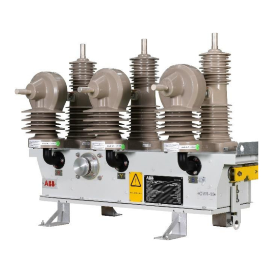
RECLOSER IGH VOLTAGE ASSEMBLY The high-voltage assembly of the OVR-15, 27 & 38 consists of three poles mounted onto a common housing. Each of the poles is a separate assembly comprised of a vacuum interrupter assembled in a HCEP molded pole. All the three poles are gang operated by a single coil magnetic actuator through a common operating shaft. -
Page 17: Recloser Pole And Current & Voltage Sensor
The current (I) sensing is by current transformer (CT) and voltage (U) sensing is by a voltage divider. The sensor secondary connections are bought out of the pole via shielded cables. In OVR-15 & 27, option is available for single OR dual voltage sensing per pole. Figure-6.1: OVR-15 Pole with single voltage sensor Figure-6.2: OVR-15 Pole with dual voltage sensor... -
Page 18: Single Coil Magnetic Actuator
Recloser can be mechanically opened (not manual close possible) by pulling this handle from ground level with a standard hook stick (not in ABB’s scope). Please refer the clause “mechanical opening” under the “operation” section for more information. -
Page 19: Standard Production Tests
TANDARD PRODUCTION TESTS Routine tests are carried out on OVR-15, 27 & 38 with HV units connected with its dedicated LV units . The standard factory production tests include: 1. Verification of wiring as per approved wiring diagram. 2. Electrical operation: a. -
Page 20: Vacuum Test Procedure
40 kV AC (80% of 50kV) for OVR-15, 45 kV AC (80% of 60kV) for OVR-27 and 56 kV AC (80% of 70kV) for OVR-38 across the open contacts. -
Page 21: Pole Mounting
OR live conductors. 21 | P a g e Instruction Manual for HV Unit of OVR-15, 27 & 38... - Page 22 The heights of pole structure and recloser location shown are for reference Note purpose only. These depend on user’s installation. XXX: To be decided by the user. Supply of pole is not in ABB’s scope. 22 | P a g e Instruction Manual for HV Unit of OVR-15, 27 & 38...
- Page 23 Ohm (1 Ω). Grounding Pad Figure -13 : Provisions for Grounding Connections on HV cabinet 23 | P a g e Instruction Manual for HV Unit of OVR-15, 27 & 38...
- Page 24 Figure-14 : Grounding connections proposed for OVR-15,27,38 Pole Mounted arrangement The grounding cables used shall be same for all components Note RRESTER PROTECTION Surge arresters can be connected on both HV (source and load) sides of the recloser. It is recommended that the arrester grounds are connected to the recloser ground and continued to the pole ground.
- Page 25 OVR terminal H1 & H2 via suitable terminal connector/clamp. Both these terminals are silver plated copper. The fasteners use for connectors must be torqued between 50 to 60 NM (442 to 531 inch lbf). Respective H1 and H2 terminals Line connections for OVR-15 and OVR-27/38 are shown in the below pictures General convention proposed for power connection is H1 terminal should be on the source side and H2 on load side.
- Page 26 Securely tighten terminals and ground connections. Check control cable is properly connected, routed and secured. Ensure both the HV & LV cabinets are grounded as mentioned in this manual. 26 | P a g e Instruction Manual for HV Unit of OVR-15, 27 & 38...
-
Page 27: Recloser Operation
SCADA via communication, with RER615 relay in REMOTE mode. Due to safety concerns, OVR-15, 27 & 38 is not allowed to manually be closed and does not have any separate provision to close the recloser manually using any hook stick. -
Page 28: Inspection And Maintenance
Figure-18 : Manual Opening NSPECTION AND MAINTENANCE The OVR-15, 27 & 38 will require minimal maintenance if handled properly. Frequency of operation and local environmental conditions should be considered when determining maintenance schedule. To a large extent, the safety and successful functioning of any apparatus or system connected with the recloser depends on the proper installation, commissioning, programming and configuration of the unit. - Page 29 On the basis of the result obtained during the periodic inspection, it is possible to set the optimal time interval for carrying out maintenance work. 29 | P a g e Instruction Manual for HV Unit of OVR-15, 27 & 38...
-
Page 30: Typical Rating Plate Details
16 kA 3sec Short Circuit Making Current (Peak) 31.25 kA pk 31.25 kA pk 41.6 kA pk Mass (Approx.) Instruction Manual 1VYN401790-021 1VYN401790-049 1VYN401390-078 30 | P a g e Instruction Manual for HV Unit of OVR-15, 27 & 38... -
Page 31: Ga Of Hv Cabinet Drawings
CABINET DRAWINGS 11.1.1 OVR-15 HV Cabinet General Arrangement: 31 | P a g e Instruction Manual for HV Unit of OVR-15, 27 & 38... -
Page 32: Ovr-27 Hv Cabinet With Single Voltage Sensing General Arrangement
11.1.2 OVR-27 HV Cabinet with Single Voltage Sensing General Arrangement: 32 | P a g e Instruction Manual for HV Unit of OVR-15, 27 & 38... -
Page 33: Ovr-27 Hv Cabinet With Double Voltage Sensing General Arrangement
11.1.3 OVR-27 HV Cabinet with Double Voltage Sensing General Arrangement: 33 | P a g e Instruction Manual for HV Unit of OVR-15, 27 & 38... -
Page 34: Ovr-38 Hv Cabinet General Arrangement
11.1.4 OVR-38 HV Cabinet General Arrangement: 34 | P a g e Instruction Manual for HV Unit of OVR-15, 27 & 38... -
Page 35: Recommended Spare Parts
Apart from above we recommend to regularly monitor battery health (since, batteries have limited lifetime depending on environmental conditions), and procure them in advance whenever, they are nearing their end of life. 35 | P a g e Instruction Manual for HV Unit of OVR-15, 27 & 38... - Page 36 Customer Service 1-800-929-7947 Customer.Service.Group@us.abb.com Customer support: 18004200707 Customer support: ppmvsupport@in.abb.com customer.service.group@in.abb.com ABB de México S.A. de C.V. ABB Argentina S.A.U. Av. Central 310 Parque Logístico CP. 78395 San Luis Norberto López 3600 Potosí, SLP, México B1805ABT, El Jagüel, Buenos Aires...
Need help?
Do you have a question about the OVR-15 and is the answer not in the manual?
Questions and answers