Table of Contents
Advertisement
Quick Links
®
USE MANUAL and SPARE PARTS
IMPORTANT DO NOT DESTROY !
Read carefully this manual before using the tool and
respect the security norms herewith enclosed.
Via Foresto 42 - 31058 SUSEGANA TV ITALY
80.16 ROC
cod. 11560ROC
5 4 8 7 7 0 6
11560ROC_8016ROC_5 051118 IV
Tel.0438455318 Fax 0438455530
E-mail: omer@omer.it
INTRODUCTION:
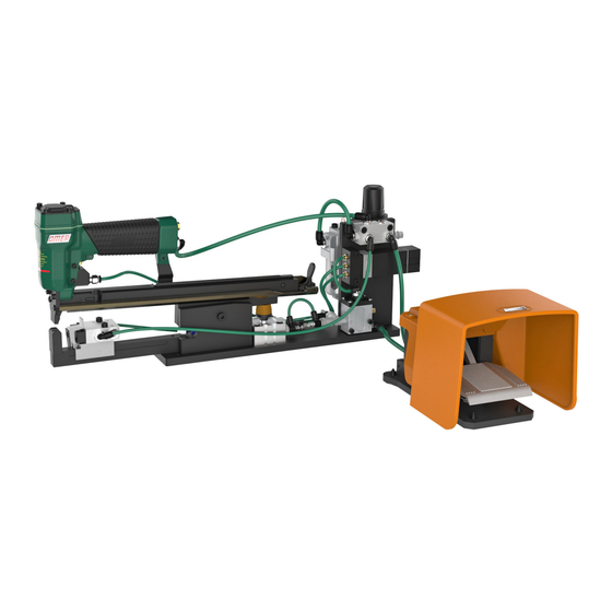
The bench-mounted stapler ROC is the optimal solution for fixing blisters, paper or
plastic bags, boxes, displaying cards, etc.
Features:
• Possibility to be easily fixed upon working surface
•Pneumatic system complete with FRL unit & manometer for a correct power
supply
• Pedal activated mode
•Working pressure: 5,5 ÷ 6,5 bar ( 80÷ 95 PSI )
• Top loading
• Magazine capacity: 2 strips
• Applicable sizes: 6 to 16mm
• Easy jam-clearing
• Easily replaceable pneumatic tool units (with units suitable for different fastener
series, i.e. 3G, 64, 80, 50, 65, 40, 4097)
• Possible adjustements:
MADE
IN
ITALY
www.omer.it
- Clinching depth
- Front side opening
- Clinching speed
- Fire delay
Advertisement
Table of Contents

Subscribe to Our Youtube Channel
Related Manuals for Omer 80.16 ROC


Summary of Contents for Omer 80.16 ROC
- Page 1 ® INTRODUCTION: The bench-mounted stapler ROC is the optimal solution for fixing blisters, paper or 80.16 ROC plastic bags, boxes, displaying cards, etc. Features: cod. 11560ROC • Possibility to be easily fixed upon working surface •Pneumatic system complete with FRL unit & manometer for a correct power supply •...
- Page 2 Easy jam-clearing trigger Manometer Silenced rear exhaust Automated hold down Filter/reducer/lubricator unit Fire delaying regulator opening mechanism 2 strips capacity magazine Distributor Clinching speed regulator (opening) Airplug connector Timer Plate for bench-mounting Control lever for contact activation Pneumatic valve Anvil Front side opening adjustment Clinching speed regulator Adjustable spacer...
-
Page 3: Table Of Contents
- Firing ........... 13 - Adjustment of working cycle....14 Loading ........................15 Jam-clearing ........................ 16 Spare parts for 80.16 ROC-C stapler ................17 Spare parts for 80.16 ROC ..................18 Pneumatic diagram ..................... 19 Accessories – O-Rings ....................20 Spare parts list ...................... -
Page 4: Conformity Declaration
INTRODUCTION In order to assure high reliability, OMER has made a careful choice of the materials and components to be used in the manufacturing process of the tool and has tested it before delivery. Proper performance of the tacker in time also depends on its correct use and on adequate servicing according to the instructions contained in this manual. -
Page 5: Section B Compressed Air Supply System
OMER spa does not answer for damage to the gun due to the use of staples or nails of types not suitable for the model. -
Page 6: Section D Information Regarding Maintenance And Repair
To do so, unscrew the head screws with the hex spanner supplied, open the gun and remove the different components. Check carefully the state of wear of the O-rings and of the rubber parts. Replace the worn parts with OMER original spare parts. -
Page 7: Technical Data
Technical data Suitable staple series : Stapling results 98.06 (standard supplied) 0,65x0,95 staple 1/4" 5/8" 11,4 Crown: .500” (1/2“) Thickness: .025" Width: .037" Gauge: 6÷16 Usable lenghts mm 1/4"÷5/8" Usable lengths inch Magazine capacity No. of fasteners 5,5÷6,5 Working pressure bar Working pressure psi 80÷95 0,58... - Page 8 Technical data *all sizes are shown in mm Max 10 15,5 Min 0,5 27,5 115,5 Max 18 160,5 - 9 -...
-
Page 9: Operating Mode
Operating mode Tool operating : 1 - Press pedal to activate the devices. 2 - Insert the material to be fastened by pressing against the control lever wich will activate the tool. Before using the unit make sure all necessary adjustments for a correct and safe usage have been performed. -
Page 10: Front Side Opening
Adjustment of front side opening A front side opening adjustment must be carried out to allow an easy insertion of the material to be fastened. max 18 mm 2 mm 1 - Press the stapler head and keep this position to gain access to the pneumatic cylinder and bumper. -
Page 11: Clinching Depth
Clinching depth adjustment To avoid flattening/damaging the material to be fastened it is possible to set the clinching depth by adjusting the end-run screw. Disconnect the air before proceeding with the adjustment. max 10 mm min 0,5 mm 1 - Loosen the nut which stops the end-run screw. 2 - Screw or unscrew the end-run screw to adjust the clinching depth. -
Page 12: Clinching Speed
Fire delay adjustment Fire delay adjustment is the more necessary the wider is the front opening on the tool, since you must give time to the stapler to block the material before firing. delays firing anticipates firing Clinching speed adjustment This adjustment allows you to set the most comfortable working speed. -
Page 13: Adjustment Of Working Cycle
Adjustment of working cycle This adjustment fixes the lengt of the working cycle, which starts with the activation of the control lever and stops by releasing the fastened material Working cycle time is adjusted by acting on timer as follow: The best performance of the tool is achieved by syncronizing clinching speed, firing delay and tool return time 1 - Use a screw driver to rotate the selector marked with an... -
Page 14: Loading
Loading DO NOT press pedal while loading, to avoid activating the device 1 - Pull the pusher backwards and lock it at the stop position at the rear of the tool, this will open the movable hold down 2 - Load staples 3 - Release the slider - 15 -... -
Page 15: Jam-Clearing
Jam-clearing In case of jamming, proceed as follows: 1 - Pull the pusher all the way back and lock it. 2 - Remove the staples from the magazine. 3 - Open the slider closing trigger. 4 - Pull the slider all the way back by acting on the pusher and holding it in such a position. 5 - Pull the jammed staple out from the firing channel. -
Page 16: Spare Parts
05.12.2 64.05 98.02 98.06 08.00.1Z 08.16.6Z 80.16 ROC-C c o d . 2 1 5 6 0 R O C - C 80.16 ROP Upgrade c o d . 1 1 5 6 0 R O P Number - 17 -... - Page 17 ø 05.25 17.37.7 06.19 17.31.8 17.37.2 05.20 06.00.3 B(V) 18.02 Ø 18.50 17.38 17.34.8 98.01 17.31.8 18.34.1 98.05.2 05.25 05.20 05.20 80.16 ROC Upgrade c o d . 1 1 5 6 0 R O C Number - 18 -...
-
Page 18: Pneumatic Diagram
Pneumatic diagram 5,5 ÷ 6,5 bar B(V) Ø4 Ø4 Ø4 Ø4 A(C) B(V) Ø4 Ø6 Ø6 R P S Ø6 5,5 ÷ 6,5 bar - 19 -... -
Page 19: Spare Parts List
00.06 00.04 18.21 Manometro Manometer Boccetta olio Oiler 80.16 ROC Upgrade 80.16 ROC Upgrade c o d . 1 1 5 6 0 R O C c o d . 1 1 5 6 0 R O C Number Number... -
Page 20: Notes
Notes - 22 -...
Need help?
Do you have a question about the 80.16 ROC and is the answer not in the manual?
Questions and answers