Table of Contents
Advertisement
Quick Links
ARI.D23.4.IOM.EN01.0721
Installation, Operation & Maintenance
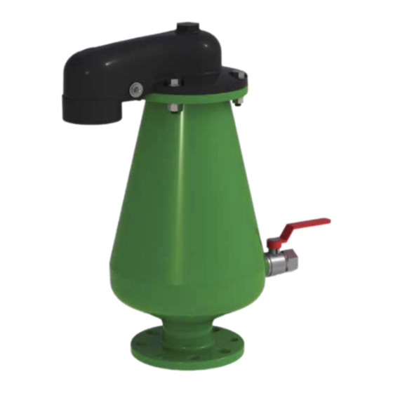
D-23 4"
Combination Air Valve
The following is a step by step narrated description of the A.R.I. D-23 industrial combination air valve
installation, operation and maintenance processes.
A.R.I. D-23 air valve is designed for systems that operate within the pressure and temperature framework
of the model's specifications table. Please consult Aquestia for products designed for other hazardous
liquids systems.
Advertisement
Table of Contents

Related Manuals for Aquestia A.R.I. D-23


Summary of Contents for Aquestia A.R.I. D-23
- Page 1 D-23 4" Combination Air Valve The following is a step by step narrated description of the A.R.I. D-23 industrial combination air valve installation, operation and maintenance processes. A.R.I. D-23 air valve is designed for systems that operate within the pressure and temperature framework of the model's specifications table.
-
Page 2: Table Of Contents
Except as provided herein and to the full extent permitted by law, Aquestia shall not be responsible and/or liable for direct, special, incidental or consequential damages or loss resulting from any breach of the above or under any other legal theory. -
Page 3: Safety Instructions
10. Use the product only for its intended use as designed by Aquestia. Any misuse of the product may lead to undesired damages and may affect your warranty coverage. Please consult with Aquestia prior to any non-regular use of this product and make no change or modification to the product without a prior written consent to be provided by Aquestia at Aquestia's sole discretion. - Page 4 In order to achieve maximum performance and smooth operation of the product, it is crucial to perform the startup and first operation procedures exactly as described in this manual. In cases where formal commissioning procedure is required, it should be done by an authorized Aquestia technician prior to the first operation of the product.
-
Page 5: Installation
IOM A . R . I . D-23 2. Installation Important: Before performing any work on the air valve make sure that all workers on site are familiar with the safety instructions and the relevant local and general safety instructions and work regulations. 2.1. -
Page 6: Installation Instructions
IOM A . R . I . D-23 2.2. Conventions and Measurements Isolation valve This paragraph presents and explains the terms and measurements used for the Installation process. D = Diameter of pipeline d = diameter of riser H = Height of riser on the pipeline (measured from crown of pipeline) •... -
Page 7: Operation
IOM A . R . I . D-23 3. Operation When the system is charged and the pipeline begins to fill, the water flowing in the pipeline enters into the combination air valve, raising the air/ vacuum and air release floats to their sealing position. During filling, air is discharged mainly through the air/ vacuum orifice as well as small amounts of air released through the air release orifice. -
Page 8: Periodic Maintenance
IOM A . R . I . D-23 5. Periodic Maintenance Please note that the periodic maintenance of the air valve is an integral part of the proper pipeline maintenance regime; it should be maintained at least once a year in accordance with the quality and composition of the fluid in the system. Important: Before performing any work on the air valve, make sure that all workers on site are familiar with the safety instructions as appear in chapter 1 of this document and with all the relevant local and general safety instructions, standards and work regulations. - Page 9 IOM A . R . I . D-23 5.2.2 Removal of the Sealing Assembly • Using the two 19mm combination spanners, open and remove the four Bolts, Nuts and Washers [1] • Store the four Bolts, Nuts and Washers in an accessible area [2] •...
- Page 10 IOM A . R . I . D-23 5.2.4. Assembly and Testing for Leaks • Insert the Cover & Float Assembly into the main valve Body [1]. • Insert the four Bolts, Nuts and Washers [2] . Using the two 19mm combination spanners, tighten using the crossover method [3]. •...
- Page 11 IOM A . R . I . D-23 5.3. Second Stage Maintenance Perform if the first stage doesn't solve the leak, if one of the seals or inner parts need replacement or for periodic maintenance to thoroughly clean the valve. 5.3.1.
- Page 12 IOM A . R . I . D-23 2- Remove the Spray Guard • Pull open the Spray Guard by the slit and remove it from the assembly rod [1] [2] 3- Remove the Seal & Float Assembly from the Cover •...
- Page 13 IOM A . R . I . D-23 5.3.3. Maintenance 1- Cleaning Wash and clean all disassembled parts, including the Float and Seal Assembly, Spray Guard, Body and Cover under clean running water to remove all dirt and grime. 2- Replacing the Automatic Air Release and Air & Vacuum (Kinetic) Seals 2.1 Opening the Seal Assembly •...
- Page 14 IOM A . R . I . D-23 2.2 Replacing the Automatic Air Release Rolling Seal • To replace the Air Release Rolling Seal [1] pull the seal out of the slots from both ends and discard [2] [3] • Dip both ends of the new replacement Rolling Seal in the liquid soap [4] •...
- Page 15 IOM A . R . I . D-23...
- Page 16 IOM A . R . I . D-23 2.3 Replacing the Air & Vacuum (Kinetic) Seal • Hold the Air & Vacuum Seal [1] and pull it off the lower section of the Seal housing [2], [3] • Place the new Seal on the Seal housing [4] and press down until it fits securely and tightly on the housing [5]...
- Page 17 IOM A . R . I . D-23 2.4 Closing the Seal Assembly • Align the 4 holes of the top and bottom section of the Seal Assembly housing [1] and close one section against the other • Insert the 4 screws into the Seal Assembly housing [3] and screw them tightly in place [4], [5].
- Page 18 IOM A . R . I . D-23 5.3.4. Assembly 1- Cover Assembly • Examine the Cover O-ring for cracks or tears [1]. Replace, if necessary. •. Insert the Disk Arm Assembly, together with the attached Seal and Float Assembly into the bottom opening of the Cover [2], [3] •...
- Page 19 IOM A . R . I . D-23 2- Insert the Cover and Seal & Float Assembly • Pull open the Spray Guard by the slit and slide it over the assembly rod [1] [2] • Lift and insert the Float and Seal Assembly into the Body [3] •...
-
Page 20: Assembly Bom Table And Drawing
IOM A . R . I . D-23 6. Assembly BOM Table and Drawing No. Part name QTY. Threaded Plug Cover Bolt Washer Bushing Domed Nut Disk Arm Air & Vacuum Seal Seat Air & Vacuum Seal Air Release Seal Air Release Seal Seat Air &...
Need help?
Do you have a question about the A.R.I. D-23 and is the answer not in the manual?
Questions and answers