Sign In
Upload
Download
Table of Contents
Contents
Add to my manuals
Delete from my manuals
Share
URL of this page:
HTML Link:
Bookmark this page
Add
Manual will be automatically added to "My Manuals"
Print this page
×
Bookmark added
×
Added to my manuals
Manuals
Brands
Sinclair Manuals
Air Conditioner
BOAT ASB-05A
User manual
Sinclair BOAT ASB-05A User Manual
Hide thumbs
1
2
3
4
Table Of Contents
5
6
7
8
9
10
11
12
13
14
15
16
17
18
19
20
21
22
23
24
25
26
27
28
29
30
31
32
33
34
35
36
page
of
36
Go
/
36
Contents
Table of Contents
Troubleshooting
Bookmarks
Table of Contents
Table of Contents
Safety Precautions
Introduction
Overview
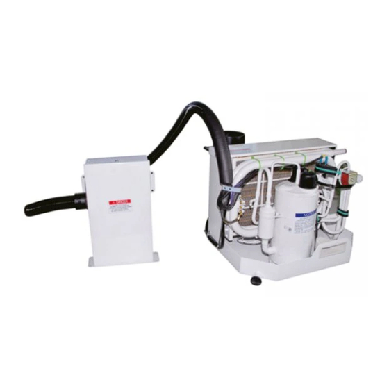
Outline Drawing
How It Works
Outline Dimensions
Installation
Unpacking and Inspection
Safety Considerations
The Size of Sealed Room
Placement of System
Condensate Drains
Blower Assembly
Mounting Brackets
Supply & Return Air Grilles and Transition Boxes
Ducting
Seawater Pump and Plumbing
Electrical Connections
Manual Controller Installation
Electric Box Installation
Installation Checklist (Review Prior to Installation)
Wiring Requirements
Operation
Manual Controller Operation
Power ON/OFF
FAN Control
Temperature Setting
Mode Setting
Display Fahrenheit or Centigrade
Error Codes
Key Lock
Checking Voltage Function
Starting Interval Setting
Auto-Off Function of the Manual Controller
Accessories
Remote Controller Operation
Control Panel of the Wireless Remote Controller
Introduction for Special Function
Replacement of Batteries
Troubleshooting
Maintenance
Reversing Valves
Seawater Strainer
Blowers
Condenser Coil Cleaning
Return Air Filters
Winterization
Limited Warranty
Technical Assistance
Technical Support
Advertisement
Quick Links
Download this manual
EN
USER'S MANUAL
BOAT SERIES
ASB-05A, ASB-09A, ASB-12A,
ASB-16A, ASB-20A, ASB-24A
Table of
Contents
Previous
Page
Next
Page
1
2
3
4
5
Advertisement
Table of Contents
Need help?
Do you have a question about the BOAT ASB-05A and is the answer not in the manual?
Ask a question
Questions and answers
Related Manuals for Sinclair BOAT ASB-05A
Air Conditioner Sinclair BOAT Series Service Manual
(43 pages)
Air Conditioner Sinclair BOAT ASB-09A User Manual
(36 pages)
Air Conditioner Sinclair BOAT ASB-24A User Manual
(36 pages)
Air Conditioner Sinclair ASH-18AK Series Service Manual
King series (43 pages)
Air Conditioner Sinclair ASH-09AIE2 Service Manual
Element serie (86 pages)
Air Conditioner Sinclair ASW-09BI User Manual
Window type air condition (28 pages)
Air Conditioner Sinclair ASF-60AN Service Manual
On/off series (96 pages)
Air Conditioner Sinclair ASF-60A User Manual
Floor & ceiling series (18 pages)
Air Conditioner Sinclair ASH-09CS Owner's Manual
(30 pages)
Air Conditioner Sinclair ASH-24AIM PT User Manual
(36 pages)
Air Conditioner Sinclair ASDH-96AI Service Manual
High static pressure duct serie (88 pages)
Air Conditioner Sinclair Uni Split Duct series User Manual
(28 pages)
Air Conditioner Sinclair ASD BI Series User Manual
Uni split duct series (35 pages)
Air Conditioner Sinclair ASC-BI Series Service Manual
(226 pages)
Air Conditioner Sinclair Spectrum Series User Manual
(32 pages)
Air Conditioner Sinclair TOWER Series Installation Manual
(47 pages)
This manual is also suitable for:
Boat series
Boat asb-09a
Boat asb-12a
Boat asb-16a
Boat asb-20a
Boat asb-24a
Table of Contents
Print
Rename the bookmark
Delete bookmark?
Delete from my manuals?
Login
Sign In
OR
Sign in with Facebook
Sign in with Google
Upload manual
Upload from disk
Upload from URL


Need help?
Do you have a question about the BOAT ASB-05A and is the answer not in the manual?
Questions and answers