
Subscribe to Our Youtube Channel
Related Manuals for Sorel Circulation Controller CC


Summary of Contents for Sorel Circulation Controller CC
- Page 1 Circulation Controller CC Installation and operating instructions Read carefully before installation, commissioning and operation...
-
Page 2: Table Of Contents
Content Safty instructions Protective functions A.1. EC declaration of conformity 5.1. Seizing protection A.2. General instructions 5.6. Anti-Legionella A.3. Explanation of symbols A.4. Changes to the unit Special functions A.5. Warranty and liability 6.2. Signal V1 6.2.1. Type of signal Description of controller 6.2.2. Profile B.1. Specifications... -
Page 3: Safty Instructions
Safety instructions A.1. - EC declaration of conformity By affi xing the CE mark to the unit the manufacturer declares that the CC conforms to the following relevant safety regulations: • EC low voltage directive 2006/95/EC • EC electromagnetic compatibility directive 2004/108/EC Conformity has been verifi ed and the corresponding documentation and the EC declaration of conformity are kept on fi le by the manufacturer. A.2. - General instructions It is essential that you read this! These installation and operating instructions contain basic instructions and important information regarding safety, installation, commissioning, maintenance and the optimal use of the unit. -
Page 4: Changes To The Unit
Safety instructions A.4. - Changes to the unit Changes to the unit can compromise the safety and function of the unit or the entire system. Danger • Changes, additions to or conversion of the unit are not permitted without the written permission from the manufacturer •... -
Page 5: Description Of Controller
Description of controller B.1. - Specifications Mains voltage 230 AC +/- 10 % Mains frequency 50 - 60 Hz Power consumption ~ 1.5VA Internal fuse 2A slow blow 250V Protection category IP40 Protection class Overvoltage Category Degree of Pollution Category mechanical relay 460VA for AC1 / 460W for AC3 0-10V output, tolerance 10%, 10 k Ω load or PWM output freq. 1 kHz, level 10 V... -
Page 6: About The Controller
Description of controller B.5. - About the controller The Circulation Controller CC facilitates effi cient use and function control of your solar or heating system. The device is impressive most of all for its functionality and simple, self-explanatory operation. For each step in the input process the individual entry keys are assigned to appropriate functions and explained. The controller menu contains headwords for the measured values and settings, as well as help texts or clearly-struc- tured graphics. -
Page 7: Hydraulic Variants
Description of controller B.6. - Hydraulic variants The following illustrations should be viewed only as schematic dia- grams showing the respective hydraulic systems, and do not claim to be complete. The controller does not replace safety devices under any circumstances. Depending on the specifi c application, additional system Caution components and safety components may be mandatory, such as check valves, non-return valves, safety temperature limiters, scalding protec-... -
Page 8: Installation
Installation Wall installation Install the controller only in dry areas and under the ambient conditions de- scribed under 2.1 “Specifi cations”. Carry out the following steps: Caution 1.Unscrew cover screw completely C.1.1 2.Carefully pull upper part of housing from lower part. 3.Set upper part of housing aside, being sure not to touch the electronics when doing so. -
Page 9: Electrical Connection
Installation Electrical connection Before working on the unit, switch off the power supply and secure it against being switched on again! Check for the absence of power! Electrical connections may only be made by a specialist and in Danger compliance with the applicable regulations. Do not use the controller if the housing shows visible damage. Low-voltage cables such as temperature sensor cables must be routed separately from mains voltage cables. - Page 10 Installation 5. Connect the female connector block ‘s C.2.1.c clamp connections as described in the terminal connection plans. When using stranded cables, use a small screw driv- er and push the orange buttons while inserting (see fig. C.2.1.c). When using solid cable or end splice, just push the cables in (see fig. C.2.1.c). 6. Plug Female connectors into onboard headers.
-
Page 11: Installing The Temperature Sensors
Installation Installing the temperature sensors The controller operates with Pt1000 temperature sensors which are accurate to the degree, thus ensuring optimal control of system functions. Position the sensor precisely in the area to be measured! Only use immersion, pipe-mounted or fl at-mounted sensors suitable for the specifi c area of application with the appropriate permissible Caution temperature range. -
Page 12: Terminal Connection Diagrams
Installation Terminal connection diagrams 230VAC Low voltage max. 12V Mains voltages Danger Caution Low voltage max. 12VAC/DC connection Mains voltages 230 VAC 50-60Hz Terminal: Connection for: Terminal: Connection for: S1 (2x) Sensor 1 storage top Mains phase conductor L S2 (2x) FSensor 1 storage center Mains neutral conductor N (optional) -
Page 13: Operation
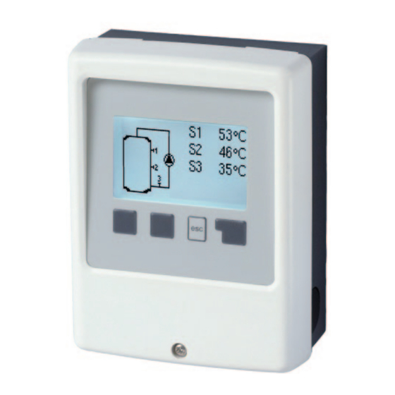
Operation Display and Input The display (1), with its extensive text and graphics mode, is almost self-explanatory, allowing easy operation of the controller. Entries are made using four keys (2+3), which are assigned to different functions depending on the situation. The “esc” key (2) is used to cancel an entry or to exit a menu. If applicable there will be a request for confirmation as to whether the changes which have been made should be saved. -
Page 14: Parametrisation
Operation Parametrisation The fi rst time the controller is turned on and after the language and time are set, a query appears as to whether you want to parametrise the controller using the commissioning help or not. The commis- sioning help can also be terminated or called up again at any time in the special functions menu. -
Page 15: Menu Sequence And Menu Structure
Operation Menu sequence and menu structure The graphics or overview mode appears when no key has been pressed for 2 min- utes, or when the main menu is exited by pressing “esc“. Pressing a key in graphics or overview mode takes you directly to the main menu. The following menu items are then avail- able for selection there: Current temperature values with 1. -
Page 16: Measurement Values
Measurement values 1. - Measurement values The menu “1. Measurement values” serves to display the currently measured temperatures. The menu is closed by pressing “esc” or selecting “Exit measurements ”. Selecting “Details” leads to a brief help text explaining the measurement values. Selecting “Overview” or “esc” exits the Info mode. If “Error” appears on the display instead of the measurement value, then there may be a defective or incorrect temperature sensor. If the cables are too long or the sensors are not placed optimally, the result may be small deviations in the measurement values. -
Page 17: Statistics
Statistics 2. - Statistics The menu “2. Statistics” is used for function control and long-term monitoring of the system. The menu is closed by pressing “esc” or selecting “Exit statistics”. For analysis of the system data it is essential for the time to be set accurately on the controller. Please note that the clock continues for about 24 hours if the mains voltage is interrupted, and must be reset afterwards. -
Page 18: Operating Modes
Operating modes 3. - Operating modes In menu “3. Operating modes” the con- troller can either be placed in automatic mode, switched off , or placed in a manual operating mode. The menu is closed by pressing “esc” or selecting “Exit operating modes”. 3.1. - Automatic Automatic mode is the normal operating mode of the controller. Only automatic mode provides proper controller function taking into account the current temperatures and the parameters that have been set! After an interruption of the mains voltage the con- troller automatically returns to the last operating mode selected! 3.2. -
Page 19: Settings
Settings 4. - Settings The necessary basic settings required for the control function are made in menu “4. Settings”. This does not under any circum- stances replace the safety facilities to be provided by the customer! Caution The menu is closed by pressing “esc” or selecting “Exit settings”. Various settings can be made depending on the selection of hydraulic variant. The following pages contain generally valid descriptions for the settings. -
Page 20: Protective Functions
Protective functions 5. - Protective functions Menu “5. Protective functions” can be used to activate and set various protective func- tions. This does not under any circum- stances replace the safety facilities to be provided by the customer! Caution The menu is closed by pressing “esc” or select- ing “Exit settings”. 5.1. - Seizing protection If the Seizing protection is activated, then the controller switches the associated pump and/or valve on every day at 12:00 or on Sundays at 12:00 for 5 seconds in order to prevent the pump and/or valve from sticking after an extended stationary period. -
Page 21: Special Functions
Special functions 6. - Special functions Menu “6. Special functions” is used to set basic items and expanded functions. Other than the time all settings may only be made by a specialist. Caution The menu is closed by pressing “esc” or selecting “Exit special functions”. Menu enumerations may vary according to CC version used. Caution 6.2. - Signal V1 This menu contains the settings for 0-10V or PWM pump. -
Page 22: Output Signal
Special functions 6.2.3. - Output Signal This menu determines the type of pump used: Solar pumps perform at their highest power when the signal is also maxed, heating pump on the other hand are set to high- est power when the control signal is at the lowest. Solar = normal, heating = Inverted. Settings range: Normal, Inverted / Default setting: Normal When Output signal PWM is selected: / When Output signal 0-10V is selected: 6.2.4. - Page 23 Special functions 7.2.8.b Technical data PWM and 0-10V Technical data PWM: PWM: 20% to 100%, 1kHz Designed for a load of 10K Ohm Technical data 0-10V: 10V = 100% Speed 0-10V: 2V to 10V (20% to 100%) 5V = 50% Speed Designed for a load of 10K Ohm. 2V = 20% Speed 0V = Off...
-
Page 24: Speed Control
Special functions 6.3. - Speed control If the speed control is activated, the makes it possible to vary the speed of standard pumps at relay by means of special internal electronics. This function should only be activated by a specialist. Depending on the pump and pump stage used, the minimum speed should not be set too low, because otherwise the pump or the system may be damaged. -
Page 25: Purging Time
Special functions 6.3.2. - Purging time During this time period, the pump is running with full speed (100%) to ensure trouble- free startup. After this time has passed, the pump is set to speed control and is set to max. speed or min speed, depending on the speed control variant. Purging time can not be applied with PWM or 0-10V output. -
Page 26: Time And Date
Special functions 6.4. - Time and Date This menu is used to set the current time and date. For analysis of the system data it is essential for the time to be set accu- rately on the controller. Please note that the clock has a 24 hour battery and must be reset if the power was cut for a longer period. Caution 6.5. -
Page 27: Menu Lock
Menu lock 7. - Menu lock Menu “7. Menu lock” can be used to secure the controller against unintentional changing of the set values. The menu is closed by pressing “esc” or select- ing “Exit menu lock”. The menus listed below remain completely accessible despite the menu lock being activated, and can be used to make adjustments if necessary: Measurement values Analysis Display mode 7.2. Time & date 8. Menu lock Service values To lock the other menus, select “Menu lock on”. To enable the menus again, select “Menu lock off”. -
Page 28: Service Values
Service values 8. - Service values The menu “8. Service values” can be used for remote diagnosis by a specialist or the manufacturer in the event of an error, etc. Enter the values at the time when the error occurs e.g. in the table. Caution The menu can be closed at any time by pressing “esc”. -
Page 29: Malfunctions With Error Messages
Malfunctions Malfunctions with error messages If the controller detects a malfunction, the red light fl ashes and the warning symbol also appears in the display. If the error is no longer present, the warning symbol changes to an info symbol and the red Info and warnings light no longer fl... -
Page 30: Replacing The Fuse
Fuse Replacing the fuse Repairs and maintenance may only be performed by a specialist. Before working on the unit, switch off the power supply and secure it against being switched on again! Check for the absence of power! Danger Only use the supplied spare fuse or a fuse of the same design with the following specifi cations: T2A 250V Danger Z.2.1 Fuse If the mains voltage is switched on and the controller still does not function or display anything, then the internal device fuse may be defective. -
Page 31: Maintenance
Maintenance Z.3. Maintenance In the course of the general annual maintenance of your heating system you should also have the functions of the controller checked by a specialist and have the settings optimised if necessary. Caution Performing maintenance: • Check the date and time (see „7.4. - Time and Date“ on page 26 ) • Assess/check plausibility of analyses (see „2. - Statistics“ on page 17) • Check the message log (see „2.5. - Message log“ on page 17) • Verify/check plausibility of the current measurement values (see „1. - Measurement values“ on page 16) • Check the switch outputs/consumers in manual mode (see „4.2. - Manual“ on page 18) •... - Page 32 Although these instructions have been created with the greatest possible care, the possibility of incorrect or incomplete information cannot be excluded. Subject as a basic principle to errors and technical changes. Your specialist dealer: Manufacturer: SOREL GmbH Mikroelektronik Jahnstr. 36 D - 45549 Sprockhövel Tel. +49 (0)2339 6024 Fax +49 (0)2339 6025 www.sorel.de info@sorel.de...
Need help?
Do you have a question about the Circulation Controller CC and is the answer not in the manual?
Questions and answers