
Related Manuals for Tutco SureHeat Jet


Summary of Contents for Tutco SureHeat Jet
- Page 1 Jet Air Heater FOR SAFETY AND LONG HEATER LIFE, CAREFULLY READ THIS MANUAL BEFORE USE.
-
Page 2: Specifications
THANK YOU FOR CHOOSING THE JET AIR HEATER TUTCO JET AIR HEATER The Jet provides a compact, efficient heater for heating air or inert gases to 1400°F (760°C) in either a 3kW or 8kW, 240V 1PH unit. Two (2) type “K” thermocouples with a convenient terminal block are included for ease of wiring. -
Page 3: Electrical Shock Hazard
WARNINGS! TUTCO SureHeat Process Air Heaters contain high watt-density elements and must be controlled carefully to prevent element failure. IMPORTANT: Be sure to read and understand this operating manual before turning the system ON. Follow all checklists shown in the manual. Failure to do so can cause a heater failure and may void warranty. - Page 4 Operate at safe voltages as shown on the Performance Curves (see page 12). Excess voltage will cause premature failure. (See Proper Temperature Controller Setup on Page 8 for details.) Using the Jet heater with the Jet Control Panel provides loss of airflow protection if wired properly.
- Page 5 HEATER MODEL AND PARTS LIST Part Maximum Maximum Maximum Maximum Temperature Number Wattage Voltage Amperage F074718 3000 240 – 1Ø 12.5 1400ºF / 760ºC F074719 8000 240 – 1Ø 33.3 1400ºF / 760ºC * Follow applicable electrical codes during installation...
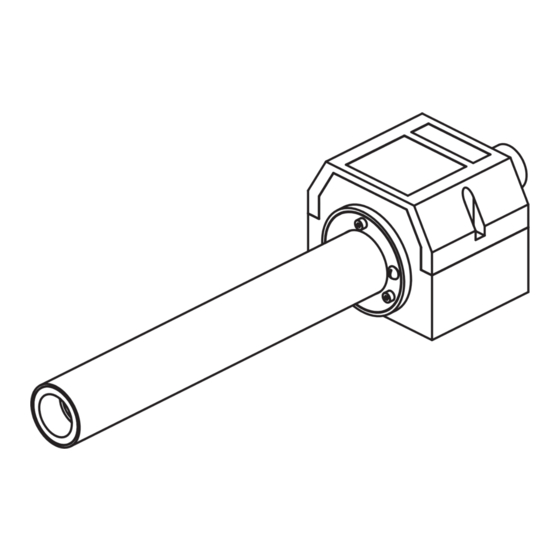
- Page 6 DIMENSIONS/MOUNTING NOTE: The inlet side of the heater is located where the leads/power feedthrus come out of the housing. Failure to install the heater in its proper orientation can result in heater damage and is not covered under the manufacturer’s warranty. 14.92 [378.9] 11.42 [290.1] .69 [17.5]...
- Page 7 JET CONTROL PANEL DIMENSIONS 8.50 [215.9] #10-32 TH’D 6.00 [152.4] 4-PLCS TEMP POWER 10.50 9.12 [266.7] [231.6] LINE HEATER 6.29 [159.8] 1.06 [26.9] 1.60 [40.6] 1.74 [4.44] 8.25 [209.6] [22.4] 2.50 [63.5]...
- Page 8 (0% output) before the contactor is engaged and immediately applying full power. 4 Use proper closed loop control (PID) settings. TUTCO SureHeat typically uses the following PID; Proportional (P), Integral (I) and Derivative (D); settings as a starting point for stable temperature control.
-
Page 9: Installation
“K “ THERMOCOUPLE WIRES must be Teflon Coated and Teflon Insulated, note RED is NEGATIVE ( - ). • S1 Type “K” Thermocouple Sensor on heater connects to INLET LIMIT controller. TUTCO SureHeat sets INLET TEMP LIMIT to 300°F (150°C). • S2 Type “K” Thermocouple Sensor on heater connects to EXIT TEMP controller. -
Page 10: Typical Wiring
TYPICAL WIRING Jet Control Panel for Closed Loop Control POWER CIRCUIT LIGHT BREAKER TERMINAL CUSTOMER SUPPLIED POWER WIRE MIN. 10 GA FOR 8KW BLOCK MIN. 14 GA FOR 3KW TC EXTENSION WIRE TYPE K TEFLON/TEFLON ... - Page 11 CLOSED OR OPEN-LOOP SYSTEM If using a closed loop system (Jet Control Panel), turn on power to the temperature and power controller, then set the desired temperature on the temperature controller. If using an open loop system, increase power to the heater through the power controller until the desired temperature is attained.
-
Page 12: Performance Curves
This point, along the “Heater volts - true RMS” axis, represents the volt- age required to generate the desired exit air temperature at the chosen fl ow rate inlet pressure) SureHeat ® Jet Maximum Performance JET MAXIMUM PERFORMANCE CURVE Airflow in SLPM 1600 Notes: •... - Page 13 Drop a line straight down to intersect the x-axis. ® This point, along the “Heater volts – true RMS” axis, represents the voltage required to generate the desired exit SureHeat Jet Performance Curve - 3kW Rev: 12/12/2019 air temperature. JET PERFORMANCE CURVE – 3kW...
- Page 14 JET PERFORMANCE CURVE – 8kW Short Life Inlet Pressure Temperature 2400 1132 Notes: • Temperatures are measured by internal “K” T/C sensor located inside the 400°F 600°F SureHeat Jet Housing (205°C) • (315°C) Use of other sensor types and/or locations can result in heater damage if used for process control.
- Page 15 3. Verify inlet air temperature is below set point on INLET TEMPERATURE controller. iii.) If there is no continuity on any test, then contact your local TUTCO SureHeat representative for assistance. Remove entire heater assembly from system. Internal components are typically not replaceable.
-
Page 16: Limited Warranty
LIMITED WARRANTY TUTCO SureHeat warrants that all products to be delivered hereunder will be free from defects in material and workmanship at the time of delivery. TUTCO SureHeat’s obligation under this warranty shall be limited to (at its option) repairing, replacing, or granting a credit at the prices invoiced at the time of shipment for any of said products. - Page 17 Textiles Electric Industrial Air Heaters for Demanding High-Temperature Applications The technical data and specifi cations supplied in this operating manual are subject to change without prior notice. Contact TUTCO SureHeat for additional assistance. 603-418-7662 support@tutcosureheat.com orders@tutcosureheat.com 22 Industrial Drive Exeter, NH 03833 USA...
Need help?
Do you have a question about the Jet and is the answer not in the manual?
Questions and answers