
Related Manuals for Tutco SureHeat F038821


Summary of Contents for Tutco SureHeat F038821
- Page 1 Threaded Inline Air Heaters Threaded Inline Air Heaters FOR SAFETY AND LONG HEATER LIFE, CAREFULLY READ THIS MANUAL BEFORE USE.
-
Page 2: General Information
THANK YOU FOR CHOOSING A THREADED INLINE AIR HEATER Thank you for purchasing a TUTCO SureHeat process air heating product. Our heaters efficiently heat air or inert gases to meet the needs of the most demanding applications using our innovative Serpentine™ Technology— ensuring better heat transfer, faster, and higher temperatures and a heating element life unmatched in the marketplace. -
Page 3: Electrical Shock Hazard
WARNINGS! TUTCO SureHeat Process Air Heaters contain high watt-density elements and must be controlled carefully to prevent element failure. IMPORTANT: Be sure to read and understand this operating manual before turning the system ON. Follow all checklists shown in the manual. Failure to do so can cause a heat- er failure and may void warranty. - Page 4 PRECAUTIONS Caution: Do not operate heater without air flowing Use filtered air. Avoid grease, oil, or oil vapors, corrosive or reactive gases which will damage heater. Note: When using compressed air a pressure reduction valve and an oil & water separation unit should be installed to avoid contaminating the heater and reduce heater life.
- Page 5 EXTENDING THE LIFE OF YOUR HEATERS ELEMENT The life of a TUTCO SureHeat heater is directly based on the temperature of the heater’s fi lament wire. Most failures are due to low air fl ow or damage associated to power control and voltage ramp up rates which elevate the element wire temperature above 2200ºF (1204ºC).
- Page 6 HEATER MODEL AND PARTS LIST Maximum Part Body Maximum Maximum Maximum Diameter Wattage Temperature Number Style Voltage Amperage F038821 3/8” 1600 F038822 3/8” 1600 1200˚F (649˚C) F038823 1/2” 4000 18.2 F038824 1/2” 4000 18.2 F038825 1-1/4” 6000 27.3 F038826 1-1/4”...
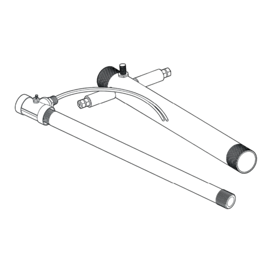
- Page 7 DIMENSIONS/MOUNTING NOTE: The inlet side of the heater is located where the leads/power feedthrus come out of the housing. Failure to install the heater in its proper orientation can result in heater damage and is not covered under the manufacturer’s warranty.
-
Page 8: Installation
INSTALLATION Caution: DO NOT Operate Heater Without Air WARNING: THE INLET AIR/GAS SIDE OF THE HEATER IS LOCATED CLOSEST TO WHERE THE POWER FEED-THRU CONNECTIONS ARE MADE. INSTALLING THE HEATER IN THE WRONG ORIENTATION WILL DAMAGE THE HEATER AND CAN CREATE ADDITIONAL HAZARDS AS A RESULT. MOUNT HEATER MOUNT HEATER WIRE HEATER BASED ON INSTRUCTIONS FOR MODEL... - Page 9 INSTALLATION For 3/8”, 1/2”, & 1-1/4” HEATER ONLY (#F038821, F038822, F038823, F038824, F038825 & F038826): 1. There are two (2) feed-thrus on the heater. Connect one power lead to one heater electrical feed-thru (ƒ one lead wire) and connect the other power lead to the other electrical feed-thru (or the other lead wire).
-
Page 10: Typical Wiring
TYPICAL WIRING 1Ø Heater with Closed Loop Control Temp Power Control Control TC – Output – TC + – Heater 3Ø Heater with Closed Loop Control 3Ø Disconnect – Temp Power Control Control TC – Output TC + – Heater... -
Page 11: Operation
OPERATION START-UP TURN ON AIR REFERENCE PERFORMANCE CURVES Set pressure or flow to desired operating level. Beginning on page 11 prior to operating heater. ENERGIZE MAIN POWER LINE SET DESIRED TEMPERATURE Via disconnect switch or circuit breaker on control cabinet. CONTROL AIRFLOW Ensure airflow is on before voltage is applied to heater. -
Page 12: Performance Curves
PERFORMANCE CURVES HOT AIR TOOLS MAXIMUM PERFORMANCE CURVE The attached performance curves show exit air temperatures at different airfl ows and voltages. Pressure readings (longer dashed lines) are measured at the inlet to the heater with no entrance or exit restrictions. Solid lines indicate safe, normal-life operating conditions. The shorter dash lines indicate marginal, shorter-life operating conditions leading to premature burnout. - Page 16 3. Verify inlet air temperature is below set point on INLET TEMPERATURE controller. iii.) If there is no continuity on any test, then contact your local TUTCO SureHeat representative for assistance. Remove entire heater assembly from system. Internal components are typically not replaceable.
-
Page 17: Limited Warranty
LIMITED WARRANTY TUTCO SureHeat warrants that all products to be delivered hereunder will be free from defects in material and workmanship at the time of delivery. TUTCO SureHeat’s obligation under this warranty shall be limited to (at its option) repairing, replacing, or granting a credit at the prices invoiced at the time of shipment for any of said products. - Page 18 Textiles Electric Industrial Air Heaters for Demanding High-Temperature Applications The technical data and specifi cations supplied in this operating manual are subject to change without prior notice. Contact TUTCO SureHeat for additional assistance. 603-418-7662 support@tutcosureheat.com orders@tutcosureheat.com 22 Industrial Drive Exeter, NH 03833 USA...
Need help?
Do you have a question about the F038821 and is the answer not in the manual?
Questions and answers