
Related Manuals for Tutco SureHeat Max Air F074723


Summary of Contents for Tutco SureHeat Max Air F074723
- Page 1 Max Air Heater FOR SAFETY AND LONG HEATER LIFE, CAREFULLY READ THIS MANUAL BEFORE USE.
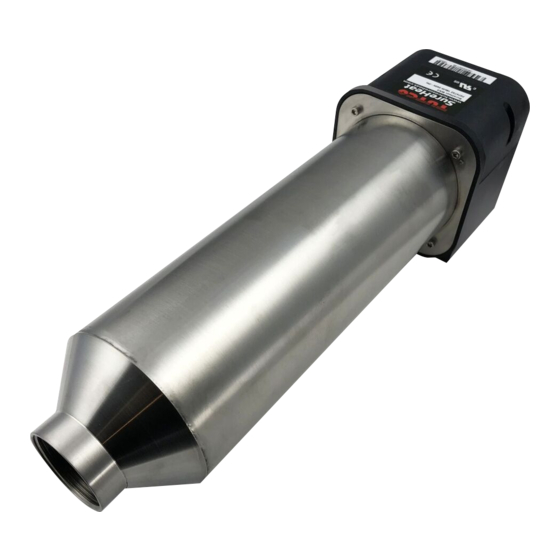
- Page 2 THANK YOU FOR CHOOSING THE MAX AIR HEATER TUTCO MAX AIR HEATER The Max provides a compact, efficient heater for heating air or inert gases up to 1400°F/760°C. The Max comes in various power ratings ranging from 6kW to 36kW. Two (2) type “K” thermo- couples with a convenient terminal block are included for ease of wiring.
- Page 3 WARNINGS! TUTCO SureHeat Process Air Heaters contain high watt-density elements and must be controlled carefully to prevent element failure. IMPORTANT: Be sure to read and understand this operating manual before turning the system ON. Follow all checklists shown in the manual. Failure to do so can cause a heat- er failure and may void warranty.
- Page 4 (TUTCO SureHeat Part #074835 – set to 300°F/150°C). (See Page 9 for proper wiring) • If using other forms of control you must always have sufficient airflow through the heater before applying power.
- Page 5 HEATER MODEL AND PARTS LIST Suggested Suggested Maximum Part Maximum Maximum Compatible wire size for wire size for Amperage controllers Number Wattage Voltage 60°C cable* 60°C cable* F074723 6.0kW 240 – 1Ø 50/60Hz 25.0 F075526, F078135 F074724 6.0kW 240 – 3Ø 50/60Hz 14.5 F078135 F074725...
- Page 6 DIMENSIONS/MOUNTING NOTE: The inlet side of the heater is located where the leads/power feedthrus come out of the housing. Failure to install NOTE: The inlet side of the heater is located where the leads/power feedthrus come out of the housing. Failure to install the heater in its proper orientation can result in heater damage and is not covered under the manufacturer’s warranty.
- Page 7 (0% output) before the contactor is engaged and immediately applying full power. 4 Use proper closed loop control (PID) settings. TUTCO SureHeat typically uses the following PID; Proportional (P), Integral (I) and Derivative (D); settings as a starting point for stable temperature control.
-
Page 8: Installation
K” THERMOCOUPLE WIRE must be Teflon Coated and Teflon Insulated, note RED is NEGATIVE ( - ). • S1 Type “K” Thermocouple Sensor on heater connects to INLET LIMIT controller. TUTCO SureHeat sets INLET TEMP LIMIT to 300°F/150°C. • S2 Type “K” Thermocouple Sensor on heater connects to EXIT TEMP controller. -
Page 9: Typical Wiring
SureHeat Max Heater ® Installation TYPICAL WIRING INLET LIMIT EXIT TEMP POWER TC– CONTROL TC– CONTROL CONTROL ALARM* RELAY** RELAY OUTPUT – + – – – HEATER SureHeat Max 1Ø ® – INLET LIMIT EXIT TEMP POWER TC– CONTROL TC– CONTROL CONTROL ALARM*... - Page 10 OPERATION (with Heater) START-UP REFERENCE PERFORMANCE CURVES CONNECT AIR SOURCE TO HEATER Beginning on page 11 prior to operating heater. TURN ON AIR ENERGIZE MAIN POWER LINE Set pressure or flow to desired operating level. Via disconnect switch or circuit breaker on control cabinet. CONTROL AIRFLOW During operation, with constant airflow, the exit temperature will vary only a few degrees from set point.
-
Page 11: Performance Curves
PERFORMANCE CURVES The attached performance curves show exit air temperatures at different airflows and voltages. Pressure readings (longer dashed lines) are measured at the inlet to the heater with no entrance or exit restrictions. MAX MAXIMUM PERFORMANCE CURVE Temperature measured by the internal S2 “K” thermocouple Minimum recommended airflow is 12 SCFM (340 SLPM) - Page 12 Solid lines indicate safe, normal-life operating conditions. The shorter dash lines indicate marginal, shorter-life operating conditions leading to premature burnout. With a known flow (or pressure) at the heater entrance, follow the flow (or pres- sure) line across until it meets the desired temperature curve. Drop a line straight down to intersect the x-axis. This point, along the “Heater volts –...
- Page 13 MAX PERFORMANCE CURVE – 18kW MAX PERFORMANCE CURVE – 36kW...
- Page 14 3. Verify inlet air temperature is below set point on INLET TEMPERATURE controller. iii.) If there is no continuity on any test, then contact your local TUTCO SureHeat representative for assistance. Remove entire heater assembly from system. Internal components are typically not replaceable.
-
Page 15: Limited Warranty
LIMITED WARRANTY TUTCO SureHeat warrants that all products to be delivered hereunder will be free from defects in material and workmanship at the time of delivery. TUTCO SureHeat’s obligation under this warranty shall be limited to (at its option) repairing, replacing, or granting a credit at the prices invoiced at the time of shipment for any of said products. - Page 16 Textiles Electric Industrial Air Heaters for Demanding High-Temperature Applications The technical data and specifi cations supplied in this operating manual are subject to change without prior notice. Contact TUTCO SureHeat for additional assistance. 800-258-8290 support@tutcosureheat.com orders@tutcosureheat.com 22 Industrial Drive Exeter, NH 03833 USA...
Need help?
Do you have a question about the Max Air F074723 and is the answer not in the manual?
Questions and answers