Advertisement
Quick Links
A-CS-CSX – UserManual
Installation and Operation Instructions
Part # A/CS, A/CS-L, A/CSX, A/CSX-L
Safety
This product is not intended to be used for Life or Safety applications.
!
This product is not intended for use in any hazardous or classified locations.
Disconnect and lock out all power sources before installation as severe injury or death may result from electrical
shock due to contact with high voltage wires.
Installation
Make sure that all installations are in compliance with all national and local electrical codes. Only qualified individuals that are
familiar with codes, standards, and proper safety procedures for high-voltage installations should attempt installation. The current
switches will not require external power, since the power for the current switch is induced from the conductor being monitored.
Warning: Never rely on the Red LED to determine whether power is present at the current switch. The Red LED will
indicate whether the current is above (LED On) or below (LED OFF) the fixed trip point.
The A/CS Series Current Switches should be used on Insulated Conductors Only! The current switch may be mounted in any
position using the (2) #8 x 3/4" Tek screws and the mounting holes in the base or snapped directly on to the 35mm DIN rail (See
Figures 1 & 2 below). Leave a minimum distance of 1" (3 cm) between the current switch and any other magnetic devices such as
contactors and transformers.
3X
Figure 1: Sensor Placed on Rail
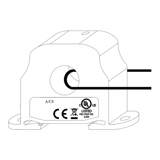
For applications in which the normal operating current is below the 0.5A trip point (See Figure 3 below), the conductor being
monitored may be looped through the sensor 4 times giving you a total operating current of 4X the original current.
Example: A small fan operating at 0.2A should be wrapped through the sensor 4 times to give you a total operating current of
0.8Amps flowing through the A/CS or another option is to use the A/CS-L.
INTEC Controls, 12700 Stowe Dr., Suite 100, Poway, CA 92064 | www.inteccontrols.com
Ph: (858) 578-7887 / (888) GO INTEC | Fx: (858) 578-4633 / (888) FX INTEC | Email: info@inteccontrols.com
12700 Stowe Drive, Suite 100, Poway, CA 92064 | Ph: (858) 578.7887 & (888) GO.INTEC | relevantsolutions.com/inteccontrols
Specifications subject to change without notice. | I0000135 Rev 6 | USA 150729 | Page 1 of 3
Please Read Instructions Carefully Before Installation!
A/CS
C
US
LISTED
IND.CO NT.EQ .
3JHX
Figure 3: Wires Through Sensors
3X
Figure 2: Sensor Removed From Rail
A/CS
C
US
LISTED
IND.CO NT.EQ .
3JHX
Advertisement

Subscribe to Our Youtube Channel
Related Manuals for Intec Controls A/CS


Summary of Contents for Intec Controls A/CS
- Page 1 (LED On) or below (LED OFF) the fixed trip point. The A/CS Series Current Switches should be used on Insulated Conductors Only! The current switch may be mounted in any position using the (2) #8 x 3/4” Tek screws and the mounting holes in the base or snapped directly on to the 35mm DIN rail (See Figures 1 &...
- Page 2 INTEC recommends the use of a two conductor 16 to 22 AWG shielded cable or twisted pair copper wire only for all current switch applications. A maximum wire length of less than 30 meters (98.4 feet) should be used between the A/CS Series current switches and the Building Management System or controller.
- Page 3 3JHX I0000135 Rev 6 INTEC Controls, 12700 Stowe Dr., Suite 100, Poway, CA 92064 | www.inteccontrols.com Ph: (858) 578-7887 / (888) GO INTEC | Fx: (858) 578-4633 / (888) FX INTEC | Email: info@inteccontrols.com 12700 Stowe Drive, Suite 100, Poway, CA 92064 | Ph: (858) 578.7887 & (888) GO.INTEC | relevantsolutions.com/inteccontrols...
Need help?
Do you have a question about the A/CS and is the answer not in the manual?
Questions and answers