Table of Contents
Advertisement
Quick Links
BUILDING SOLUTIONS
Analog Gas Controller
PolyGard
MGC2 - 04, 08, 12, 16, 20, 24
®
User Manual
June 2012
August 11, 2016 – Revision
PolyGard
®
is a registered trademark of MSR-Electronic GmbH
12700 Stowe Drive, Suite 100, Poway, CA 92064 | Ph: (858) 578.7887 & (888) GO.INTEC | relevantsolutions.com/inteccontrols
Advertisement
Table of Contents

Subscribe to Our Youtube Channel
Related Manuals for Intec Controls PolyGard MGC2-04


Summary of Contents for Intec Controls PolyGard MGC2-04
- Page 1 BUILDING SOLUTIONS Analog Gas Controller PolyGard MGC2 - 04, 08, 12, 16, 20, 24 ® User Manual June 2012 August 11, 2016 – Revision PolyGard ® is a registered trademark of MSR-Electronic GmbH 12700 Stowe Drive, Suite 100, Poway, CA 92064 | Ph: (858) 578.7887 & (888) GO.INTEC | relevantsolutions.com/inteccontrols...
-
Page 2: Table Of Contents
MGC2 – UserManual Specifications subject to change without notice. | USA 160811 | Page 2 of 34 1 Application ............................... 4 2 Description ............................... 4 2.1 Normal Mode ............................... 4 2.2 Alarm Mode ..............................4 2.3 Fault Mode ..............................4 3 Operating Instruction ............................ - Page 3 MGC2 – UserManual Specifications subject to change without notice. | USA 160811 | Page 3 of 34 4.8.3 SP Address Mode ..........................26 4.8.4 Language ............................26 4.8.5 Maintenance Concept ......................... 26 4.8.6 Average Function ..........................27 4.8.7 System Time, System Date ........................ 27 4.8.8 Service Password (Maintenance) .......................
-
Page 4: Application
MGC2 – UserManual Specifications subject to change without notice. | USA 160811 | Page 4 of 34 MGC2 Analog Gas Controller 1 Application The PolyGard MGC2 Gas Controller is used for monitoring and warning of toxic and combustible gases and vapors ®... -
Page 5: Operating Instruction
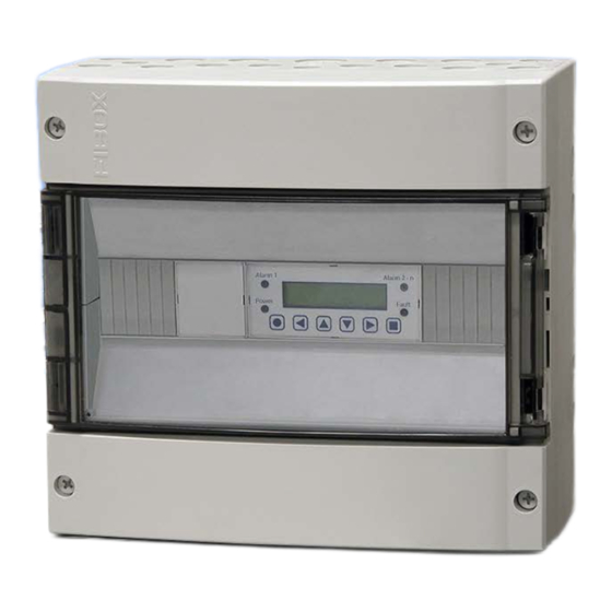
MGC2 – UserManual Specifications subject to change without notice. | USA 160811 | Page 5 of 34 3 Operating Instruction The complete configuration, parameterization and service is made via keypad user interface in combination with the display screen. Security is provided via two password levels. Alarm 1 Alarm 2 - n INTEC 13.06.13 11:45am Power Fault 3.1 Description Keypad User Interface Exits programming, returns to the previous menu level. -
Page 6: Code Levels
MGC2 – UserManual Specifications subject to change without notice. | USA 160811 | Page 6 of 34 3.3 Code Levels According to the regulations of all national and international standards for gas warning systems, all inputs and changes are protected by a four-digit numeric code (= password) against unauthorized intervention. All menu windows are visible without entering a code. -
Page 7: Menu Overview
MGC2 – UserManual Specifications subject to change without notice. | USA 160811 | Page 7 of 34 4 Menu Overview The Gas Controller MGC2 is operated via a simple and logical menu structure which is easy to learn. The operating menu contains the following levels: ... -
Page 8: Fault Management
MGC2 – UserManual Specifications subject to change without notice. | USA 160811 | Page 8 of 34 4.1 Fault Management The integrated fault management records the first 20 faults with date and time stamps in the menu “System Errors”. Additionally a record of the faults occurs in the “Error memory”, which can only be read and cancelled by the service technician. An actual fault activates the fault indication relay which is defined in the system parameter “Fault relay” after an internal fault delay time of 2 minutes. The yellow LED (Fault) starts to flash and the fault is displayed in plain text with date and time in the starting menu. In case of the fault of a connected transmitter the alarms defined in the menu “SP Parameter” are activated in addition. 4.1.1 Acknowledge a Fault Attention: Acknowledging of a fault is only possible after having removed the cause! In order to recognize situations where errors and faults occur sporadically and temporarily, their error states - even after return to normal operations - are displayed until they are manually acknowledged. -
Page 9: System Errors
MGC2 – UserManual Specifications subject to change without notice. | USA 160811 | Page 9 of 34 4.1.3 System Errors The following system error messages are recorded: SPXX > 22 mA Sensor signal at transmitter out of the measuring range. SPXX <... -
Page 10: Status Alarm
MGC2 – UserManual Specifications subject to change without notice. | USA 160811 | Page 10 of 34 4.2 Status Alarm Display of the actual alarms in plain text in the order of their arrival. Only those sensor points are displayed, where at least one alarm is active. -
Page 11: Menu Sensor Readings
MGC2 – UserManual Specifications subject to change without notice. | USA 160811 | Page 11 of 34 4.4 Menu Sensor Readings In this menu, the display shows the current value (CV), the gas type and the defined control mode (CV or AV mode) for each active sensor point. In the control mode Average Value (AV), both values (CV and AV) are displayed. The SP address and the display depend on the system parameter settings for the SP addressing mode (see 4.8.3) SP01 CO ppm... -
Page 12: Menu Relay Parameter
MGC2 – UserManual Specifications subject to change without notice. | USA 160811 | Page 12 of 34 4.5 Menu Relay Parameter Reading and changes of the parameter for each single alarm relay. Relay Parameter (Main menu) R 01 (Selection relay No. – only registered modules possible) Relay mode Relay Mode De-energized... -
Page 13: Latching Mode
MGC2 – UserManual Specifications subject to change without notice. | USA 160811 | Page 13 of 34 4.5.3 Latching Mode Definition of the latching function: The combination of the latching function and the automatic reset of the horn function cancels the effect of each other and therefore should be avoided. -
Page 14: External Operation Of Alarm Relay
MGC2 – UserManual Specifications subject to change without notice. | USA 160811 | Page 14 of 34 Acknowledge the horn relay Alarm 4 Gas concentration higher lower than threshold Time Relay 4 Acknowledging signal Reset command by external push-button or one of the operating keys. Special function Recurrence Alarm 4 Gas concentration higher... -
Page 15: Menu Sp Parameter
MGC2 – UserManual Specifications subject to change without notice. | USA 160811 | Page 15 of 34 4.6 Menu SP Parameter For reading and changing sensor point parameters for each bus and analog transmitter including registration of SP and assignment of the alarm relays. The presentation of the SP parameters depends on the system parameter settings for the GC mode (see 4.7.3). -
Page 16: Activate - Deactivate Sp
MGC2 – UserManual Specifications subject to change without notice. | USA 160811 | Page 16 of 34 Hysteresis Hysteresis 15 ppm See 4.6.6 Set delay time for alarm ON ON-Delay Time See 4.6.7 Set delay time for alarm OFF OFF-Delay Time See 4.6.7 Define control mode C/A Mode... -
Page 17: Selection Gas Type
MGC2 – UserManual Specifications subject to change without notice. | USA 160811 | Page 17 of 34 4.6.3 Selection Gas Type Assign gas type of the attached gas transmitter. Setting Measuring Symbol Description Function Unit Status type range SP01 Sensor point Carbon monoxide 0-300 Combustible gases... -
Page 18: Measuring Range Definition
MGC2 – UserManual Specifications subject to change without notice. | USA 160811 | Page 18 of 34 Direction of the alarm release In the gas measuring technique, most of the gases are monitored for their increasing concentration. For example oxygen, however, is monitored for its falling concentration. In this menu there is the definition how many of the 5 alarm thresholds monitor a falling concentration. 4.6.4 Measuring Range Definition The measuring range can be adjusted to the working range of the connected gas transmitter within 10 to 10000. 4.6.5 SP Signal Definition Gas transmitter using electro-chemical or catalytic beat gas sensors normally produce a linear signal, proportional to the gas concentration. -
Page 19: Control Mode Current Or Average Value
MGC2 – UserManual Specifications subject to change without notice. | USA 160811 | Page 19 of 34 4.6.8 Control Mode Current or Average Value Definition of the alarm evaluation by current value CV) or average value (AV). Symbol Description Default Status Function SP01 Sensor Point Selection SP No. / analog transmitter CV = Control by the current gas value Evaluation AV = Control by the average gas value Current / average value function see also 4.8.6... -
Page 20: Menu Data Logger
MGC2 – UserManual Specifications subject to change without notice. | USA 160811 | Page 20 of 34 4.7 Menu Data Logger This function is available from software version 9.02. But only if the GC-05 controller is equipped with a mini USB interface incl. USB special cable at the bottom side of the module. This option can’t be retrofit. Connect an USB device at the USB cable to use the data logger function. This USB device may be for example an USB flash drive. -
Page 21: Current Value
MGC2 – UserManual Specifications subject to change without notice. | USA 160811 | Page 21 of 34 4.7.2 Current Value Symbol Description Setting Status Function OFF = Current values of all registered SP are not recorded. Current value ON = Current values of all registered SP are recorded. Release of the current value recording of all active sensor points on the USB device in a CSV file. The file name is ... -
Page 22: Cv Log Rate
MGC2 – UserManual Specifications subject to change without notice. | USA 160811 | Page 22 of 34 4.7.3 CV Log Rate Setting of the time interval in which the current values of all registered SP are stored (in seconds). Symbol Description Setting Status Function... -
Page 23: Error Status
MGC2 – UserManual Specifications subject to change without notice. | USA 160811 | Page 23 of 34 4.7.5 Error Status Symbol Description Setting Status Function = Faults are not stored Error status = Faults are stored Release of the fault recording for all active sensor points on the USB device in the common CSV file for alarms and faults. Internal structure of the file (The headlines are not written in the file!) Current time Source Error date + time... -
Page 24: Menu System Parameter
MGC2 – UserManual Specifications subject to change without notice. | USA 160811 | Page 24 of 34 4.8 Menu System Parameter Display and changes of the system parameter for the Gas Controller System Parameter (Main menu) Service Mode See 4.8.1 Software Version See 4.8.2 MGC2 XX... - Page 25 MGC2 – UserManual Specifications subject to change without notice. | USA 160811 | Page 25 of 34 GC Address See 4.8.9 Fault Relay See 4.8.10 Latching Reset See 4.8.11 Power ON time See 4.8.12 30 s EP Module 0 See 4.8.13 Relay+SP active EP Module 1 See 4.8.13...
-
Page 26: Service Mode
MGC2 – UserManual Specifications subject to change without notice. | USA 160811 | Page 26 of 34 4.8.1 Service Mode For calibration and service work, the alarms are not transmitted to the alarm relays when the service mode is active (ON). The service mode ON is reset automatically after 60 minutes or manually in the menu “Service Mode”. -
Page 27: Average Function
MGC2 – UserManual Specifications subject to change without notice. | USA 160811 | Page 27 of 34 4.8.6 Average Function Not used in USA. The each active sensor point the Gas Controller calculates the arithmetic average value out of 10 measurements got within the time unit defined in the menu „AV-time“. Depending on the definition of the operating ... -
Page 28: Define The Failure Relay
MGC2 – UserManual Specifications subject to change without notice. | USA 160811 | Page 28 of 34 4.8.10 Define the Failure Relay In this menu you can define one of the relays as fault indication relay. See also fault management (4.1) Symbol Description Default Status Function Fault Relay 0-30 = Definition of the fault indication relay 4.8.11 Acknowledge a Relay in Latching Mode by a DI This configurable functionality is available from version 9.02. -
Page 29: Error Indicator System Bus
MGC2 – UserManual Specifications subject to change without notice. | USA 160811 | Page 29 of 34 The table shows the assignment of the relay numbers and of the analog in/outputs to the EP module addresses. Module Analog Relay Analog Symbol Description Default... -
Page 30: Relay Multiplication
MGC2 – UserManual Specifications subject to change without notice. | USA 160811 | Page 30 of 34 4.8.16 Relay Multiplication This function is available from version 9.02. With the relay multiplication table, it is possible in the MGC2 system, to assign an alarm to multiple relays. There is a maximum of 20 entries for In-relays and Out-relays. -
Page 31: Programming Operation
MGC2 – UserManual Specifications subject to change without notice. | USA 160811 | Page 31 of 34 5 Programming Operation Before beginning startup the wiring of the Controller including all field devices must be completely terminated! After switching the power supply “ON” and the end of the Power-On Time, then the Controller is ready for use. The electrochemical sensor needs a warm up time of 1 hour to reach its highest accuracy. The Controller is delivered with standard parameters and stages/set points. The assignment of the relays to the individual stages can occur at startup unless arrangements have been made with the factory for programming. -
Page 32: Relay Setup
MGC2 – UserManual Specifications subject to change without notice. | USA 160811 | Page 32 of 34 5.1.3 Relay Setup Available Relay Outputs, max.: MGC2-04 = 5 | MGC2-08 = 10 | MGC2-12 = 15 | MGC2-16 = 20 | MGC2-20 = 20 | MGC2-24 = 20 Relay Mode Steady... -
Page 33: Sensor Setup
MGC2 – UserManual Specifications subject to change without notice. | USA 160811 | Page 33 of 34 5.1.4 Sensor Setup Available Analog Inputs, max.: MGC2-04 = 4 | MGC2-08 = 8 | MGC2-12 = 12 | MGC2-16 = 16 | MGC2-20 = 20 | MGC2-24 = 24 PolyGard is a registered trademark of MSR-Electronic GmbH ®... -
Page 34: Notes & General Information
® of shipment against defects in material or workmanship. Should any evidence of defects in material or workmanship occur during the warranty period, INTEC Controls will repair or replace the product at their own discretion, without charge. This warranty does not apply to units that have been altered, had attempted repair, or been subject to abuse, accidental or otherwise.
Need help?
Do you have a question about the PolyGard MGC2-04 and is the answer not in the manual?
Questions and answers