
Related Manuals for elco FEPN-04UA-M12-T

Summary of Contents for elco FEPN-04UA-M12-T
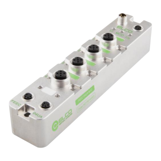
- Page 1 Slim67 Analog I/O Module ----Profinet System Manual ELCO (Tianjin) Electronics Co., Ltd 04/2023 Version 1.2...
-
Page 2: Preface
This manual presumes a general knowledge in the field of automation engineering and describes the components based on the data valid at the time of its release. ELCO reserves the right of including a product information for each new component, and for each component of a later version. -
Page 3: Table Of Contents
Table of contents Preface ........................... 2 1. Product overview ...................... 4 1.1 Introduction ........................4 1.2 Applications ........................4 1.3 Features ..........................4 2. Technical characteristics .................... 5 2.1 Hardware parameters ....................5 2.2 LED Indication ........................7 2.3 General system layout ....................7 3. -
Page 4: Product Overview
LED status display, channel level protection and diagnosis 1.4 Product type list Type Description 4-Point configurable analog channel Current or voltage input/output signals and FEPN-04UA-M12-T thermocouple and resistance signals can be connected as required Short Circuit Protection and Diagnosis Slim67 Profinet Analog I/O Module 4 / 34... -
Page 5: Technical Characteristics
2. Technical characteristics 2.1 Hardware parameters Ordering data Product type FEPN-04UA-M12-T Description Slim IP67 analog module Communication Protocol Profinet Operating mode Auto-negotiation, Auto-MDI/MDI-X Transfer rate 10/100 Mbps Addressing System automatic allocation Power supply 工作电压 24 VDC(18…30 VDC) Current consumption Max. 200mA System&Signal supply... - Page 6 Current & Voltage:12 ms Switching time Thermocouple:50 ms Measurement accuracy ± 0.3% Output channels Max. 4 Current:0…20mA,4…20mA Output type Voltage:0…10V Current:<450Ω Internal impedance Voltage:>1kΩ Resolution 16 Bit Switching time 12 ms Measurement accuracy ± 0.3% Diagnostics Communication indication LED indication,Communication message Voltage detection Support,Low voltage alarm Short-circuit &...
-
Page 7: Led Indication
2.2 LED Indication The operating status of the module can be clearly displayed by the LED indicator. Comm.status COM Module status MOD System power PWR Channel status X Profinet_IN Lk1 Profinet_OUT Lk2 Slim67 Profinet Analog I/O Module 7 / 34... -
Page 8: General System Layout
2.3 General system layout The following figure shows an example of a conventional Profinet system module connection, which is powered by 24VDC power supply to three modules. Profinet network connects modules through switches or cascades. The further modules can also use more switches to expand the connection distance. Slim67 Profinet Analog I/O Module 8 / 34... -
Page 9: Installing
3. Installing 3.1 Mounting dimensions Slim67 Profinet Analog I/O Module 9 / 34... -
Page 10: Mounting Position, Mounting Dimensions
3.2 Mounting position, mounting dimensions Slim67 analog module can be mounted in any position because of IP67's high protection level and excellent anti-vibration and anti-interference capability. Slim67 analog module adopts a uniform shape size. The following table shows the dimensions of the module: Dimensions Mounting width 32 mm... -
Page 11: Wiring Slim67 Analog Module
3.3 Assigning names in PROFINET I/O devices Each Profinet protocol Slim67 analog module is assigned to a unique device ID (i.e. MAC address) at the factory, while addressing to each Slim67 analog module based on device name during configuration and as per the user program. Therefore, it’s necessary to assign names for each Slim67 analog module before the configuring and debugging. - Page 12 5) Assign the new IP address directly to Slim67 analog module by clicking the button "Assign IP Configuration". (IP address assignment can also be carried out during configuration of the I/O Devices) 6) Now, with the new assigned device name as an identifier of the Slim67 analog module, you can configure and debug in the program.
- Page 13 3.4 Wiring Slim67 analog module Please connect according to the basic electrical specifications. For personal and equipment safety, we recommend disconnecting the power supply during wiring operation. 3.4.1 Connecting Slim67 analog module to protective earth (PE) Always connect the Slim67 analog module to protective earth. ...
- Page 14 2)Power out connector view (Female) 3)Power definition Terminal Function Power supply Module and input signal 1L+ Output signal 2L+ Module and input signal 1M Output signal 2M Slim67 Profinet Analog I/O Module 14 / 34...
- Page 15 3.4.3 Slim67 analog module BUS connection Slim67 analog module, supporting Profinet protocol, transmits signals by a shielded cable, M8-4pin connector. 1)BUS-In connector view (Female) 2)BUS-Out connector view (Female) 3)Bus definition Terminal Function Cable color Transmit Data( TD+ ) Yellow Receive Data( RD+ ) White Orange Receive Data( RD- )
- Page 16 3.4.4 Slim67 analog module signal connection I/O signals of Slim67 analog module are connected by standard M12 A-Code 5-pin connectors, and each port can connect up to one signal (input or output). 1)Signal connector view (Female) 2)Digital signal interface definition Terminal M12 connector Power supply 24V+...
- Page 17 M12-T supports this connection. b) Four-wire input --- 1 connector connects 1 four-wire input, FEPN-04UA- M12-T supports this connection. c) Voltage input- 1 connector connects 1 voltage input, FEPN-04UA-M12-T supports this connection. Slim67 Profinet Analog I/O Module 17 / 34...
- Page 18 Current output- 1 connector connects 1 current output, FEPN-04UA-M12-T supports this connection. e) Voltage output- 1 connector connects 1 voltage output, FEPN-04UA-M12-T supports this connection. f) Two-wire thermal resistance signal — 1 connector connects 1 two-wire thermal resistance signal, FEPN-04UA-M12-T supports this connection.
- Page 19 g) Thermocouple signal —1 connector connects 1 thermocouple signal, FEPN- 04UA-M12-T supports this connection. Slim67 Profinet Analog I/O Module 19 / 34...
-
Page 20: Configuration Commissioning
Configuration of the Slim67 analog module via GSD file (XML format) and the standard Profinet IO GSD file for the Slim67 will be integrated into the user’s system. You can visit the ELCO website to get the latest GSD file or call the hotline to contact technical support. - Page 21 3)The new added Slim67 analog module is shown in the directory of hardware "Other field devices>PROFINETIO > I/O > ELCO > Slim IP67 Analog module". 4)The user can configure the Slim67 analog module with Portal according to the actual situation.
-
Page 22: Signal Address Assignment
(Pin1~Pin5) for connection. The following model list shows the corresponding relationship between the signal status of each connector and the bytes transmitted by the Profinet bus. FEPN-04UA-M12-T takes 12 bytes Input and 8 bytes Output. Byte Byte... -
Page 23: Instruction Of Analog Value
4.3 Instruction of Analog Value PLC controller processes analog values in a binary system; the analog input module transfers analog process signals into digital signals; the analog output module transfers the digital output value into an analog signal. Digital analog values are suitable to the same rated input and output value; each analog signal occupies 1 word PLC address, i. - Page 24 Analog value within unipolar current input/output range: System Value Input/Output Range Decimalism hexadecimal 0~20mA 4~20mA 104.999% 32767 7FFF ≥ 23.7 mA ≥ 22.96 mA Overflow, lock the maximum 31208 79E8 Overshoot range 100% 31207 79E7 20 mA 20 mA 23405 5B6D 15 mA...
- Page 25 Analog value within PT x00 thermal resistance: System Value Input/Output Range Decimalism hexadecimal -200~+850 ℃ ≥ 850.1 ℃ 32767 7FFF Overflow, lock the maximum 850 ℃ 8500 2134 637.5 ℃ 6375 18E7 1 ℃ 0 ℃ Rated range -1 ℃ FFF6 -150 ℃...
- Page 26 This section, through a case of connection configuration in actual operation process, makes the users fully understand how to use the Slim67 analog distributed I/O system. In this case, using the ELCO Slim67 analog module as Profinet slave station to connect the Siemens PROFINET controller CPU1211C under the condition that all power and bus connection have been completed.
- Page 27 2)Install GSD files for Slim67 analog module products. a)Select "Options"->"Manage General Station Description File (GSD)" in the menu bar. b)Select the version of the GSD file to be imported and click ‘Install’. Slim67 Profinet Analog I/O Module 27 / 34...
- Page 28 3)Double-click "Add New Device" on the left and select the PLC model in the "Controller" window. 4)Double-click the "Device Configuration" window on the left, and in the "Network View" window, select "Properties"->"PROFINET Interface [X1]" -> "Ethernet Address" and set the IP address of the PLC. Slim67 Profinet Analog I/O Module 28 / 34...
- Page 29 "Devices & Networks" on the left to enter the "Network View" interface and select FEPN-04UA-M12-T through "Other Field Devices-> PROFINET IO-> I / O-> ELCO-> Compact Slim Analog->Slim IP67 Analog module" in "Hardware Catalog", double-click or drag to add to the network.
- Page 30 c)Slim67 analog module and PLC complete communication connection. 6)Modify Slim67 analog module device name and IP address settings a)Click the Slim67 analog module in the "Network View", select "Properties-> PROFINET Interface-> Ethernet Addresses", set the I Slim67 analog module device name elco67 in the window, and set the IP address. (It should be on the same network segment as the IP address of the PLC) Slim67 Profinet Analog I/O Module 30 / 34...
- Page 31 b)Click "Online Access" in the "Project Tree" on the left, find the name of the upper computer network card, double-click "Update accessible devices", and then the name and MAC address of the connected Slim67 analog module will be scanned. Double-click " Online and Diagnostics ", modify the device name to elco67 in this interface.
- Page 32 7)Enter the "Device View" interface and select "Attributes-> General-> Module Parameters" of "Slim Fixed 4 channel Analog Module". At this time, the user can modify the module parameters. 8)After saving and compiling, download the configuration to the PLC. Slim67 Profinet Analog I/O Module 32 / 34...
-
Page 33: Alarm Diagnosis
With the LED indicator on the Slim67 analog module, users can easily and quickly determine the current working status of the module. (For the appearance of the indicator, please refer to Section 2.2 "LED Indication") FEPN-04UA-M12-T indicator Name Status Meaning Fault cause –... -
Page 34: Process Image Area Of Slim67 Analog Module
5.2 Process image area of Slim67 analog module Each Slim67 analog module occupies the address area in the PLC process image area, which is used to transmit the gateway's communication and power supply abnormal status, as follows: IN=4 bytes,OUT=0 byte Byte Bit_7 Bit_6...
Need help?
Do you have a question about the FEPN-04UA-M12-T and is the answer not in the manual?
Questions and answers