Table of Contents
Advertisement
Available languages
Available languages
Quick Links
Installation Instructions
Cellular Gateway
Read this Manual BEFORE using this equipment.
Failure to read and follow all safety and use information
can result in death, serious personal injury, property
damage, or damage to the equipment.
Keep this Manual for future reference.
Installing the Cellular Gateway
Ensure all power supply to the Cellular Gateway is turned off before making any connections to the
Cellular Gateway. Failure to do so may result in electrocution, personal injury, and/or death.
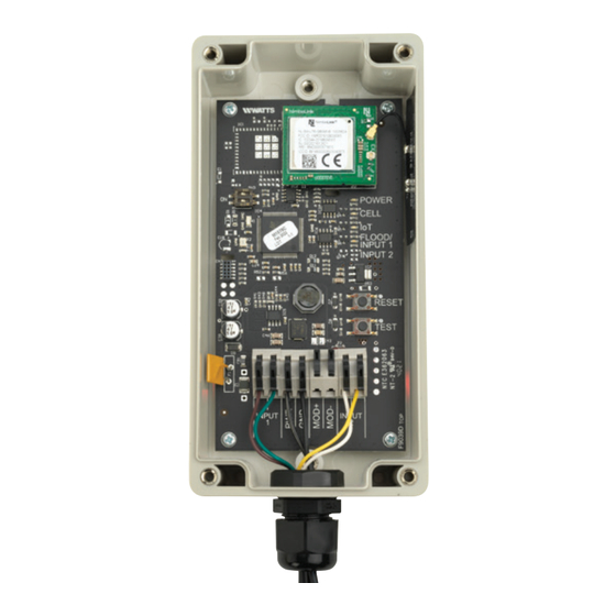
When identifying a location to mount the Cellular Gateway, the device must be placed away
from large metal objects and structures that can block cellular signal. Additionally, the cellular
antenna is located on the upper right inner side wall of the enclosure). When mounting,
ensure that this of the device is away from any walls, wires, pipes, or other obstructions,
especially anything metallic.
1. Before mounting, apply power to the Cellular Gateway to ensure there is adequate
cell coverage. On startup, the CELL LED will blink at a rate of 1sec. This indicates it is
searching for a cell connection. Once connected it turns steady blue. If connection is
poor, it will blink with short OFF pulse every second. If there is a poor or no connection,
find a new location.
2. Mount the Cellular Gateway at the selected location, using the mounting tabs and
screws provided with the kit. Screws to attach the unit to the wall are not included.
3. Using the four-conductor cable supplied with the kit, connect the Sensor Control Monitor
to the Cellular Gateway. Route wires from TB9 through the Cellular Gateway's wiring
gland and connect.
RLY0 to INPUT1
RLY1 to IMPUT2
Six feet of cable is supplied with the unit, but the Cellular Gateway can be located up to
100 feet away from the Sensor Control Monitor. If additional wire is used. it must meet
the required rating (300V, 18-24 AWG).
4. To prevent water or dust from entering the cellular gateway, control box & relay box,
tighten all wiring glands.
5. Apply power (24VDC) to the Cellular Gateway. If wiring power from Sensor Control
Monitor to Cellular Gateway, route a two-conductor cable through the wiring glands and
connect
+24IN to PWR
PGND to GND
IS-CellularGateway
Cellular Gateway
Advertisement
Table of Contents

Subscribe to Our Youtube Channel
Related Manuals for Watts Mueller Cellular Gateway


Summary of Contents for Watts Mueller Cellular Gateway
- Page 1 IS-CellularGateway Installation Instructions Cellular Gateway Cellular Gateway Read this Manual BEFORE using this equipment. Failure to read and follow all safety and use information can result in death, serious personal injury, property damage, or damage to the equipment. Keep this Manual for future reference. Installing the Cellular Gateway Ensure all power supply to the Cellular Gateway is turned off before making any connections to the Cellular Gateway.
- Page 2 Cellular Gateway Cellular Connection to Internet Wired to Sensor Control Monitor Setting Up the Cellular Gateway Start-Up – Upon start-up, the POWER LED will light up a steady green to indicate power is supplied. The Cellular Gateway will automatically go into its start-up sequence. During the start-up sequence, the CELL and IoT LED will blink blue, indicating the Cellular Gateway is searching for a cellular connection.
- Page 3 Registering SentryPlus Alert 1. Using a smart phone or tablet, scan the QR code on the side on the Cellular Gateway, or go to https://connected. syncta.com 2. When prompted, enter the Device ID. The Device ID is the set of numbers printed beside the QR code on the side of the Cellular Gateway.
-
Page 4: Startup Sequence
COLOR STATE DEFINITION Steady Green Green LED turns on - when power is applied Cell LED blinks Trying to establish a cellular connection. IoT LED blinks Trying to establish a connection to the Watts Cloud. - Page 5 The IoT LED indicates whether or not there is a connection to the Cloud. COLOR STATE DEFINITION SOLUTION Steady Blue There is a connection to the Watts Cloud. Blinking There is not a connection to See No Connection to the Cloud on the Watts Cloud. Trying to establish page 12. connection.
-
Page 6: Troubleshooting Guide
This section provides troubleshooting solutions to the most common issues if your Cellular Gateway is not working correctly. If you are unable to resolve your issue, contact your local Watts representative to order a replacement device. Poor or No Cellular Reception Poor or no cellular reception will cause notifications to not work. -
Page 7: Power Led Is Off
If the POWER LED is off, check that 24VDC is correctly applied to the PWR and GND terminals. No Connection to the Cloud If the IoT LED is blinking, there is no connection to the Watts Cloud. If the device is not working, review the possible cause and solution below. Possible Cause There is a disruption in service between the Watts Cloud and the Cellular Gateway. - Page 8 State to State. You should consult applicable state laws to determine your rights. USA: T: (800) 334-6259 • MuellerSteam.com Latin America: T: (52) 55-4122-0138 • MuellerSteam.com IS-CellularGateway 2331 1917133 © 2023 Watts...
- Page 9 IS-CellularGateway Instructions d’installation Passerelle cellulaire Passerelle cellulaire Lisez ce manuel AVANT d’utiliser cet équipement. Le fait de ne pas lire et respecter toutes les informations de sécurité et d’utilisation peut entraîner la mort, des blessures graves, des dommages à la propriété ou à l’équipement.
- Page 10 Passerelle cellulaire Raccordement cellulaire à Internet Connexion à l’appareil régulateur à sonde Configuration de la passerelle cellulaire 1. Démarrage – Au démarrage, le voyant DEL POWER se fige en vert pour indiquer que l’alimentation est assurée. La passerelle cellulaire entame automatiquement sa séquence de démarrage.
- Page 11 Enregistrement de SentryPlus Alert 1. Avec un téléphone intelligent ou une tablette, scannez le code QR sur le côté sur la passerelle cellulaire, ou allez sur https://connected.syncta.com. 2. Lorsque vous y êtes invité, saisissez l’identifiant du dispositif. L’identifiant du dispositif est l’ensemble des nombres imprimés à...
-
Page 12: Vue D'ensemble
Le fait de ne pas lire et respecter toutes les informations de sécurité et d’utilisation peut entraîner la mort, des blessures graves, des dommages à la propriété ou à l’équipement. Pour toute question, visitez Watts.com. Conservez ce Manuel aux fins de référence. - Page 13 COULEUR ÉTAT/PROVINCE DÉFINITION SOLUTION Bleu figé Il y a une connexion avec le nuage S.O. de Watts. Il n’y a pas de connexion avec Clignotement Voir « Aucune connexion au nuage » le nuage de Watts. Tentative à la page 12. d’établissement de connexion.
-
Page 14: Guide De Dépannage
Cette section fournit des solutions de dépannage aux problèmes les plus courants si votre passerelle cellulaire ne fonctionne pas correctement. Si vous ne parvenez pas à résoudre votre problème, communiquez avec votre représentant Watts local pour commander un dispositif de remplacement. Réception cellulaire faible ou inexistante Une réception cellulaire faible ou inexistante peut empêcher les notifications de fonctionner. - Page 15 PWR et GND. Aucune connexion au nuage Si le voyant DEL IoT clignote, il n’y a pas de connexion au nuage de Watts. Si le dispositif ne fonctionne pas, passez en revue la cause possible et la solution ci-dessous. Cause possible Il y a une interruption de service entre le nuage de Watts et la passerelle cellulaire.
- Page 16 également avoir d’autres droits, lesquels varient d’un État à l’autre. Vous devez donc prendre connaissance des lois d’État applicables pour votre cas particulier. É.-U. : Tél. : (800) 334-6259 • MuellerSteam.com Amérique latine : Tél. : (52) 55-4122-0138 • MuellerSteam.com IS-CellularGateway 2331 1917133 © 2023 Watts...
- Page 17 IS-CellularGateway Instrucciones de instalación Puerta de Puerta de enlace celular enlace celular Lea este manual ANTES de utilizar este equipo. El hecho de no leer y seguir toda la información de seguridad y de uso, puede provocar la muerte, lesiones personales serias, daños materiales o daños en el equipo.
- Page 18 Puerta de enlace celular Conexión celular a Internet Cableado al monitor de control del sensor Configuración de la puerta de enlace celular 1. Arranque: al arrancar, el LED DE ALIMENTACIÓN se iluminará de color verde fijo para indicar que se suministra energía. La puerta de enlace celular pasará automáticamente a su secuencia de inicio.
- Page 19 Registro de la alerta de SentryPlus 1. Usando un teléfono inteligente o tableta, escanee el código QR que se encuentra al costado de la puerta de enlace celular o visite https://connected.syncta.com 2. Cuando se le solicite, ingrese la ID del dispositivo. El ID del dispositivo es el conjunto de números impresos junto al código QR en el lateral de la puerta de enlace celular.
-
Page 20: Descripción General
A continuación se muestra la secuencia de inicio que pasará el dispositivo si todo funciona correctamente. COLOR ESTADO DEFINICIÓN Verde fijo El LED verde se enciende cuando se aplica energía El LED de la Intentando establecer una conexión celular. celda parpadea El LED de IoT Intentando establecer una conexión con Watts Cloud. parpadea... -
Page 21: Fuente De Energía
El LED de IoT indica si hay o no una conexión a la nube. COLOR ESTADO DEFINICIÓN SOLUCIÓN Azul fijo Hay una conexión con Watts Cloud. Parpadeante No hay una conexión con Watts Consulte Sin conexión a la nube en la Cloud. Intentando establecer página 12. -
Page 22: Guía De Resolución De Problemas
Esta sección proporciona soluciones de solución de problemas para los problemas más comunes si su puerta de enlace celular no funciona correctamente. Si no puede resolver su problema, comuníquese con su representante local de Watts para solicitar un dispositivo de reemplazo. Recepción celular deficiente o nula Una recepción celular deficiente o nula hará... - Page 23 Si el LED DE ALIMENTACIÓN está apagado, verifique que los 24VDC se apliquen correctamente a los terminales PWR y GND. Sin conexión a la nube Si el LED de IoT parpadea, no hay conexión a Watts Cloud. Si el dispositivo no funciona, revise la causa y la solución posibles a continuación. Causa posible Hay una interrupción en el servicio entre Watts Cloud y la puerta de enlace celular.
- Page 24 Esta garantía limitada le otorga derechos legales específicos y es posible que tenga otros derechos que varían de un estado a otro. Debe consultar las leyes estatales correspondientes para determinar sus derechos. EE. UU.: Tel.: (800) 334-6259 • MuellerSteam.com Latinoamérica: Tel.: (52) 55-4122-0138 • MuellerSteam.com IS-CellularGateway 2331 1917133 © 2023 Watts...
Need help?
Do you have a question about the Mueller Cellular Gateway and is the answer not in the manual?
Questions and answers