Table of Contents
Advertisement
Quick Links
AERCO ProtoNode FPC-N34 & FPC-N35 User Manual
AERCO ProtoNode FPC-N34 and FPC-N35 User Manual
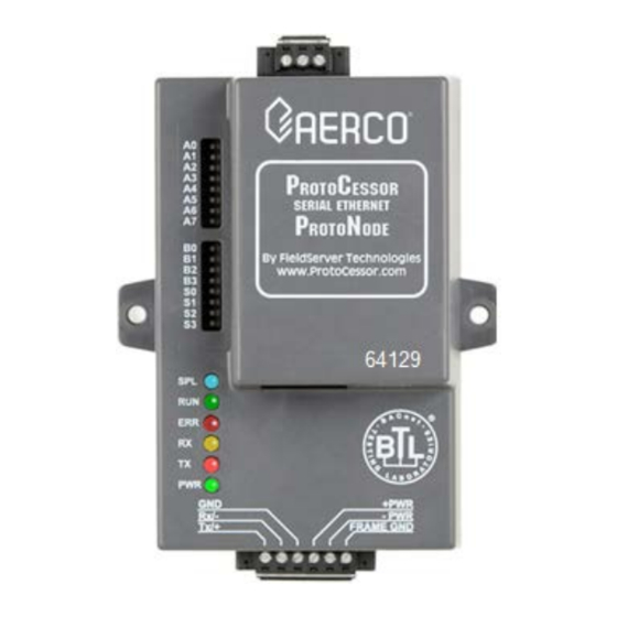
AERCO Serial
ProtoNode FPC-N34
Part Number 64129
For interfacing with the following AERCO products:
• AM Series
• C-More
For interfacing with the following Building Automation Systems:
• BACnet MS/TP
• BACnet/IP
This user manual applies
FPC-N34 (P/N 64129) and FPC-N35 (P/N 64130)
For ProtoNode RER (P/N 64084) and LER (P/N 64085) see
user manual OMM-0080, GF-129
Latest Revision: March 07, 2017
OMM-0107_0B
GF-150
User Manual
• Modulex
• ECS/SmartPlate
• Modbus TCP/IP
• Modbus RTU
only
AERCO International, Inc. • 100 Oritani Dr. • Blauvelt, NY 10913
Ph.: 800-526-0288
AERCO LonWorks
ProtoNode FPC-N35
Part Number 64130
• BMS/BMSII/ACS
• Metasys N2
• LonWorks
to ProtoNode Models
OMM-0107
GF-150
Page 1 of 108
03/07/2017
Advertisement
Table of Contents

Related Manuals for Watts Aerco ProtoNode FPC-N34


Summary of Contents for Watts Aerco ProtoNode FPC-N34
- Page 1 OMM-0107 AERCO ProtoNode FPC-N34 & FPC-N35 User Manual GF-150 User Manual AERCO ProtoNode FPC-N34 and FPC-N35 User Manual AERCO Serial AERCO LonWorks ProtoNode FPC-N34 ProtoNode FPC-N35 Part Number 64129 Part Number 64130 For interfacing with the following AERCO products: • AM Series •...
- Page 2 OMM-0107 AERCO ProtoNode FPC-N34 & FPC-N35 User Manual GF-150 User Manual Technical Support (Mon-Fri, 8am-5pm EST) 1-800-526-0288 Website: www.aerco.com Certifications BTL MARK – BACNET TESTING LABORATORY The BTL Mark on ProtoNode FPC-N34 is a symbol that indicates that a...
-
Page 3: Table Of Contents
OMM-0107 AERCO ProtoNode FPC-N34 & FPC-N35 User Manual GF-150 User Manual TABLE OF CONTENTS Quick Start Guide ................................. 6 CHAPTER 1. Introduction ..........................7 1.1 ProtoNode Gateway .........................7 CHAPTER 2. BACnet/LonWorks Setup for ProtoNode FPC-N34/FPC-N35 ......11 2.1 Record Identification Data ...................... 11 2.2 Point Count Capacity and Registers per Device .............. - Page 4 OMM-0107 AERCO ProtoNode FPC-N34 & FPC-N35 User Manual GF-150 User Manual CHAPTER 8. CAS BACnet Explorer for Validating ProtoNode in the Field ......37 8.1 Downloading the CAS Explorer and Requesting an Activation Key ........37 8.2 CAS BACnet Setup ........................ 38 8.2.1 CAS BACnet MS/TP Setup ........................
- Page 5 OMM-0107 AERCO ProtoNode FPC-N34 & FPC-N35 User Manual GF-150 User Manual Appendix I-4: AM Status Parameters Table ................100 Appendix I-5: Cascade Connection of AM Boiler with ProtoNode ..........101 Appendix J: Reference ..........................104 Appendix J-1: Specifications ..................... 104 Appendix J-2: Compliance with UL Regulations ................
-
Page 6: Quick Start Guide
OMM-0107 AERCO ProtoNode FPC-N34 & FPC-N35 User Manual GF-150 User Manual Quick Start Guide • Auto-Discovery connection points are limited by available memory in the device. • Auto-Discovery is not available in SSD mode required for BST (Boiler Sequencing Technology) and WHM (Water Heater Management). -
Page 7: Chapter 1. Introduction
AERCO ProtoNode FPC-N34 & FPC-N35 User Manual CHAPTER 1 – Introduction CHAPTER 1. Introduction 1.1 ProtoNode Gateway ProtoNode is an external, high performance Building Automation multi-protocol gateway that is preconfigured to Auto-Discover any AERCO products (hereafter called a “device”) connected to the ProtoNode and automatically configure them for BACnet®... - Page 8 AERCO ProtoNode FPC-N34 & FPC-N35 User Manual CHAPTER 1 – Introduction AERCO’s multi-protocol communications gateway supports integration of AERCO devices with customers’ building control and energy management systems. The plug-n-play package supports integration with BACnet/IP, BACnet MS/TP, LonWorks, and Johnson Controls Metasys N2 systems.
- Page 9 AERCO ProtoNode FPC-N34 & FPC-N35 User Manual CHAPTER 1 – Introduction AERCO’s Communications Gateway (ProtoNode) is an external, high performance, Building Automation multi-protocol gateway that has been preprogrammed for AERCO’s equipment to support BACnet® MS/TP, BACnet/IP, Metasys® N2 by JCI, Modbus TCP, and LonWorks®...
- Page 10 AERCO ProtoNode FPC-N34 & FPC-N35 User Manual CHAPTER 1 – Introduction (This Page Left Intentionally Blank) AERCO International, Inc. • 100 Oritani Dr. • Blauvelt, NY 10913 Page 10 of 108 OMM-0107_0B Ph.: 800-526-0288 03/07/2017 GF-150...
-
Page 11: Chapter 2. Bacnet/Lonworks Setup For Protonode Fpc-N34/Fpc-N35
AERCO ProtoNode FPC-N34 & FPC-N35 User Manual CHAPTER 2 – BACnet/LonWorks Setup CHAPTER 2. BACnet/LonWorks Setup for ProtoNode FPC-N34/FPC-N35 2.1 Record Identification Data Each ProtoNode has a unique part number located on the side or the back of the unit. This number should be recorded, as it may be required for technical support. -
Page 12: Configuring Device Communications
AERCO ProtoNode FPC-N34 & FPC-N35 User Manual CHAPTER 2 – BACnet/LonWorks Setup 2.3 Configuring Device Communications 2.3.1 Set Modbus COM setting on all of the Devices connected to the ProtoNode • All of the Serial devices connected to ProtoNode MUST have the same Baud Rate, Data Bits, Stop Bits, and Parity settings. -
Page 13: Enabling Auto-Discovery (Not Used On Bst Or Whm)
AERCO ProtoNode FPC-N34 & FPC-N35 User Manual CHAPTER 2 – BACnet/LonWorks Setup S0 S1 S2 S3 S0 S1 S2 S3 S0 – S3 DIP Switches S Bank DIP Switch Location ProtoNode FPC-N34 S Bank DIP Switches Profile BACnet/IP BACnet MS/TP... -
Page 14: Manually Selecting Your Equipment
AERCO ProtoNode FPC-N34 & FPC-N35 User Manual CHAPTER 2 – BACnet/LonWorks Setup 2.4.3 Manually Selecting Your Equipment A laptop or PC is required to do this. This cannot be done for BST or WHM The ProtoNode’s device port can be pre-configured for your equipment. Leave the S3 dip switch in the OFF position and follow the instructions below: Be sure the ProtoNode is already configured as outlined in Section 2.3. -
Page 15: Bacnet Ms/Tp And Bacnet/Ip (Fpc-N34): Setting The Device Instance
AERCO ProtoNode FPC-N34 & FPC-N35 User Manual CHAPTER 2 – BACnet/LonWorks Setup Figure 2-7: MAC Address DIP Switches NOTE: When setting DIP Switches, please ensure that power to the board is OFF. NOTE A MAC address greater than 127 will cause the ERR LED to light and will disable the ProtoNode from being discovered by the BAS. -
Page 16: Metasys N2 Or Modbus Tcp/Ip (Fpc-N34): Setting The Node-Id
AERCO ProtoNode FPC-N34 & FPC-N35 User Manual CHAPTER 2 – BACnet/LonWorks Setup 2.5.3 Metasys N2 or Modbus TCP/IP (FPC-N34): Setting the Node-ID • The Modbus RTU Node-ID’s assigned to the devices attached to the ProtoNode in Section 2.3.2 will be the Metasy N2 or Modbus TCP/IP Node_ID’s to the field protocols. -
Page 17: Chapter 3. Interfacing Protonode To Devices
AERCO ProtoNode FPC-N34 & FPC-N35 User Manual CHAPTER 3 – Interfacing ProtoNode to Devices CHAPTER 3. Interfacing ProtoNode to Devices 3.1 ProtoNode FPC-N34 and FPC-N35 Showing Connection Ports Figure 3-1a: Serial ProtoNode BACnet FPC-N34 (P/N 64129) Figure 3-1b: LonWorks ProtoNode FPC-N35 (P/N 64130) AERCO International, Inc. -
Page 18: Device Connections To Protonode
AERCO ProtoNode FPC-N34 & FPC-N35 User Manual CHAPTER 3 – Interfacing ProtoNode to Devices 3.2 Device Connections to ProtoNode ProtoNode 6 Pin Phoenix connector for RS-485 Devices • The 6 pin Phoenix connector is the same for ProtoNode FPC-N34 and FPC-N35. -
Page 19: Biasing The Modbus Rs-485 Device Network
AERCO ProtoNode FPC-N34 & FPC-N35 User Manual CHAPTER 3 – Interfacing ProtoNode to Devices 3.2.1 Biasing the Modbus RS-485 Device Network • An RS-485 network with more than one device needs to have biasing to ensure proper communication. The biasing only needs to be done on one device. -
Page 20: End Of Line Termination Switch For The Modbus Rs-485 Device Network
AERCO ProtoNode FPC-N34 & FPC-N35 User Manual CHAPTER 3 – Interfacing ProtoNode to Devices 3.2.2 End of Line Termination Switch for the Modbus RS-485 Device Network • On long RS-485 cabling runs, the RS-485 trunk must be properly terminated at each end. -
Page 21: Network
AERCO ProtoNode FPC-N34 & FPC-N35 User Manual CHAPTER 3 – Interfacing ProtoNode to Devices 3.3 BACnet MS/TP, Modbus RTU or Metasys N2 (FPC-N34): Wiring Field Port to RS-485 BAS Network • Connect the BACnet MS/TP or Metasys N2 RS-485 network wires to the 3-pin RS-485 connector on ProtoNode FPC-N34 as shown below in Figure 3-5. -
Page 22: Acs/Bms Ii Wiring Connections To Protonode Fpc-N34 And Fpc-N35
AERCO ProtoNode FPC-N34 & FPC-N35 User Manual CHAPTER 3 – Interfacing ProtoNode to Devices 3.5 ACS/BMS II Wiring Connections to ProtoNode FPC-N34 and FPC-N35 • When an ACS, BMS OR BMS II is being used, an RS-485-to-RS-232 converter will be required to connect it to the ProtoNode’s RS485 port (6-pin Phoenix connector). -
Page 23: Modulex Bcm Connections
AERCO ProtoNode FPC-N34 & FPC-N35 User Manual CHAPTER 3 – Interfacing ProtoNode to Devices 3.5.1 Modulex BCM Connections Figure 3-10: RS-485 Connection to BCM 3.5.2 ECS Connections Connect ECS terminals HE and HF to XPC Port 1a as follows: Connect the “HF” terminal to the ProtoNode’s “RS485 +” port Connect the “HE”... -
Page 24: C-More Connections
AERCO ProtoNode FPC-N34 & FPC-N35 User Manual CHAPTER 3 – Interfacing ProtoNode to Devices 3.5.3 C-MORE Connections Figure 3-12: RS-485 Connection to C-MORE (RS-485) 3.5.4 AM Series Connections Figure 3-13: RS-485 Connection to AM Series (RS-485) NOTE For connection of the ProtoNode along with the AERCO AM Series Cascade Sequencer Controller, see Appendix I. -
Page 25: Power-Up Protonode
AERCO ProtoNode FPC-N34 & FPC-N35 User Manual CHAPTER 3 – Interfacing ProtoNode to Devices 3.6 Power-Up ProtoNode Apply power to ProtoNode as shown below in Figure 3-15 Ensure that the power supply used complies with the specifications provided in Appendix J-1. -
Page 26: Auto-Discovery: After Completion - Turn Off To Save Configuration
AERCO ProtoNode FPC-N34 & FPC-N35 User Manual CHAPTER 3 – Interfacing ProtoNode to Devices 3.6.1 Auto-Discovery: After Completion – Turn Off to Save Configuration The S3 DIP switch for Enabling Auto-Discovery should have been set in Section 2.4.2 before applying power to the ProtoNode. Do not Enable Auto-Discovery when the unit is powered. -
Page 27: Chapter 4. Bacnet/Ip Or Modbus Tcp/Ip: Change The Protonode Ip Address
AERCO ProtoNode FPC-N34 & FPC-N35 User Manual CHAPTER 4 – BACnet/IP or Modbus TCP/IP: Change The ProtoNode IP Address CHAPTER 4. BACnet/IP or Modbus TCP/IP: Change the ProtoNode IP Address 4.1 Connect the PC to ProtoNode via the Ethernet Port •... - Page 28 AERCO ProtoNode FPC-N34 & FPC-N35 User Manual CHAPTER 4 – BACnet/IP or Modbus TCP/IP: Change The ProtoNode IP Address • Click on the Use the following IP address radio button and type in the IP Address. • Click the OK button twice to complete the process.
-
Page 29: Bacnet/Ip And Modbus Tcp/Ip: Setting Ip Address For Field Network
AERCO ProtoNode FPC-N34 & FPC-N35 User Manual CHAPTER 4 – BACnet/IP or Modbus TCP/IP: Change The ProtoNode IP Address 4.2 BACnet/IP and Modbus TCP/IP: Setting IP Address for Field Network • After setting your PC to be on the same subnet as the ProtoNode (Section 4.1 ), open a web browser on your PC and enter the IP Address of the ProtoNode;... - Page 30 AERCO ProtoNode FPC-N34 & FPC-N35 User Manual CHAPTER 4 – BACnet/IP or Modbus TCP/IP: Change The ProtoNode IP Address Figure 4-2: Changing IP Address via Web GUI • From the Web GUI’s landing page, click on Setup to expand the navigation tree and then select Network Settings to access the IP Settings menu (Figure 4-2).
-
Page 31: Chapter 5. Bacnet Ms/Tp And Bacnet/Ip: Setting Node_Offset To Assign Specific Device Instances
AERCO ProtoNode FPC-N34 & FPC-N35 User Manual CHAPTER 5 – BACnet MS/TP and BACnet/IP: Setting Node_Offset To Assign Specific Device Instances CHAPTER 5. BACnet MS/TP and BACnet/IP: Setting Node_Offset to Assign Specific Device Instances • After setting your PC to be on the same subnet as the ProtoNode (Section 4.1 ), open a web browser on your PC and enter the IP Address of the ProtoNode;... - Page 32 AERCO ProtoNode FPC-N34 & FPC-N35 User Manual CHAPTER 5 – BACnet MS/TP and BACnet/IP: Setting Node_Offset To Assign Specific Device Instances Figure 5-1: Web Configurator screen AERCO International, Inc. • 100 Oritani Dr. • Blauvelt, NY 10913 Page 32 of 108 OMM-0107_0B Ph.: 800-526-0288...
-
Page 33: Chapter 6. How To Start The Installation Over: Clearing Profiles
AERCO ProtoNode FPC-N34 & FPC-N35 User Manual CHAPTER 6 – How To Start The Installation Over: Clearing Profiles CHAPTER 6. How to Start the Installation Over: Clearing Profiles • After setting your PC to be on the same subnet as the ProtoNode (Section 4.1 ), open a web browser on your PC and enter the IP Address of the ProtoNode;... - Page 34 AERCO ProtoNode FPC-N34 & FPC-N35 User Manual CHAPTER 6 – How To Start The Installation Over: Clearing Profiles (This page intentionally left blank) AERCO International, Inc. • 100 Oritani Dr. • Blauvelt, NY 10913 Page 34 of 108 OMM-0107_0B Ph.: 800-526-0288...
-
Page 35: Commissioning Protonode Fpc-N35 On A Lonworks Network
AERCO ProtoNode FPC-N34 & FPC-N35 User Manual CHAPTER 8 – CAS BACnet Explorer for validating ProtoNode in the Field CHAPTER 7. LonWorks (FPC-N35): Commissioning ProtoNode on a LonWorks Network Commissioning may only be performed by the LonWorks administrator. 7.1 Commissioning ProtoNode FPC-N35 on a LonWorks Network... - Page 36 AERCO ProtoNode FPC-N34 & FPC-N35 User Manual CHAPTER 8 – CAS BACnet Explorer for validating ProtoNode in the Field 3. Choose Change adapter settings in the left pane. 4. Right-click on Local Area Connection and choose Properties. 5. Highlight Internet Protocol Version 4 (TCP/IPv4) and click the Properties button.
-
Page 37: Chapter 8. Cas Bacnet Explorer For Validating Protonode In The Field
AERCO ProtoNode FPC-N34 & FPC-N35 User Manual CHAPTER 8 – CAS BACnet Explorer for validating ProtoNode in the Field CHAPTER 8. CAS BACnet Explorer for Validating ProtoNode in the Field Sierra Monitor has arranged a complementary 2 week fully functional copy of CAS BACnet... -
Page 38: Cas Bacnet Setup
AERCO ProtoNode FPC-N34 & FPC-N35 User Manual CHAPTER 8 – CAS BACnet Explorer for validating ProtoNode in the Field • Open CAS BACnet Explorer; in the CAS Activation form, enter the email address that was registered and click on “Request a key”. The CAS key will then be emailed to the registered address. -
Page 39: Cas Bacnet Bacnet/Ip Setup
AERCO ProtoNode FPC-N34 & FPC-N35 User Manual CHAPTER 8 – CAS BACnet Explorer for validating ProtoNode in the Field 8.2.2 CAS BACnet BACnet/IP Setup See Section 4.2 to set the IP Address and subnet of the PC that will be running the CAS Explorer. - Page 40 AERCO ProtoNode FPC-N34 & FPC-N35 User Manual CHAPTER 8 – CAS BACnet Explorer for validating ProtoNode in the Field (This Page Left Intentionally Blank) AERCO International, Inc. • 100 Oritani Dr. • Blauvelt, NY 10913 Page 40 of 108 OMM-0107_0B Ph.: 800-526-0288...
-
Page 41: Appendix A: "A" Bank Dip Switch Settings
AERCO ProtoNode FPC-N34 & FPC-N35 User Manual APPENDIX A: “A” BANK DIP SWITCH SETTINGS Appendix A: “A” Bank DIP Switch Settings “A” Bank DIP Switch Settings Address Address AERCO International, Inc. • 100 Oritani Dr. • Blauvelt, NY 10913 OMM-0107_0B Page 41 of 108 Ph.: 800-526-0288... - Page 42 AERCO ProtoNode FPC-N34 & FPC-N35 User Manual APPENDIX A: “A” BANK DIP SWITCH SETTINGS Address Address AERCO International, Inc. • 100 Oritani Dr. • Blauvelt, NY 10913 Page 42 of 108 OMM-0107_0B Ph.: 800-526-0288 03/07/2017 GF-150...
- Page 43 AERCO ProtoNode FPC-N34 & FPC-N35 User Manual APPENDIX A: “A” BANK DIP SWITCH SETTINGS Address Address AERCO International, Inc. • 100 Oritani Dr. • Blauvelt, NY 10913 OMM-0107_0B Page 43 of 108 Ph.: 800-526-0288 GF-150 03/07/2017...
- Page 44 AERCO ProtoNode FPC-N34 & FPC-N35 User Manual APPENDIX E: “A” BANK DIP SWITCH SETTINGS (This Page Left Intentionally Blank) AERCO International, Inc. • 100 Oritani Dr. • Blauvelt, NY 10913 Page 44 of 108 OMM-0107_0B Ph.: 800-526-0288 03/07/2017 GF-150...
-
Page 45: Appendix B: Aerco Equipment Monitor And Control Point Definitions
AERCO ProtoNode FPC-N34 & FPC-N35 User Manual APPENDIX B: AERCO Equipment Monitor and Control Point Definitions Appendix B: AERCO Equipment Monitor and Control Point Definitions Definitions of the monitor and control points associated with the AERCO Equipment Configurations are provided in the tables below. - Page 46 AERCO ProtoNode FPC-N34 & FPC-N35 User Manual APPENDIX B: AERCO Equipment Monitor and Control Point Definitions Appendix B-1: AERCO C-More & ACS/BMS II/BMS Point Definitions GF-108, GF- Modbus Data BAS Modbus Reg. Point Name 124, GF-114 Address Units (Range) Data Address...
- Page 47 AERCO ProtoNode FPC-N34 & FPC-N35 User Manual APPENDIX B: AERCO Equipment Monitor and Control Point Definitions Appendix B-1: AERCO C-More & ACS/BMS II/BMS Point Definitions GF-108, GF- Modbus Data BAS Modbus Reg. Point Name 124, GF-114 Address Units (Range) Data Address...
-
Page 48: Appendix B-2: Aerco Electronic Control System (Ecs) Point Definitions
AERCO ProtoNode FPC-N34 & FPC-N35 User Manual APPENDIX B: AERCO Equipment Monitor and Control Point Definitions Appendix B-2: AERCO Electronic Control System (ECS) Point Definitions Modbus GF-108, GF- Point Modbus Reg. Data 124, GF-114 Units (Range) Name Data Type Address... - Page 49 AERCO ProtoNode FPC-N34 & FPC-N35 User Manual APPENDIX B: AERCO Equipment Monitor and Control Point Definitions Appendix B-3: AERCO (Modulex) BCM Point Definitions GF-108, Modbus Data Modbus GF-124, Reg. Point Name Address Units (Range) Data GF-114 Type (Hex/Dec.) Address Point Name...
-
Page 50: Appendix B-4: Water Heater Management System (Whm) And On-Board Boiler Sequencing Technology (Bst) Point Definitions
AERCO ProtoNode FPC-N34 & FPC-N35 User Manual APPENDIX B: AERCO Equipment Monitor and Control Point Definitions Appendix B-4: Water Heater Management System (WHM) and On-Board Boiler Sequencing Technology (BST) Point Definitions Appendix B-4: AERCO WHM and BST Point Definitions Modbus Modbus Reg. - Page 51 AERCO ProtoNode FPC-N34 & FPC-N35 User Manual APPENDIX B: AERCO Equipment Monitor and Control Point Definitions Appendix B-4: AERCO WHM and BST Point Definitions Modbus Modbus Reg. Data GF-108, GF-124, GF-114 Point Name Units (Range) Point Name Data Type Address Address (Dec.)
- Page 52 AERCO ProtoNode FPC-N34 & FPC-N35 User Manual APPENDIX B: AERCO Equipment Monitor and Control Point Definitions Unit Types for BST 1 = KC Boiler LN 2 = BMK Boiler Std 3 = BMK Blr Std Dual 4 = BMK Boiler LN...
-
Page 53: Appendix B-5: Am Series Point Definitions
AERCO ProtoNode FPC-N34 & FPC-N35 User Manual APPENDIX B: AERCO Equipment Monitor and Control Point Definitions Appendix B-5: AM Series Point Definitions For all devices, empty or not, available holding registers return 0. When it is not implemented, requests can be ignored by the Modbus device. - Page 54 AERCO ProtoNode FPC-N34 & FPC-N35 User Manual APPENDIX B: AERCO Equipment Monitor and Control Point Definitions Appendix B-5 Table 1: AM Managing Boiler Parameters Access Holding Automatic Parameter Name Range Register Conversion Bit0: On/Off - Flame Signal Bit1: Ok/Nok - Water level...
- Page 55 AERCO ProtoNode FPC-N34 & FPC-N35 User Manual APPENDIX B: AERCO Equipment Monitor and Control Point Definitions Appendix B-5 Table 2: AM Controller (Managing) Parameters Holding Access Automatic Parameter Name Range Register Conversion 00D1 Maximum Outdoor air setpoint Depending on units °C / °F...
- Page 56 AERCO ProtoNode FPC-N34 & FPC-N35 User Manual APPENDIX B: AERCO Equipment Monitor and Control Point Definitions Appendix B-5 Table 3: AM Dependent Boiler Parameters Holding Access Automatic Parameter Name Range Register Conversion 117 0075 Firing Rate 0..100% 118 0076 Min Firing Rate 0..100%...
-
Page 57: Appendix C: Aerco Equipment Point Mappings
AERCO ProtoNode FPC-N34 & FPC-N35 User Manual APPENDIX C: AERCO Equipment Point Mappings APPENDIX C: AERCO Equipment Point Mappings Appendix C-1: AM Mngr Modbus RTU Mappings to BACnet MS/TP, BACnet/IP, Metasys N2, Modbus TCP/IP and LonWorks Appendix C-1: AM Mngr Modbus RTU Mappings to BACnet MS/TP, BACnet/IP, Metasys N2, Modbus TCP/IP and LonWorks... - Page 58 AERCO ProtoNode FPC-N34 & FPC-N35 User Manual APPENDIX C: Vendor Information - AERCO Appendix C-1: AM Mngr Modbus RTU Mappings to BACnet MS/TP, BACnet/IP, Metasys N2, Modbus TCP/IP and LonWorks BACnet BACnet N2 Point Modbus Name / Point Name Object...
- Page 59 AERCO ProtoNode FPC-N34 & FPC-N35 User Manual APPENDIX C: AERCO Equipment Point Mappings Appendix C-1: AM Mngr Modbus RTU Mappings to BACnet MS/TP, BACnet/IP, Metasys N2, Modbus TCP/IP and LonWorks BACnet BACnet N2 Point Modbus Name / Point Name Object...
- Page 60 AERCO ProtoNode FPC-N34 & FPC-N35 User Manual APPENDIX C: Vendor Information - AERCO Appendix C-1: AM Mngr Modbus RTU Mappings to BACnet MS/TP, BACnet/IP, Metasys N2, Modbus TCP/IP and LonWorks BACnet BACnet N2 Point Modbus Name / Point Name Object...
-
Page 61: Appendix C-2: Am Dep Modbus Rtu Mappings To Bacnet Ms/Tp, Bacnet/Ip, Metasys N2, Modbus Tcp/Ip And Lonworks
AERCO ProtoNode FPC-N34 & FPC-N35 User Manual APPENDIX C: AERCO Equipment Point Mappings Appendix C-2: AM Dep Modbus RTU Mappings to BACnet MS/TP, BACnet/IP, Metasys N2, Modbus TCP/IP and LonWorks Appendix C-2: AM Dep Modbus RTU Mappings to BACnet MS/TP, BACnet/IP, Metasys N2, Modbus TCP/IP and LonWorks... - Page 62 AERCO ProtoNode FPC-N34 & FPC-N35 User Manual APPENDIX C: Vendor Information - AERCO Appendix C-2: AM Dep Modbus RTU Mappings to BACnet MS/TP, BACnet/IP, Metasys N2, Modbus TCP/IP and LonWorks BACnet BACnet N2 Point Modbus Name / Point Name Object...
-
Page 63: Appendix C-3: C-More Modbus Rtu Mappings To Bacnet Ms/Tp, Bacnet/Ip, Metasys N2, Modbus Tcp/Ip And Lonworks
AERCO ProtoNode FPC-N34 & FPC-N35 User Manual APPENDIX C: AERCO Equipment Point Mappings Appendix C-3: C-More Modbus RTU Mappings to BACnet MS/TP, BACnet/IP, Metasys N2, Modbus TCP/IP and LonWorks Appendix C-3: C-More Modbus RTU Mappings to BACnet MS/TP, BACnet/IP, Metasys N2, Modbus TCP/IP and LonWorks... -
Page 64: Appendix C-5: Ecs Modbus Rtu Mappings To Bacnet Ms/Tp, Bacnet/Ip, Metasys N2, Modbus Tcp/Ip And Lonworks
AERCO ProtoNode FPC-N34 & FPC-N35 User Manual APPENDIX C: Vendor Information - AERCO Appendix C-4: Modulex Modbus RTU Mappings to BACnet MS/TP, BACnet/IP, Metasys N2, Modbus TCP/IP and LonWorks BACnet BACnet N2 Point Modbus Name Point Name Object Object Data... -
Page 65: Appendix C-6: Acs/Bmsii/Bms Modbus Rtu Mappings To Bacnet Ms/Tp, Bacnet/Ip, Metasys N2, Modbus Tcp/Ip And Lonworks
AERCO ProtoNode FPC-N34 & FPC-N35 User Manual APPENDIX C: AERCO Equipment Point Mappings Appendix C-6: ACS/BMSII/BMS Modbus RTU Mappings to BACnet MS/TP, BACnet/IP, Metasys N2, Modbus TCP/IP and LonWorks Appendix C-6: ACS/BMSII/BMS Modbus RTU Mappings to BACnet MS/TP, BACnet/IP, Metasys N2, Modbus TCP/IP and LonWorks... - Page 66 AERCO ProtoNode FPC-N34 & FPC-N35 User Manual APPENDIX C: Vendor Information - AERCO Appendix C-6: ACS/BMSII/BMS Modbus RTU Mappings to BACnet MS/TP, BACnet/IP, Metasys N2, Modbus TCP/IP and LonWorks BACnet BACnet N2 Point Modbus Name Point Name Object Object Data...
-
Page 67: Appendix D: Eight C-More Boilers/Heaters And Bst/Whm Master
AERCO ProtoNode FPC-N34 & FPC-N35 User Manual APPENDIX D: Eight C-More Boilers/Heaters and BST/WHM Master APPENDIX D: Eight C-More Boilers/Heaters and BST/WHM Master Appendix D: Eight C-More Boilers/Heaters and BST/WHM Master Read BACnet Modbus Equip Point Name Name N2 Type... - Page 68 AERCO ProtoNode FPC-N34 & FPC-N35 User Manual APPENDIX D: Eight C-More Boilers/Heaters and BST/WHM Master Appendix D: Eight C-More Boilers/Heaters and BST/WHM Master Read BACnet Modbus Equip Point Name Name N2 Type Lon NAME Only Type:ID SNVT Direction Address Blr Addr 2...
- Page 69 AERCO ProtoNode FPC-N34 & FPC-N35 User Manual APPENDIX D: Eight C-More Boilers/Heaters and BST/WHM Master Appendix D: Eight C-More Boilers/Heaters and BST/WHM Master Read BACnet Modbus Equip Point Name Name N2 Type Lon NAME Only Type:ID SNVT Direction Address Fault Code...
- Page 70 AERCO ProtoNode FPC-N34 & FPC-N35 User Manual APPENDIX D: Eight C-More Boilers/Heaters and BST/WHM Master Appendix D: Eight C-More Boilers/Heaters and BST/WHM Master Read BACnet Modbus Equip Point Name Name N2 Type Lon NAME Only Type:ID SNVT Direction Address Inlet Temp...
- Page 71 AERCO ProtoNode FPC-N34 & FPC-N35 User Manual APPENDIX D: Eight C-More Boilers/Heaters and BST/WHM Master Appendix D: Eight C-More Boilers/Heaters and BST/WHM Master Read BACnet Modbus Equip Point Name Name N2 Type Lon NAME Only Type:ID SNVT Direction Address Flame Strength...
- Page 72 AERCO ProtoNode FPC-N34 & FPC-N35 User Manual APPENDIX D: Eight C-More Boilers/Heaters and BST/WHM Master Appendix D: Eight C-More Boilers/Heaters and BST/WHM Master Read BACnet Modbus Equip Point Name Name N2 Type Lon NAME Only Type:ID SNVT Direction Address Unit Type...
- Page 73 AERCO ProtoNode FPC-N34 & FPC-N35 User Manual APPENDIX D: Eight C-More Boilers/Heaters and BST/WHM Master Appendix D: Eight C-More Boilers/Heaters and BST/WHM Master Read BACnet Modbus Equip Point Name Name N2 Type Lon NAME Only Type:ID SNVT Direction Address Net Remote Setpt...
- Page 74 AERCO ProtoNode FPC-N34 & FPC-N35 User Manual APPENDIX D: Eight C-More Boilers/Heaters and BST/WHM Master Appendix D: Eight C-More Boilers/Heaters and BST/WHM Master Read BACnet Modbus Equip Point Name Name N2 Type Lon NAME Only Type:ID SNVT Direction Address Run Hours Upper...
- Page 75 AERCO ProtoNode FPC-N34 & FPC-N35 User Manual APPENDIX D: Eight C-More Boilers/Heaters and BST/WHM Master Appendix D: Eight C-More Boilers/Heaters and BST/WHM Master Read BACnet Modbus Equip Point Name Name N2 Type Lon NAME Only Type:ID SNVT Direction Address Percent Output...
- Page 76 AERCO ProtoNode FPC-N34 & FPC-N35 User Manual APPENDIX D: Eight C-More Boilers/Heaters and BST/WHM Master (This Page Left Intentionally Blank) AERCO International, Inc. • 100 Oritani Dr. • Blauvelt, NY 10913 Page 76 of 108 OMM-0107_0B Ph.: 800-526-0288 03/07/2017 GF-150...
-
Page 77: Appendix E: Troubleshooting
AERCO ProtoNode FPC-N34 & FPC-N35 User Manual APPENDIX E. Troubleshooting APPENDIX E: Troubleshooting Appendix E-1: Viewing Diagnostic Information • Type the IP Address of the ProtoNode into your web browser or use the FieldServer Toolbox to connect to the ProtoNode. -
Page 78: Appendix E-2: Check Wiring And Settings
AERCO ProtoNode FPC-N34 & FPC-N35 User Manual APPENDIX E. Troubleshooting Appendix E-2: Check Wiring and Settings No COMS on Modbus RTU side. If Tx/Rx are not flashing rapidly, then there is a COM issue on the Modbus side and you need to check the following things:... -
Page 79: Appendix E-3: Diagnostic Capture With The Fieldserver Utilities
AERCO ProtoNode FPC-N34 & FPC-N35 User Manual APPENDIX E. Troubleshooting Appendix E-3: Diagnostic Capture with the FieldServer Utilities Once the Diagnostic Capture is complete, email it to support@sierramonitor.com. The Diagnostic Capture will allow us to rapidly diagnose the problem. •... - Page 80 AERCO ProtoNode FPC-N34 & FPC-N35 User Manual APPENDIX E. Troubleshooting o Select Full Diagnostic. o If desired, the default capture period can be changed. o Click on Start Diagnostic. o Wait for Capture period to finish. The Diagnostic Test Complete window will appear.
- Page 81 AERCO ProtoNode FPC-N34 & FPC-N35 User Manual APPENDIX E. Troubleshooting • Step 2: Send Log o Once the Diagnostic test is complete, a .zip file will be saved on the PC. o Choose open to launch explorer and have it point directly at the correct folder.
-
Page 82: Appendix E-4: Bacnet: Setting Network_Number For More Than One Protonode On Subnet
AERCO ProtoNode FPC-N34 & FPC-N35 User Manual APPENDIX E. Troubleshooting Appendix E-4: BACnet: Setting Network_Number for more than one ProtoNode on Subnet For both BACnet MS/TP and BACnet/IP, if more than one ProtoNode is connected to the same subnet, they must be assigned unique Network_Number values. -
Page 83: Devices
AERCO ProtoNode FPC-N34 & FPC-N35 User Manual APPENDIX E. Troubleshooting Appendix E-5: LED Diagnostics for Modbus RTU Communications Between ProtoNode and Devices Please see the diagram below for ProtoNode FPC-N34 and FPC-N35 LED locations. Diagnostic LEDs Description The SPL LED will light if the ProtoNode or any of the devices is off line. -
Page 84: Appendix E-6: Passwords
AERCO ProtoNode FPC-N34 & FPC-N35 User Manual APPENDIX E. Troubleshooting Appendix E-6: Passwords Access to the ProtoNode can be restricted by enabling a password. There are 2 access levels defined by 2 account names: Admin and User. • The Admin account has unrestricted access to the ProtoNode. -
Page 85: Appendix F: C-More Status And Fault Messages
AERCO ProtoNode FPC-N34 & FPC-N35 User Manual APPENDIX F: C-MORE STATUS AND FAULT MESSAGES APPENDIX F: C-More Status And Fault Messages Appendix F: C-More Status and Fault Messages Display Message Description Code Displayed if ON/OFF switch is set to OFF. The display... - Page 86 AERCO ProtoNode FPC-N34 & FPC-N35 User Manual APPENDIX F: C-MORE STATUS AND FAULT MESSAGES Appendix F: C-More Status and Fault Messages Display Message Description Code The Purge Position Limit switch on the Air/Fuel valve PRG SWTCH OPEN DURING PURGE opened during purge.
- Page 87 AERCO ProtoNode FPC-N34 & FPC-N35 User Manual APPENDIX F: C-MORE STATUS AND FAULT MESSAGES Appendix F: C-More Status and Fault Messages Display Message Description Code Communication fault between the Ignition board and the IGNITION BOARD COMM FAULT CPU board. 38 * WAIT Prompts the operator to wait.
- Page 88 AERCO ProtoNode FPC-N34 & FPC-N35 User Manual APPENDIX F: C-MORE STATUS AND FAULT MESSAGES Appendix F: C-More Status and Fault Messages Display Message Description Code INLET WATER TEMP Inlet water temperature sensor is open or missing. SENSOR OPEN WARNING IN WTR TEMP Inlet water temperature is getting too high.
- Page 89 AERCO ProtoNode FPC-N34 & FPC-N35 User Manual APPENDIX F: C-MORE STATUS AND FAULT MESSAGES Appendix F: C-More Status and Fault Messages Display Message Description Code BST NETWORK TEMP The BST Modbus failed to read the header temperature COM FAULT sensor.
- Page 90 AERCO ProtoNode FPC-N34 & FPC-N35 User Manual APPENDIX F: C-MORE STATUS AND FAULT MESSAGES (This Page Left Intentionally Blank) AERCO International, Inc. • 100 Oritani Dr. • Blauvelt, NY 10913 Page 90 of 108 OMM-0107_0B Ph.: 800-526-0288 03/07/2017 GF-150...
-
Page 91: Appendix G: Conversion Equations For Temperature Variables
AERCO ProtoNode FPC-N34 & FPC-N35 User Manual APPENDIX G: Conversion Equations For Temperature Variables APPENDIX G: Conversion Equations For Temperature Variables Table G-1: Conversion Equations for Temperature Variables (Variable Counts to Temp) Register Degrees Fahrenheit (°F) Degrees Celsius (°C) Variable Type ∗... - Page 92 AERCO ProtoNode FPC-N34 & FPC-N35 User Manual APPENDIX G: Conversion Equations For Temperature Variables (This Page Left Intentionally Blank) AERCO International, Inc. • 100 Oritani Dr. • Blauvelt, NY 10913 Page 92 of 108 OMM-0107_0B Ph.: 800-526-0288 03/07/2017 GF-150...
-
Page 93: Appendix H: Bcm And Bmm Fault Codes For Modulex E8 Controller
AERCO ProtoNode FPC-N34 & FPC-N35 User Manual APPENDIX H: BCM and BMM Fault Codes For Modulex E8 Controller Appendix H: BCM and BMM Fault Codes For Modulex E8 Controller Appendix H-1: BCM and BMM Fault Code Conversion Table Table H-1, below, shows how to interpret the displayed fault code in the E8 Controller display, while Table H-2, on the next page, shows a description of the fault and troubleshooting tips associated with the BMMs. -
Page 94: Appendix H-2: Bmm Fault Code Table
AERCO ProtoNode FPC-N34 & FPC-N35 User Manual APPENDIX H: BCM and BMM Fault Codes For Modulex E8 Controller Appendix H-2: BMM Fault Code Table The table below lists the fault codes and troubleshooting tips associated with the BMM. Table H-2: BMM Fault Code Table... - Page 95 AERCO ProtoNode FPC-N34 & FPC-N35 User Manual APPENDIX H: BCM and BMM Fault Codes For Modulex E8 Controller Table H-2: BMM Fault Code Table Code Description Effect Correction Reset Maximum Δ- temperature AUTOMATIC - when Δ- protection. Flow All burners turned...
-
Page 96: Appendix H-3: Bcm Fault Code Table
AERCO ProtoNode FPC-N34 & FPC-N35 User Manual APPENDIX H: BCM and BMM Fault Codes For Modulex E8 Controller Table H-2: BMM Fault Code Table Code Description Effect Correction Reset Fan speed out of control: It doesn't stop within 30 Ignition is inhibited. - Page 97 AERCO ProtoNode FPC-N34 & FPC-N35 User Manual APPENDIX H: BCM and BMM Fault Codes For Modulex E8 Controller Table H-3: BCM Fault Code Table Code Description Effect Correction Reset Maximum Δ- temperature All burners AUTOMATIC - when Δ- protection. Flow...
-
Page 98: Appendix I: Am Error, State And Status Tables
AERCO ProtoNode FPC-N34 & FPC-N35 User Manual APPENDIX I: Error, State and Status Tables APPENDIX I: AM Error, State and Status Tables Appendix I-1: AM Lockout Error Codes Table Lockout errors are indicated by an ‘A’ displayed before the error code number. -
Page 99: Appendix I-2: Am Blocking Error Codes Table
AERCO ProtoNode FPC-N34 & FPC-N35 User Manual APPENDIX I: AM Error, State and Status Tables Appendix I-2: AM Blocking Error Codes Table The following errors are related to the general control functions. Blocking errors are indicated by an ‘E’ before the error code number. -
Page 100: Appendix I-3: Am State Parameters Table
AERCO ProtoNode FPC-N34 & FPC-N35 User Manual APPENDIX I: Error, State and Status Tables Appendix I-3: AM State Parameters Table The table below lists a detailed description of the possible values of the STATE parameter. MN States STATE STATE NAME DESCRIPTION Dec. -
Page 101: Appendix I-5: Cascade Connection Of Am Boiler With Protonode
AERCO ProtoNode FPC-N34 & FPC-N35 User Manual APPENDIX I: AM Error, State and Status Tables Appendix I-5: Cascade Connection of AM Boiler with ProtoNode The diagram below shows MODBUS connection for AM Series boilers with serial number up to 14999999. - Page 102 AERCO ProtoNode FPC-N34 & FPC-N35 User Manual APPENDIX I: Error, State and Status Tables The diagram below shows MODBUS connection for AM Series boilers with serial number above 15000000. Figure I-2: MODBUS connection to AM Series boilers with serial number > 15000000 AERCO International, Inc.
- Page 103 AERCO ProtoNode FPC-N34 & FPC-N35 User Manual APPENDIX I: AM Error, State and Status Tables To connect each AM Series boiler of a cascade to a ProtoNode: 1. A daisy chain between terminals 28 and 29 of each heater should be already in place.
-
Page 104: Appendix J: Reference
AERCO ProtoNode FPC-N34 & FPC-N35 User Manual APPENDIX J: Reference APPENDIX J: Reference Appendix J-1: Specifications ProtoNode FPC-N34 ProtoNode FPC-N35 One 6-pin Phoenix connector One 6-pin Phoenix connector with: with: RS-485 port (+ / - / gnd) RS-485 port (+ / - / gnd) - Page 105 AERCO ProtoNode FPC-N34 & FPC-N35 User Manual APPENDIX J: Reference o Be constructed of materials rated VW-1 or FT-1 or better • If the unit is to be installed in an operating environment with a temperature above 65 °C, it should be installed in a Restricted Access Area requiring a key or a special tool to gain access •...
- Page 106 AERCO ProtoNode FPC-N34 & FPC-N35 User Manual APPENDIX J: Reference (This Page Left Intentionally Blank) AERCO International, Inc. • 100 Oritani Dr. • Blauvelt, NY 10913 Page 106 of 108 OMM-0107_0B Ph.: 800-526-0288 03/07/2017 GF-150...
-
Page 107: Appendix K: Limited 2 Year Warranty
AERCO ProtoNode FPC-N34 & FPC-N35 User Manual APPENDIX K – Warranty APPENDIX K: LIMITED 2 YEAR WARRANTY Sierra Monitor Corporation warrants its products to be free from defects in workmanship or material under normal use and service for two years after date of shipment. Sierra Monitor Corporation will repair or replace any equipment found to be defective during the warranty period. - Page 108 AERCO ProtoNode FPC-N34 & FPC-N35 User Manual Change Log: Date Description Changed By Rev A: Initial Release (reference PIR 1255) 03/29/2016 Rev B: Added Control Register point which allows one to write to the 03/07/2017 Chris Blair AM unit and to reset the controller, new Appendix I-5 ©...
Need help?
Do you have a question about the Aerco ProtoNode FPC-N34 and is the answer not in the manual?
Questions and answers