Table of Contents
Advertisement
Quick Links
User Manual
ProtoNode FPC-N34 FPC-N35
User Manual
For interfacing with the following AERCO products:
• AM Series
• C-More and Edge Controllers
• Modulex
• ECS/SmartPlate
• BMS/BMSII/ACS
For interfacing with the following Building Automation Systems:
• BACnet MS/TP
• BACnet/IP
• Modbus TCP/IP
• Modbus RTU
• Metasys N2
• LonWorks
This document applies only to the
Following ProtoNode devices:
•
FPC-N34 P/N 64168
•
FPC-N35 P/N 64169
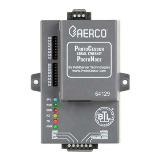
For ProtoNode devices
FPC-N34 P/N 64129 & FPC-N35 P/N 64130,
see OMM-0107.
Disclaimer
The information contained in this manual is subject to change without notice
from AERCO International, Inc. AERCO makes no warranty of any kind with
respect to this material, including, but not limited to, implied warranties of
merchantability and fitness for a particular application. AERCO International is
not liable for errors appearing in this manual, not for incidental or
consequential damages occurring in connection with the furnishing,
performance, or use of these materials.
•
OMM-0150_B
5/20/2021
AERCO Serial (RER)
ProtoNode FPC-N34
(Part Number 64168)
AERCO International, Inc. • 100 Oritani Drive • Blauvelt, NY 10913
USA: T: (845) 580-8000 • Toll Free: (800) 526-0288 • AERCO.com
Technical Support • (800) 526-0288 • Mon-Fri, 8 am - 5 pm EST
AERCO LonWorks (LER)
ProtoNode FPC-N35
(Part Number 64169)
Heating and Hot Water Solutions
© 2021 AERCO
Advertisement
Table of Contents

Subscribe to Our Youtube Channel
Related Manuals for Watts Aerco ProtoNode FPC-N34


Summary of Contents for Watts Aerco ProtoNode FPC-N34
- Page 1 User Manual ProtoNode FPC-N34 FPC-N35 User Manual For interfacing with the following AERCO products: • AM Series • C-More and Edge Controllers • Modulex • ECS/SmartPlate • BMS/BMSII/ACS For interfacing with the following Building Automation Systems: • BACnet MS/TP • BACnet/IP •...
- Page 2 ProtoNode FPC-N34 & FPC-N35 User Manual USER MANUAL The BTL Mark on ProtoNode FPC-N34 is a symbol that indicates that a product has passed a series of rigorous tests conducted by an independent laboratory which verifies that the product correctly implements the BACnet features claimed in the listing.
-
Page 3: Table Of Contents
ProtoNode FPC-N34 & FPC-N35 User Manual USER MANUAL TABLE OF CONTENTS Quick Start Guide ................................. 6 CHAPTER 1. Introduction ..........................7 1.1 ProtoNode Gateway .........................7 CHAPTER 2. BACnet/LonWorks Setup for ProtoNode FPC-N34/FPC-N35 ......11 2.1 Record Identification Data ...................... 11 2.2 Point Count Capacity and Registers per Device .............. - Page 4 ProtoNode FPC-N34 & FPC-N35 User Manual USER MANUAL Encryption ..........................38 5.4 Lost or Incorrect IP Address ....................39 5.5 Change User Management Settings ..................39 CHAPTER 6. BACnet MS/TP and BACnet/IP: Setting Node_Offset to Assign Specific Device Instances ..............................41 CHAPTER 7.
- Page 5 ProtoNode FPC-N34 & FPC-N35 User Manual USER MANUAL Appendix E-5: LED Diagnostics for Modbus RTU Communications Between ProtoNode and Devices ........................... 115 Appendix E-6: Passwords ......................116 Appendix F: C-MORE STATUS AND FAULT MESSAGES ..............117 Appendix G: CONVERSION EQUATIONS FOR TEMPERATURE VARIABLES ......... 123 APPENDIX H: BCM AND BMM FAULT CODES FOR MODULEX E8 CONTROLLER ......
-
Page 6: Quick Start Guide
ProtoNode FPC-N34 & FPC-N35 User Manual USER MANUAL Quick Start Guide • Auto-Discovery connection points are limited by available memory in the device. • Auto-Discovery is not available in SSD mode required for BST (Boiler Sequencing Technology) and WHM (Water Heater Management). •... -
Page 7: Chapter 1. Introduction
ProtoNode FPC-N34 & FPC-N35 User Manual CHAPTER 1 – Introduction CHAPTER 1. INTRODUCTION 1.1 ProtoNode Gateway ProtoNode is an external, high performance Building Automation multi-protocol gateway that is preconfigured to Auto-Discover any AERCO products (hereafter called a “device”) connected to the ProtoNode and automatically configure them for BACnet® MS/TP, BACnet/IP, Metasys®... - Page 8 ProtoNode FPC-N34 & FPC-N35 User Manual CHAPTER 1 – Introduction AERCO’s multi-protocol communications gateway supports integration of AERCO devices with customers’ building control and energy management systems. The plug-n-play package supports integration with BACnet/IP, BACnet MS/TP, LonWorks, and Johnson Controls Metasys N2 systems and Modbus TCP.
- Page 9 ProtoNode FPC-N34 & FPC-N35 User Manual CHAPTER 1 – Introduction AERCO’s Communications Gateway (ProtoNode) is an external, high performance, Building Automation multi-protocol gateway that has been preprogrammed for AERCO’s equipment to support BACnet® MS/TP, BACnet/IP, Metasys® N2 by JCI, Modbus TCP, and LonWorks® All the different AERCO configurations for the various protocols are stored within the ProtoNode and are selectable via DIP switches for fast and easy installation.
- Page 10 ProtoNode FPC-N34 & FPC-N35 User Manual CHAPTER 1 – Introduction (This Page Left Intentionally Blank) • Technical Support • (800) 526-0288 • Mon-Fri, 8 am - 5 pm EST OMM-0150_B 5/20/2021 Page 10 of 140...
-
Page 11: Chapter 2. Bacnet/Lonworks Setup For Protonode Fpc-N34/Fpc-N35
ProtoNode FPC-N34 & FPC-N35 User Manual CHAPTER 2 – BACnet/LonWorks Setup CHAPTER 2. BACNET/LONWORKS SETUP FOR PROTONODE FPC-N34/FPC-N35 2.1 Record Identification Data Each ProtoNode has a unique part number located on the side or the back of the unit. This number should be recorded, as it may be required for technical support. -
Page 12: Configuring Device Communications
ProtoNode FPC-N34 & FPC-N35 User Manual CHAPTER 2 – BACnet/LonWorks Setup 2.3 Configuring Device Communications 2.3.1 Set Modbus COM setting on all of the Devices connected to the ProtoNode • All of the Serial devices connected to ProtoNode MUST have the same Baud Rate, Data Bits, Stop Bits, and Parity settings. -
Page 13: Enabling Auto-Discovery (Not Used On Bst, Whm Or Mfc)
ProtoNode FPC-N34 & FPC-N35 User Manual CHAPTER 2 – BACnet/LonWorks Setup S0 S1 S2 S3 S0 S1 S2 S3 S0 – S3 DIP Switches S Bank DIP Switch Location ProtoNode FPC-N34 S Bank DIP Switches Profile BACnet/IP BACnet MS/TP Metasys N2 Modbus TCP/IP or Modbus RTU *Modbus to 16 WHM/BST Units + 6 SP Units... -
Page 14: Manually Selecting Your Equipment
ProtoNode FPC-N34 & FPC-N35 User Manual CHAPTER 2 – BACnet/LonWorks Setup • After Auto-Discovery is complete, turn off S3 to save the configuration. S3 DIP Switch Auto-Discovery Mode Auto-Discovery ON – Build New Configuration Auto-Discover OFF – Save Current Configuration Figure 2-6: S3 DIP Switch setting for Auto Discovering Devices 2.4.3 Manually Selecting Your Equipment A laptop or PC is required to do this. -
Page 15: Bacnet Ms/Tp And Bacnet/Ip (Fpc-N34): Setting The Device Instance
ProtoNode FPC-N34 & FPC-N35 User Manual CHAPTER 2 – BACnet/LonWorks Setup • Set the BACnet MS/TP MAC addresses of the ProtoNode to a value between 1 to 127 (MAC Master Addresses); this is so that the BMS Front End can find the ProtoNode via BACnet auto discovery. -
Page 16: Metasys N2 Or Modbus Tcp/Ip (Fpc-N34): Setting The Node-Id
ProtoNode FPC-N34 & FPC-N35 User Manual CHAPTER 2 – BACnet/LonWorks Setup BACnet MS/TP or BACnet/IP: Assigning Specific Device Instances 2.5.2.1 With the default Node_Offset value of 50,000 the Device Instances values generated will be within the range of 50,001 to 50,127. •... -
Page 17: Chapter 3. Interfacing Protonode To Devices
ProtoNode FPC-N34 & FPC-N35 User Manual CHAPTER 3 – Interfacing ProtoNode to Devices CHAPTER 3. INTERFACING PROTONODE TO DEVICES 3.1 ProtoNode FPC-N34 and FPC-N35 Showing Connection Ports RS-485 Connector RS-485 RX/TX Field LED Field Port for B.A.S. Bias Resistor Switch Sys/Config Error End of Line Termination Switch... - Page 18 ProtoNode FPC-N34 & FPC-N35 User Manual CHAPTER 3 – Interfacing ProtoNode to Devices Figure 3-1b: LonWorks ProtoNode FPC-N35 (P/N 64169) • Technical Support • (800) 526-0288 • Mon-Fri, 8 am - 5 pm EST OMM-0150_B 5/20/2021 Page 18 of 140...
-
Page 19: Device Connections To Protonode
ProtoNode FPC-N34 & FPC-N35 User Manual CHAPTER 3 – Interfacing ProtoNode to Devices 3.2 Device Connections to ProtoNode ProtoNode 6 Pin Phoenix connector for RS-485 Devices • The 6 pin Phoenix connector is the same for ProtoNode FPC-N34 and FPC-N35. •... -
Page 20: Biasing The Modbus Rs-485 Device Network
ProtoNode FPC-N34 & FPC-N35 User Manual CHAPTER 3 – Interfacing ProtoNode to Devices 3.2.1 Biasing the Modbus RS-485 Device Network • An RS-485 network with more than one device needs to have biasing to ensure proper communication. The biasing only needs to be done on one device. •... -
Page 21: End Of Line Termination Jumper For The Modbus Rs-485 Device Network
ProtoNode FPC-N34 & FPC-N35 User Manual CHAPTER 3 – Interfacing ProtoNode to Devices 3.2.2 End of Line Termination Jumper for the Modbus RS-485 Device Network • On long RS-485 cabling runs, the RS-485 trunk must be properly terminated at each end. •... -
Page 22: Bacnet Ms/Tp, Modbus Rtu Or Metasys N2 (Fpc-N34): Wiring Field Port To Rs-485 Bas Network
ProtoNode FPC-N34 & FPC-N35 User Manual CHAPTER 3 – Interfacing ProtoNode to Devices 3.3 BACnet MS/TP, Modbus RTU or Metasys N2 (FPC-N34): Wiring Field Port to RS-485 BAS Network • Connect the BACnet MS/TP or Metasys N2 RS-485 network wires to the 3-pin RS-485 connector on ProtoNode FPC-N34 as shown below in Figure 3-5. -
Page 23: Lonworks (Fpc-N35): Wiring Field Port To Lonworks Network
ProtoNode FPC-N34 & FPC-N35 User Manual CHAPTER 3 – Interfacing ProtoNode to Devices 3.4 LonWorks (FPC-N35): Wiring Field Port to LonWorks Network • Connect ProtoNode to the field network with the LonWorks terminal using a twisted pair non-shielded cable. LonWorks has no polarity. Figure 3-7: LonWorks Terminal 3.5 ACS/BMS II Wiring Connections to ProtoNode FPC-N34 and FPC- •... -
Page 24: Modulex Bcm Connections
ProtoNode FPC-N34 & FPC-N35 User Manual CHAPTER 3 – Interfacing ProtoNode to Devices Figure 3-8: RS-232 Connection to BMS Figure 3-9: RS-232 Connection to ACS/BMS II 3.5.1 Modulex BCM Connections Figure 3-10: RS-485 Connection to BCM • Technical Support • (800) 526-0288 • Mon-Fri, 8 am - 5 pm EST OMM-0150_B 5/20/2021 Page 24 of 140... -
Page 25: Ecs/Sp Connections
ProtoNode FPC-N34 & FPC-N35 User Manual CHAPTER 3 – Interfacing ProtoNode to Devices 3.5.2 ECS/SP Connections Connect ECS/SP terminals HE and HF to XPC Port 1a as follows: • Connect the “HF” terminal to the ProtoNode’s “RS485 +” port • Connect the “HE”... -
Page 26: Am Series Connections
ProtoNode FPC-N34 & FPC-N35 User Manual CHAPTER 3 – Interfacing ProtoNode to Devices 3.5.4 AM Series Connections Figure 3-13: RS-485 Connection to AM Series (RS-485) NOTE: For connection of the ProtoNode along with the AERCO AM Series Cascade Sequencer Controller, see Appendix I. •... -
Page 27: Mfc 3000 / 4000 / 5000 / 6000 Connections
ProtoNode FPC-N34 & FPC-N35 User Manual CHAPTER 3 – Interfacing ProtoNode to Devices 3.6 MFC 3000 / 4000 / 5000 / 6000 Connections Figure 3-14: RS-485 Connection to MFC 3000 / 4000 / 5000 / 6000 Figure 3-15: RS-232 Connection to MFC 8000 / 10000 •... -
Page 28: Power-Up Protonode
ProtoNode FPC-N34 & FPC-N35 User Manual CHAPTER 3 – Interfacing ProtoNode to Devices 3.7 Power-Up ProtoNode Apply power to ProtoNode as shown below in Figure 3-15 Ensure that the power supply used complies with the specifications provided in Appendix J-1. •... -
Page 29: Auto-Discovery: After Completion - Turn Off To Save Configuration
ProtoNode FPC-N34 & FPC-N35 User Manual CHAPTER 3 – Interfacing ProtoNode to Devices 3.7.1 Auto-Discovery: After Completion – Turn Off to Save Configuration The S3 DIP switch for Enabling Auto-Discovery should have been set in Section 2.4.2 before applying power to the ProtoNode. Do not Enable Auto-Discovery when the unit is powered. •... - Page 30 ProtoNode FPC-N34 & FPC-N35 User Manual CHAPTER 3 – Interfacing ProtoNode to Devices (This page intentionally left blank) • Technical Support • (800) 526-0288 • Mon-Fri, 8 am - 5 pm EST OMM-0150_B 5/20/2021 Page 30 of 140...
-
Page 31: Chapter 4. Bacnet/Ip Or Modbus Tcp/Ip: Change The Protonode Ip Address
ProtoNode FPC-N34 & FPC-N35 User Manual CHAPTER 4 – BACnet/IP or Modbus TCP/IP CHAPTER 4. BACNET/IP OR MODBUS TCP/IP: CHANGE THE PROTONODE IP ADDRESS 4.1 Connect the PC to ProtoNode via the Ethernet Port • Connect a CAT5 Ethernet cable (Straight through or Cross-Over) between the PC and ProtoNode. -
Page 32: Bacnet/Ip And Modbus Tcp/Ip: Setting Ip Address For Field Network
ProtoNode FPC-N34 & FPC-N35 User Manual CHAPTER 4 – BACnet/IP or Modbus TCP/IP • Click on the Use the following IP address radio button and type in the IP Address. • Click the OK button twice to complete the process. 4.2 BACnet/IP and Modbus TCP/IP: Setting IP Address for Field Network •... - Page 33 ProtoNode FPC-N34 & FPC-N35 User Manual CHAPTER 4 – BACnet/IP or Modbus TCP/IP Figure 4-2: Changing IP Address via Web GUI • From the Web GUI’s landing page, click on Setup to expand the navigation tree and then select Network Settings to access the IP Settings menu (Figure 4-2). •...
- Page 34 ProtoNode FPC-N34 & FPC-N35 User Manual CHAPTER 4 – BACnet/IP or Modbus TCP/IP (This page intentionally left blank) • Technical Support • (800) 526-0288 • Mon-Fri, 8 am - 5 pm EST OMM-0150_B 5/20/2021 Page 34 of 140...
-
Page 35: Chapter 5. Setup Web Server Security
ProtoNode FPC-N34 & FPC-N35 User Manual CHAPTER 5 – Setup Web Server Security CHAPTER 5. SETUP WEB SERVER SECURITY Navigate to the IP Address of the ProtoNode on the local PC by opening a web browser and entering the IP Address of the ProtoNode; the default Ethernet address is 192.168.1.24. NOTE: If the IP Address of the ProtoNode was changed, the assigned IP Address can be discovered using the FS Toolbox utility. - Page 36 ProtoNode FPC-N34 & FPC-N35 User Manual CHAPTER 5 – Setup Web Server Security • Additional text will expand below the warning, click the underlined text to go to the IP Address. In Error! Reference source not found.5-3, this text is “Proceed to 10.40.50.94 (unsafe)”.
-
Page 37: Select The Security Mode
ProtoNode FPC-N34 & FPC-N35 User Manual CHAPTER 5 – Setup Web Server Security 5.2 Select the Security Mode On the first login to the FieldServer, the following screen will appear that allows the user to select which mode the FieldServer should use. Figure 5-5: Security Mode Selection Screen NOTES: Cookies are used for authentication. -
Page 38: Encryption
ProtoNode FPC-N34 & FPC-N35 User Manual CHAPTER 5 – Setup Web Server Security Figure 5-6: Security Mode Selection Screen – Certificate & Private Key 1. Copy and paste the Certificate and Private Key text into their respective fields. If the Private Key is encrypted type in the associated Passphrase. -
Page 39: Lost Or Incorrect Ip Address
ProtoNode FPC-N34 & FPC-N35 User Manual CHAPTER 5 – Setup Web Server Security 5.4 Lost or Incorrect IP Address • Ensure that FieldServer Toolbox is loaded onto the local PC. Otherwise, download the FieldServer-Toolbox.zip via the MSA Safety website. • Extract the executable file and complete the installation. - Page 40 ProtoNode FPC-N34 & FPC-N35 User Manual CHAPTER 5 – Setup Web Server Security (This page intentionally left blank) • Technical Support • (800) 526-0288 • Mon-Fri, 8 am - 5 pm EST OMM-0150_B 5/20/2021 Page 40 of 140...
-
Page 41: Chapter 6. Bacnet Ms/Tp And Bacnet/Ip: Setting Node_Offset To Assign Specific Device Instances
ProtoNode FPC-N34 & FPC-N35 User Manual CHAPTER 6 – BACnet MS/TP and BACnet/IP CHAPTER 6. BACNET MS/TP AND BACNET/IP: SETTING NODE_OFFSET TO ASSIGN SPECIFIC DEVICE INSTANCES • After setting your PC to be on the same subnet as the ProtoNode (Section 4.1 ), open a web browser on your PC and enter the IP Address of the ProtoNode;... - Page 42 ProtoNode FPC-N34 & FPC-N35 User Manual CHAPTER 6 – BACnet MS/TP and BACnet/IP Figure 6-1: Web Configurator screen • Technical Support • (800) 526-0288 • Mon-Fri, 8 am - 5 pm EST OMM-0150_B 5/20/2021 Page 42 of 140...
-
Page 43: Chapter 7. How To Start The Installation Over: Clearing Profiles
ProtoNode FPC-N34 & FPC-N35 User Manual CHAPTER 7 – How to Start The Installation Over: Clearing Profiles CHAPTER 7. HOW TO START THE INSTALLATION OVER: CLEARING PROFILES • After setting your PC to be on the same subnet as the ProtoNode (Section 4.1 ), open a web browser on your PC and enter the IP Address of the ProtoNode;... - Page 44 ProtoNode FPC-N34 & FPC-N35 User Manual CHAPTER 7 – How to Start The Installation Over: Clearing Profiles (This page intentionally left blank) • Technical Support • (800) 526-0288 • Mon-Fri, 8 am - 5 pm EST OMM-0150_B 5/20/2021 Page 44 of 140...
-
Page 45: Chapter 8. Lonworks (Fpc-N35): Commissioning Protonode On A Lonworks Network45
ProtoNode FPC-N34 & FPC-N35 User Manual CHAPTER 8 – LonWorks (FPC-N35) Commissioning ProtoNode CHAPTER 8. LONWORKS (FPC-N35): COMMISSIONING PROTONODE ON A LONWORKS NETWORK Commissioning may only be performed by the LonWorks administrator. 8.1 Commissioning ProtoNode FPC-N35 on a LonWorks Network The User will be prompted by the LonWorks Administrator to hit the Service Pin on the ProtoNode FPC-N35 at the correct step of the Commissioning process which is different for each LonWorks Network Management Tool. - Page 46 ProtoNode FPC-N34 & FPC-N35 User Manual CHAPTER 8 – LonWorks (FPC-N35) Commissioning ProtoNode 2. If the Control Panel is displayed by category, click Network and Internet and then choose Network and Sharing Center. If the Control Panel is displayed by icon, choose Network and Sharing Center. 3.
- Page 47 ProtoNode FPC-N34 & FPC-N35 User Manual CHAPTER 8 – LonWorks (FPC-N35) Commissioning ProtoNode Figure 8-2: Sample of Fserver.XIF File Being Generated • Technical Support • (800) 526-0288 • Mon-Fri, 8 am - 5 pm EST OMM-0150_B 5/20/2021 Page 47 of 140...
- Page 48 ProtoNode FPC-N34 & FPC-N35 User Manual CHAPTER 8 – LonWorks (FPC-N35) Commissioning ProtoNode (This page intentionally left blank) • Technical Support • (800) 526-0288 • Mon-Fri, 8 am - 5 pm EST OMM-0150_B 5/20/2021 Page 48 of 140...
-
Page 49: Chapter 9. Cas Bacnet Explorer For Validating Protonode In The Field
ProtoNode FPC-N34 & FPC-N35 User Manual CHAPTER 9 – CAS BACNET EXPLORER CHAPTER 9. CAS BACNET EXPLORER FOR VALIDATING PROTONODE IN THE FIELD Sierra Monitor has arranged a complementary 2 week fully functional copy of CAS BACnet Explorer (through Chipkin Automation) that can be used to validate BACnet MS/TP and/or BACnet/IP communications of ProtoNode in the field without having to have the BAS Integrator on site. -
Page 50: Cas Bacnet Setup
ProtoNode FPC-N34 & FPC-N35 User Manual CHAPTER 9 – CAS BACNET EXPLORER • Open CAS BACnet Explorer; in the CAS Activation form, enter the email address that was registered and click on “Request a key”. The CAS key will then be emailed to the registered address. -
Page 51: Cas Bacnet Bacnet/Ip Setup
ProtoNode FPC-N34 & FPC-N35 User Manual CHAPTER 9 – CAS BACNET EXPLORER 9.2.2 CAS BACnet BACnet/IP Setup See Section 4.2 to set the IP Address and subnet of the PC that will be running the CAS Explorer. Connect a straight through or cross Ethernet cable from the PC to ProtoNode. In CAS Explorer, do the following: o Click on “settings”... - Page 52 ProtoNode FPC-N34 & FPC-N35 User Manual CHAPTER 9 – CAS BACNET EXPLORER (This Page Left Intentionally Blank) • Technical Support • (800) 526-0288 • Mon-Fri, 8 am - 5 pm EST OMM-0150_B 5/20/2021 Page 52 of 140...
-
Page 53: Appendix A: "A" Bank Dip Switch Settings
ProtoNode FPC-N34 & FPC-N35 User Manual APPENDIX A: “A” BANK DIP SWITCH SETTINGS “A” BANK DIP SWITCH SETTINGS APPENDIX A: “A” Bank DIP Switch Settings Address Address • Technical Support • (800) 526-0288 • Mon-Fri, 8 am - 5 pm EST OMM-0150_B 5/20/2021 Page 53 of 140... - Page 54 ProtoNode FPC-N34 & FPC-N35 User Manual APPENDIX A: “A” BANK DIP SWITCH SETTINGS Address Address • Technical Support • (800) 526-0288 • Mon-Fri, 8 am - 5 pm EST OMM-0150_B 5/20/2021 Page 54 of 140...
- Page 55 ProtoNode FPC-N34 & FPC-N35 User Manual APPENDIX A: “A” BANK DIP SWITCH SETTINGS Address Address • Technical Support • (800) 526-0288 • Mon-Fri, 8 am - 5 pm EST OMM-0150_B 5/20/2021 Page 55 of 140...
- Page 56 ProtoNode FPC-N34 & FPC-N35 User Manual APPENDIX A: “A” BANK DIP SWITCH SETTINGS (This Page Left Intentionally Blank) • Technical Support • (800) 526-0288 • Mon-Fri, 8 am - 5 pm EST OMM-0150_B 5/20/2021 Page 56 of 140...
-
Page 57: Appendix B: Aerco Equipment Monitor And Control Point Definitions
ProtoNode FPC-N34 & FPC-N35 User Manual APPENDIX B: EQUIPMENT MONITOR AND CONTROL POINT DEFINITIONS APPENDIX B: AERCO EQUIPMENT MONITOR AND CONTROL POINT DEFINITIONS Definitions of the monitor and control points associated with the AERCO Equipment Configurations are provided in the tables below. Appendix B-1: AERCO C-More &... - Page 58 ProtoNode FPC-N34 & FPC-N35 User Manual APPENDIX B: EQUIPMENT MONITOR AND CONTROL POINT DEFINITIONS Appendix B-1: AERCO C-More & ACS/BMS II/BMS Point Definitions GF-108, GF- Modbus Data BAS Modbus Reg. Point Name 124, GF-114 Address Units (Range) Data Address Type Point Name (Hex/Dec.) Bit (0 to 65535)
- Page 59 ProtoNode FPC-N34 & FPC-N35 User Manual APPENDIX B: EQUIPMENT MONITOR AND CONTROL POINT DEFINITIONS Appendix B-1: AERCO C-More & ACS/BMS II/BMS Point Definitions GF-108, GF- Modbus Data BAS Modbus Reg. Point Name 124, GF-114 Address Units (Range) Data Address Type Point Name (Hex/Dec.) Net Blr 8 Status...
-
Page 60: Appendix B-2: Aerco Electronic Control System (Ecs) Point Definitions
ProtoNode FPC-N34 & FPC-N35 User Manual APPENDIX B: EQUIPMENT MONITOR AND CONTROL POINT DEFINITIONS Appendix B-2: AERCO Electronic Control System (ECS) Point Definitions Modbus GF-108, GF- Point Modbus Reg. Data 124, GF-114 Units (Range) Name Data Type Address Point Name Address (Hex/Dec.) Electric Valve (ECS) and SmartPlate... -
Page 61: Appendix B-3: Aerco (Modulex) Bcm Point Definitions
ProtoNode FPC-N34 & FPC-N35 User Manual APPENDIX B: EQUIPMENT MONITOR AND CONTROL POINT DEFINITIONS Alarm 7 Out AV: 10345 nvoSPEVAlarm7Out_XXX SNVT_count_f Input 10345 Alarm 8 Out AV: 10361 nvoSPEVAlarm8Out_XXX SNVT_count_f Input 10361 Appendix B-3: AERCO (Modulex) BCM Point Definitions Appendix B-3: AERCO (Modulex) BCM Point Definitions GF-108, GF- Modbus Data BAS Modbus... - Page 62 ProtoNode FPC-N34 & FPC-N35 User Manual APPENDIX B: EQUIPMENT MONITOR AND CONTROL POINT DEFINITIONS IMPORTANT: Some Modbus addresses specified in this manual are written generically in hexadecimal/decimal format. However, many Building Automation Systems utilize another form of addressing where: • 40001 is added to the generic address for a Holding Register address.
-
Page 63: Appendix B-4: Water Heater Management System (Whm) And On-Board Boiler Sequencing Technology (Bst) Point Definitions
ProtoNode FPC-N34 & FPC-N35 User Manual APPENDIX B: EQUIPMENT MONITOR AND CONTROL POINT DEFINITIONS Appendix B-4: Water Heater Management System (WHM) and On-Board Boiler Sequencing Technology (BST) Point Definitions Appendix B-4: AERCO WHM and BST Point Definitions Modbus Modbus Reg. Data GF-108, GF-124, GF-114 Point Name... - Page 64 ProtoNode FPC-N34 & FPC-N35 User Manual APPENDIX B: EQUIPMENT MONITOR AND CONTROL POINT DEFINITIONS Appendix B-4: AERCO WHM and BST Point Definitions Modbus Modbus Reg. Data GF-108, GF-124, GF-114 Point Name Units (Range) Point Name Data Type Address Address (Dec.) More fault codes.
- Page 65 ProtoNode FPC-N34 & FPC-N35 User Manual APPENDIX B: EQUIPMENT MONITOR AND CONTROL POINT DEFINITIONS SmartPlate EV Points as a part of BST: Modbus Modbus BACnet Point Name Lon Name Lon SNVT Reg. Data Units (Range) Address Type Address SNVT_count_inc SP Outlet AV: xx00 nvoSPHTR_yy_1 Input...
- Page 66 ProtoNode FPC-N34 & FPC-N35 User Manual APPENDIX B: EQUIPMENT MONITOR AND CONTROL POINT DEFINITIONS Unit Types for Boilers /Water Heaters C-More Units Edge Units 1 = KC Boiler LN 0 = KC Boiler 2 = BMK Boiler Std 1 = KC Boiler LN 3 = BMK Blr Std Dual 2 = BMK Boiler Std 4 = BMK Boiler LN...
-
Page 67: Appendix B-5: Am Series Point Definitions
ProtoNode FPC-N34 & FPC-N35 User Manual APPENDIX B: EQUIPMENT MONITOR AND CONTROL POINT DEFINITIONS Appendix B-5: AM Series Point Definitions For all devices, empty or not, available holding registers return 0. When it is not implemented, requests can be ignored by the Modbus device. Holding registers below 99 are reserved for legacy devices, and are optional. - Page 68 ProtoNode FPC-N34 & FPC-N35 User Manual APPENDIX B: EQUIPMENT MONITOR AND CONTROL POINT DEFINITIONS Appendix B-5 Table 1: AM Managing Boiler Parameters Holding Access Automatic Parameter Name Range Register Conversion Bit0: On/Off - Flame Signal Bit1: Ok/Nok - Water level Bit2: Ok/Nok - Low gas pressure Information: 007B...
- Page 69 ProtoNode FPC-N34 & FPC-N35 User Manual APPENDIX B: EQUIPMENT MONITOR AND CONTROL POINT DEFINITIONS Appendix B-5 Table 2: AM Controller (Managing) Parameters Access Holding Automatic Parameter Name Range Register Conversion 00D1 Maximum Outdoor air setpoint Depending on units °C / °F 00D2 Outdoor air shutdown temperature Depending on units °C / °F...
- Page 70 ProtoNode FPC-N34 & FPC-N35 User Manual APPENDIX B: EQUIPMENT MONITOR AND CONTROL POINT DEFINITIONS Appendix B-5 Table 3: AM Dependent Boiler Parameters Access Holding Automatic Parameter Name Range Register Conversion 117 0075 Firing Rate 0..100% 118 0076 Min Firing Rate 0..100% 119 0077 Flame current...
-
Page 71: Appendix C: Aerco Equipment Point Mappings
ProtoNode FPC-N34 & FPC-N35 User Manual APPENDIX C: AERCO EQUIPMENT POINT MAPPINGS Appendix C: AERCO EQUIPMENT POINT MAPPINGS Appendix C-1: AM Mngr Modbus RTU Mappings to BACnet MS/TP, BACnet/IP, Metasys N2, Modbus TCP/IP and LonWorks Single Node Option: The ProtoNode will be discovered as one device and each boiler will show a different range of AV addresses, depending on their Unit or “Comm”... - Page 72 ProtoNode FPC-N34 & FPC-N35 User Manual APPENDIX C: AERCO EQUIPMENT POINT MAPPINGS Appendix C-1: AM Mngr Modbus RTU Mappings to BACnet MS/TP, BACnet/IP, Metasys N2, Modbus TCP/IP and LonWorks BACnet BACnet N2 Point Modbus Name / Point Name Object Object Data Lon Name Lon SNVT...
- Page 73 ProtoNode FPC-N34 & FPC-N35 User Manual APPENDIX C: AERCO EQUIPMENT POINT MAPPINGS Appendix C-1: AM Mngr Modbus RTU Mappings to BACnet MS/TP, BACnet/IP, Metasys N2, Modbus TCP/IP and LonWorks BACnet BACnet N2 Point Modbus Name / Point Name Object Object Data Lon Name Lon SNVT...
- Page 74 ProtoNode FPC-N34 & FPC-N35 User Manual APPENDIX C: AERCO EQUIPMENT POINT MAPPINGS Appendix C-1: AM Mngr Modbus RTU Mappings to BACnet MS/TP, BACnet/IP, Metasys N2, Modbus TCP/IP and LonWorks BACnet BACnet N2 Point Modbus Name / Point Name Object Object Data Lon Name Lon SNVT...
-
Page 75: Appendix C-2: Am Dep Modbus Rtu Mappings To Bacnet Ms/Tp, Bacnet/Ip, Metasys N2, Modbus Tcp/Ip And Lonworks
ProtoNode FPC-N34 & FPC-N35 User Manual APPENDIX C: AERCO EQUIPMENT POINT MAPPINGS Appendix C-2: AM Dep Modbus RTU Mappings to BACnet MS/TP, BACnet/IP, Metasys N2, Modbus TCP/IP and LonWorks Appendix C-2: AM Dep Modbus RTU Mappings to BACnet MS/TP, BACnet/IP, Metasys N2, Modbus TCP/IP and LonWorks BACnet BACnet N2 Point... - Page 76 ProtoNode FPC-N34 & FPC-N35 User Manual APPENDIX C: AERCO EQUIPMENT POINT MAPPINGS Appendix C-2: AM Dep Modbus RTU Mappings to BACnet MS/TP, BACnet/IP, Metasys N2, Modbus TCP/IP and LonWorks BACnet BACnet N2 Point Modbus Name / Point Name Object Object Data Lon Name Lon SNVT...
-
Page 77: Appendix C-3: C-More Modbus Rtu Mappings To Bacnet Ms/Tp, Bacnet/Ip, Metasys N2, Modbus Tcp/Ip And Lonworks
ProtoNode FPC-N34 & FPC-N35 User Manual APPENDIX C: AERCO EQUIPMENT POINT MAPPINGS Appendix C-3: C-More Modbus RTU Mappings to BACnet MS/TP, BACnet/IP, Metasys N2, Modbus TCP/IP and LonWorks Appendix C-3: C-More Modbus RTU Mappings to BACnet MS/TP, BACnet/IP, Metasys N2, Modbus TCP/IP and LonWorks BACnet BACnet N2 Point... -
Page 78: Appendix C-5: Ecs/Sp Modbus Rtu Mappings To Bacnet Ms/Tp, Bacnet/Ip, Metasys N2, Modbus Tcp/Ip And Lonworks
ProtoNode FPC-N34 & FPC-N35 User Manual APPENDIX C: AERCO EQUIPMENT POINT MAPPINGS Appendix C-4: Modulex Modbus RTU Mappings to BACnet MS/TP, BACnet/IP, Metasys N2, Modbus TCP/IP and LonWorks BACnet BACnet N2 Point Modbus Name Point Name Object Object Data Lon Name Lon SNVT Address Address... -
Page 79: Appendix C-6: Acs/Bmsii/Bms Modbus Rtu Mappings To Bacnet Ms/Tp, Bacnet/Ip, Metasys N2, Modbus Tcp/Ip And Lonworks
ProtoNode FPC-N34 & FPC-N35 User Manual APPENDIX C: AERCO EQUIPMENT POINT MAPPINGS Appendix C-6: ACS/BMSII/BMS Modbus RTU Mappings to BACnet MS/TP, BACnet/IP, Metasys N2, Modbus TCP/IP and LonWorks Appendix C-6: ACS/BMSII/BMS Modbus RTU Mappings to BACnet MS/TP, BACnet/IP, Metasys N2, Modbus TCP/IP and LonWorks BACnet BACnet N2 Point... - Page 80 ProtoNode FPC-N34 & FPC-N35 User Manual APPENDIX C: AERCO EQUIPMENT POINT MAPPINGS Appendix C-6: ACS/BMSII/BMS Modbus RTU Mappings to BACnet MS/TP, BACnet/IP, Metasys N2, Modbus TCP/IP and LonWorks BACnet BACnet N2 Point Modbus Name Point Name Object Object Data Lon Name Lon SNVT Address Address...
-
Page 81: Appendix C-7: Mfc Lmv5 Points
ProtoNode FPC-N34 & FPC-N35 User Manual APPENDIX C: AERCO EQUIPMENT POINT MAPPINGS Appendix C-7: MFC LMV5 Points FPC-N34 FPC-N35 Modbus Point Name BACnet BACnet N2 Data N2 Point Address Lon Name Lon SNVT Type Data Type Object Id Type Address Phase nvoPhase_XXX SNVT_count_inc_f... - Page 82 ProtoNode FPC-N34 & FPC-N35 User Manual APPENDIX C: AERCO EQUIPMENT POINT MAPPINGS FPC-N34 FPC-N35 Modbus Point Name BACnet BACnet N2 Data N2 Point Address Lon Name Lon SNVT Type Data Type Object Id Type Address Flue gas temp nvoFluGasTmp_XXX SNVT_count_inc_f 40032 Combustion efficiency nvoComEff_XXX...
- Page 83 ProtoNode FPC-N34 & FPC-N35 User Manual APPENDIX C: AERCO EQUIPMENT POINT MAPPINGS FPC-N34 FPC-N35 Modbus Point Name BACnet BACnet N2 Data N2 Point Address Lon Name Lon SNVT Type Data Type Object Id Type Address power Startup counter gas nvi/nvoStCntGas_XXX SNVT_count_inc_f 40071, 40072 Startup counter oil...
- Page 84 ProtoNode FPC-N34 & FPC-N35 User Manual APPENDIX C: AERCO EQUIPMENT POINT MAPPINGS FPC-N34 FPC-N35 Modbus Point Name BACnet BACnet N2 Data N2 Point Address Lon Name Lon SNVT Type Data Type Object Id Type Address Brnr Ctrl id date Reg 1 nvoBrnIDDtR1_XXX SNVT_count_inc_f 40109...
- Page 85 ProtoNode FPC-N34 & FPC-N35 User Manual APPENDIX C: AERCO EQUIPMENT POINT MAPPINGS FPC-N34 FPC-N35 Modbus Point Name BACnet BACnet N2 Data N2 Point Address Lon Name Lon SNVT Type Data Type Object Id Type Address Current Lockout Error diagnostics nvoCrLkErDig_XXX SNVT_count_inc_f 40402 Current Lockout Error class...
-
Page 86: Appendix C-8: Mfc Rwf55 Points
ProtoNode FPC-N34 & FPC-N35 User Manual APPENDIX C: AERCO EQUIPMENT POINT MAPPINGS Appendix C-8: MFC RWF55 Points FPC-N34 FPC-N35 Modbus Point Name N2 Point BACnet Data BACnet N2 Data Address Lon Name Lon SNVT Type Address Type Object Id Type INPUT 1 X1 nvoX1_XXX SNVT_count_inc_f... - Page 87 ProtoNode FPC-N34 & FPC-N35 User Manual APPENDIX C: AERCO EQUIPMENT POINT MAPPINGS FPC-N34 FPC-N35 Modbus Point Name N2 Point BACnet Data BACnet N2 Data Address Lon Name Lon SNVT Type Address Type Object Id Type ACTUAL OUTPUT Y nvoActOutY_XXX SNVT_count_inc_f 44164 BURNER ALARM nvoBrnAlm_XXX...
- Page 88 ProtoNode FPC-N34 & FPC-N35 User Manual APPENDIX C: AERCO EQUIPMENT POINT MAPPINGS FPC-N34 FPC-N35 Modbus Point Name N2 Point BACnet Data BACnet N2 Data Address Lon Name Lon SNVT Type Address Type Object Id Type HYS5 OFF HYST TOP COOLING HYS6 nvi/nvoHys6_XXX SNVT_count_inc_f...
-
Page 89: Standalone Smartplate Ev Points
ProtoNode FPC-N34 & FPC-N35 User Manual APPENDIX C: AERCO EQUIPMENT POINT MAPPINGS Standalone SmartPlate EV Points: Modbus Modbus BACnet Point Name Lon Name Lon SNVT Data Address Type Address DHW Out AV: 1 nvoSPEVDhwOut_XXX SNVT_count_inc Input Setpoint AV: 2 nviSPEVSetpoint_XXX SNVT_count_inc Holding Valve POS... -
Page 90: Appendix D: Eight C-More Boilers/Heaters And Bst/Whm Master
ProtoNode FPC-N34 & FPC-N35 User Manual APPENDIX D: EIGHT C-MORE BOILERS/HEATERS AND BST/WHM MASTER Appendix D: EIGHT C-MORE BOILERS/HEATERS AND BST/WHM MASTER Appendix D: Eight C-More Boilers/Heaters and BST/WHM Master Read BACnet Modbus Equip Point Name Name N2 Type Lon NAME Lon SNVT Lon Direction Only... - Page 91 ProtoNode FPC-N34 & FPC-N35 User Manual APPENDIX D: EIGHT C-MORE BOILERS/HEATERS AND BST/WHM MASTER Appendix D: Eight C-More Boilers/Heaters and BST/WHM Master Read BACnet Modbus Equip Point Name Name N2 Type Lon NAME Lon SNVT Lon Direction Only Type:ID Address Blr Addr 2 ✓...
- Page 92 ProtoNode FPC-N34 & FPC-N35 User Manual APPENDIX D: EIGHT C-MORE BOILERS/HEATERS AND BST/WHM MASTER Appendix D: Eight C-More Boilers/Heaters and BST/WHM Master Read BACnet Modbus Equip Point Name Name N2 Type Lon NAME Lon SNVT Lon Direction Only Type:ID Address ✓...
- Page 93 ProtoNode FPC-N34 & FPC-N35 User Manual APPENDIX D: EIGHT C-MORE BOILERS/HEATERS AND BST/WHM MASTER Appendix D: Eight C-More Boilers/Heaters and BST/WHM Master Read BACnet Modbus Equip Point Name Name N2 Type Lon NAME Lon SNVT Lon Direction Only Type:ID Address ✓...
- Page 94 ProtoNode FPC-N34 & FPC-N35 User Manual APPENDIX D: EIGHT C-MORE BOILERS/HEATERS AND BST/WHM MASTER Appendix D: Eight C-More Boilers/Heaters and BST/WHM Master Read BACnet Modbus Equip Point Name Name N2 Type Lon NAME Lon SNVT Lon Direction Only Type:ID Address ✓...
- Page 95 ProtoNode FPC-N34 & FPC-N35 User Manual APPENDIX D: EIGHT C-MORE BOILERS/HEATERS AND BST/WHM MASTER Appendix D: Eight C-More Boilers/Heaters and BST/WHM Master Read BACnet Modbus Equip Point Name Name N2 Type Lon NAME Lon SNVT Lon Direction Only Type:ID Address ✓...
- Page 96 ProtoNode FPC-N34 & FPC-N35 User Manual APPENDIX D: EIGHT C-MORE BOILERS/HEATERS AND BST/WHM MASTER Appendix D: Eight C-More Boilers/Heaters and BST/WHM Master Read BACnet Modbus Equip Point Name Name N2 Type Lon NAME Lon SNVT Lon Direction Only Type:ID Address ✓...
- Page 97 ProtoNode FPC-N34 & FPC-N35 User Manual APPENDIX D: EIGHT C-MORE BOILERS/HEATERS AND BST/WHM MASTER Appendix D: Eight C-More Boilers/Heaters and BST/WHM Master Read BACnet Modbus Equip Point Name Name N2 Type Lon NAME Lon SNVT Lon Direction Only Type:ID Address ✓...
- Page 98 ProtoNode FPC-N34 & FPC-N35 User Manual APPENDIX D: EIGHT C-MORE BOILERS/HEATERS AND BST/WHM MASTER Appendix D: Eight C-More Boilers/Heaters and BST/WHM Master Read BACnet Modbus Equip Point Name Name N2 Type Lon NAME Lon SNVT Lon Direction Only Type:ID Address ✓...
- Page 99 ProtoNode FPC-N34 & FPC-N35 User Manual APPENDIX D: EIGHT C-MORE BOILERS/HEATERS AND BST/WHM MASTER Appendix D: Eight C-More Boilers/Heaters and BST/WHM Master Read BACnet Modbus Equip Point Name Name N2 Type Lon NAME Lon SNVT Lon Direction Only Type:ID Address ✓...
- Page 100 ProtoNode FPC-N34 & FPC-N35 User Manual APPENDIX D: EIGHT C-MORE BOILERS/HEATERS AND BST/WHM MASTER Appendix D: Eight C-More Boilers/Heaters and BST/WHM Master Read BACnet Modbus Equip Point Name Name N2 Type Lon NAME Lon SNVT Lon Direction Only Type:ID Address ✓...
- Page 101 ProtoNode FPC-N34 & FPC-N35 User Manual APPENDIX D: EIGHT C-MORE BOILERS/HEATERS AND BST/WHM MASTER Appendix D: Eight C-More Boilers/Heaters and BST/WHM Master Read BACnet Modbus Equip Point Name Name N2 Type Lon NAME Lon SNVT Lon Direction Only Type:ID Address ✓...
- Page 102 ProtoNode FPC-N34 & FPC-N35 User Manual APPENDIX D: EIGHT C-MORE BOILERS/HEATERS AND BST/WHM MASTER Appendix D: Eight C-More Boilers/Heaters and BST/WHM Master Read BACnet Modbus Equip Point Name Name N2 Type Lon NAME Lon SNVT Lon Direction Only Type:ID Address ✓...
- Page 103 ProtoNode FPC-N34 & FPC-N35 User Manual APPENDIX D: EIGHT C-MORE BOILERS/HEATERS AND BST/WHM MASTER Appendix D: Eight C-More Boilers/Heaters and BST/WHM Master Read BACnet Modbus Equip Point Name Name N2 Type Lon NAME Lon SNVT Lon Direction Only Type:ID Address ✓...
- Page 104 ProtoNode FPC-N34 & FPC-N35 User Manual APPENDIX D: EIGHT C-MORE BOILERS/HEATERS AND BST/WHM MASTER Appendix D: Eight C-More Boilers/Heaters and BST/WHM Master Read BACnet Modbus Equip Point Name Name N2 Type Lon NAME Lon SNVT Lon Direction Only Type:ID Address ✓...
- Page 105 ProtoNode FPC-N34 & FPC-N35 User Manual APPENDIX D: EIGHT C-MORE BOILERS/HEATERS AND BST/WHM MASTER ✓ Units Active SMD_BAS_IP_OpVal_[7] AV:107 Data Float nvoOpVal_8 inc count (9) Output (non-polled) 30107 ✓ Units Faulted SMD_BAS_IP_OpVal_[8] AV:108 Data Float nvoOpVal_9 inc count (9) Output (non-polled) 30108 ✓...
- Page 106 ProtoNode FPC-N34 & FPC-N35 User Manual APPENDIX D: EIGHT C-MORE BOILERS/HEATERS AND BST/WHM MASTER SmartPlate EV Points as a part of BST: Htr Addr 50: Modbus BACnet Modbus Point Name Lon Name Lon SNVT Data Address Reg. Type Address AV: 3500 SP Outlet nvoSPHTR_50_1 SNVT_count_inc...
- Page 107 ProtoNode FPC-N34 & FPC-N35 User Manual APPENDIX D: EIGHT C-MORE BOILERS/HEATERS AND BST/WHM MASTER Htr Addr 52: BACnet Modbus Modbus Data Point Name Lon Name Lon SNVT Address Reg. Type Address SNVT_count_inc SP Outlet AV: 3700 nvoSPHTR_52_1 Input 33700 SNVT_count_inc SP Valve Position AV: 3701 nvoSPHTR_52_2...
- Page 108 ProtoNode FPC-N34 & FPC-N35 User Manual APPENDIX D: EIGHT C-MORE BOILERS/HEATERS AND BST/WHM MASTER Htr Addr 54: Modbus BACnet Modbus Point Name Lon Name Lon SNVT Data Address Reg. Type Address SNVT_count_inc SP Outlet AV: 3900 nvoSPHTR_54_1 Input 33900 SNVT_count_inc SP Valve Position AV: 3901 nvoSPHTR_54_2...
-
Page 109: Appendix E: Troubleshooting
ProtoNode FPC-N34 & FPC-N35 User Manual APPENDIX E: TROUBLESHOOTING Appendix E: TROUBLESHOOTING Appendix E-1: Viewing Diagnostic Information • Type the IP Address of the ProtoNode into your web browser or use the FieldServer Toolbox to connect to the ProtoNode. • Click on the Diagnostics and Debugging button (see Figure 4-1). -
Page 110: Appendix E-2: Check Wiring And Settings
ProtoNode FPC-N34 & FPC-N35 User Manual APPENDIX E: TROUBLESHOOTING Appendix E-2: Check Wiring and Settings No COMS on Modbus RTU side. If Tx/Rx are not flashing rapidly, then there is a COM issue on the Modbus side and you need to check the following things: o Visual observations of LEDs on ProtoNode (see Appendix E-5) o Check baud rate, parity, data bits, stop bits o Check Modbus device address... -
Page 111: Appendix E-3: Diagnostic Capture With The Fieldserver Utilities
ProtoNode FPC-N34 & FPC-N35 User Manual APPENDIX E: TROUBLESHOOTING Appendix E-3: Diagnostic Capture with the FieldServer Utilities Once the Diagnostic Capture is complete, email it to support@sierramonitor.com. The Diagnostic Capture will allow us to rapidly diagnose the problem. • Ensure that FieldServer Toolbox is Loaded on the PC that is currently being used, or download FieldServer-Toolbox.zip on the Sierra Monitor Corporation webpage, under Customer Care: Resource Center, Software Downloads: http://www.sierramonitor.com/customer-care/resource-center?filters=software-... - Page 112 ProtoNode FPC-N34 & FPC-N35 User Manual APPENDIX E: TROUBLESHOOTING o Select Full Diagnostic. o If desired, the default capture period can be changed. o Click on Start Diagnostic. o Wait for Capture period to finish. The Diagnostic Test Complete window will appear.
- Page 113 ProtoNode FPC-N34 & FPC-N35 User Manual APPENDIX E: TROUBLESHOOTING • Step 2: Send Log o Once the Diagnostic test is complete, a .zip file will be saved on the PC. o Choose open to launch explorer and have it point directly at the correct folder. Send the Diagnostic zip file to support@sierramonitor.com •...
-
Page 114: Appendix E-4: Bacnet: Setting Network_Number For More Than One Protonode On Subnet
ProtoNode FPC-N34 & FPC-N35 User Manual APPENDIX E: TROUBLESHOOTING Appendix E-4: BACnet: Setting Network_Number for more than one ProtoNode on Subnet For both BACnet MS/TP and BACnet/IP, if more than one ProtoNode is connected to the same subnet, they must be assigned unique Network_Number values. On the main Configuration Parameters screen, update the Network Number with the network_nr field and click the Submit button. -
Page 115: Appendix E-5: Led Diagnostics For Modbus Rtu Communications Between Protonode And Devices
ProtoNode FPC-N34 & FPC-N35 User Manual APPENDIX E: TROUBLESHOOTING Appendix E-5: LED Diagnostics for Modbus RTU Communications Between ProtoNode and Devices Please see the diagram below for ProtoNode FPC-N34 and FPC-N35 LED locations. Diagnostic LEDs Figure E-4: Diagnostic LEDs Description The SPL LED will light if the ProtoNode or any of the devices is off line. -
Page 116: Appendix E-6: Passwords
ProtoNode FPC-N34 & FPC-N35 User Manual APPENDIX E: TROUBLESHOOTING Appendix E-6: Passwords Access to the ProtoNode can be restricted by enabling a password. There are 2 access levels defined by 2 account names: Admin and User. • The Admin account has unrestricted access to the ProtoNode. •... -
Page 117: Appendix F: C-More Status And Fault Messages
ProtoNode FPC-N34 & FPC-N35 User Manual APPENDIX F: C-MORE STATUS AND FAULT MESSAGES Appendix F: C-MORE STATUS AND FAULT MESSAGES * NOTE: Status messages are indicated by a while the others are fault messages Appendix F: C-More Status and Fault Messages Display Message Description... - Page 118 ProtoNode FPC-N34 & FPC-N35 User Manual APPENDIX F: C-MORE STATUS AND FAULT MESSAGES Appendix F: C-More Status and Fault Messages Display Message Description Code SSOV FAULT The SSOV switch opened during purge. DURING PURGE The Purge Position Limit switch on the Air/Fuel valve PRG SWTCH OPEN DURING PURGE opened during purge.
- Page 119 ProtoNode FPC-N34 & FPC-N35 User Manual APPENDIX F: C-MORE STATUS AND FAULT MESSAGES Appendix F: C-More Status and Fault Messages Display Message Description Code The Purge Position Limit switch on the Air/Fuel valve PRG SWTCH CLOSED DURING IGNITION closed during ignition. The SSOV switch opened during standby.
- Page 120 ProtoNode FPC-N34 & FPC-N35 User Manual APPENDIX F: C-MORE STATUS AND FAULT MESSAGES Appendix F: C-More Status and Fault Messages Display Message Description Code INLET WATER TEMP Inlet water temperature sensor is shorted. SENSOR SHORT INLET WATER TEMP Inlet water temperature sensor is open or missing. SENSOR OPEN WARNING IN WTR TEMP Inlet water temperature is getting too high.
- Page 121 ProtoNode FPC-N34 & FPC-N35 User Manual APPENDIX F: C-MORE STATUS AND FAULT MESSAGES Appendix F: C-More Status and Fault Messages Display Message Description Code BST NETWORK TEMP The BST Modbus header temperature sensor is out of range. SENSOR FAULT BST NETWORK TEMP The BST Modbus failed to read the header temperature COM FAULT sensor.
- Page 122 ProtoNode FPC-N34 & FPC-N35 User Manual APPENDIX F: C-MORE STATUS AND FAULT MESSAGES (This Page Left Intentionally Blank) • Technical Support • (800) 526-0288 • Mon-Fri, 8 am - 5 pm EST OMM-0150_B 5/20/2021 Page 122 of 140...
-
Page 123: Appendix G: Conversion Equations For Temperature Variables
ProtoNode FPC-N34 & FPC-N35 User Manual APPENDIX G: CONVERSION EQUATIONS Appendix G: CONVERSION EQUATIONS FOR TEMPERATURE VARIABLES Table G-1: Conversion Equations for Temperature Variables (Variable Counts to Temp) Register Degrees Fahrenheit (°F) Degrees Celsius (°C) Variable Type ... - Page 124 ProtoNode FPC-N34 & FPC-N35 User Manual APPENDIX G: CONVERSION EQUATIONS (This Page Left Intentionally Blank) • Technical Support • (800) 526-0288 • Mon-Fri, 8 am - 5 pm EST OMM-0150_B 5/20/2021 Page 124 of 140...
-
Page 125: Appendix H: Bcm And Bmm Fault Codes For Modulex E8 Controller
ProtoNode FPC-N34 & FPC-N35 User Manual APPENDIX H: FAULT CODES FOR MODULEX E8 CONTROLLER APPENDIX H: BCM AND BMM FAULT CODES FOR MODULEX E8 CONTROLLER Appendix H-1: BCM and BMM Fault Code Conversion Table Table H-1, below, shows how to interpret the displayed fault code in the E8 Controller display, while Table H-2, on the next page, shows a description of the fault and troubleshooting tips associated with the BMMs. -
Page 126: Appendix H-2: Bmm Fault Code Table
ProtoNode FPC-N34 & FPC-N35 User Manual APPENDIX H: FAULT CODES FOR MODULEX E8 CONTROLLER Appendix H-2: BMM Fault Code Table The table below lists the fault codes and troubleshooting tips associated with the BMM. Table H-2: BMM Fault Code Table Code Description Effect... - Page 127 ProtoNode FPC-N34 & FPC-N35 User Manual APPENDIX H: FAULT CODES FOR MODULEX E8 CONTROLLER Table H-2: BMM Fault Code Table Code Description Effect Correction Reset Maximum Δ- temperature AUTOMATIC - when Δ- protection. Flow All burners turned Check the system temperature - Return OFF and Pump ON temperature <...
-
Page 128: Appendix H-3: Bcm Fault Code Table
ProtoNode FPC-N34 & FPC-N35 User Manual APPENDIX H: FAULT CODES FOR MODULEX E8 CONTROLLER Table H-2: BMM Fault Code Table Code Description Effect Correction Reset Fan speed out of control: It doesn't stop within 30 Ignition is inhibited. Check fan wiring. AUTOMATIC seconds after turned OFF. - Page 129 ProtoNode FPC-N34 & FPC-N35 User Manual APPENDIX H: FAULT CODES FOR MODULEX E8 CONTROLLER Table H-3: BCM Fault Code Table Code Description Effect Correction Reset Maximum Δ- temperature All burners AUTOMATIC - when Δ- protection. Flow turned OFF Check the system temperature - and Pump ON temperature <...
- Page 130 ProtoNode FPC-N34 & FPC-N35 User Manual APPENDIX H: FAULT CODES FOR MODULEX E8 CONTROLLER (This Page Left Intentionally Blank) • Technical Support • (800) 526-0288 • Mon-Fri, 8 am - 5 pm EST OMM-0150_B 5/20/2021 Page 130 of 140...
-
Page 131: Appendix I: Am Error, State And Status Tables
ProtoNode FPC-N34 & FPC-N35 User Manual APPENDIX I: AM ERROR, STATE AND STATUS TABLES Appendix I: AM ERROR, STATE AND STATUS TABLES Appendix I-1: AM Lockout Error Codes Table Lockout errors are indicated by an ‘A’ displayed before the error code number. “A”... -
Page 132: Appendix I-2: Am Blocking Error Codes Table
ProtoNode FPC-N34 & FPC-N35 User Manual APPENDIX I: AM ERROR, STATE AND STATUS TABLES Appendix I-2: AM Blocking Error Codes Table The following errors are related to the general control functions. Blocking errors are indicated by an ‘E’ before the error code number. “E”... -
Page 133: Appendix I-3: Am State Parameters Table
ProtoNode FPC-N34 & FPC-N35 User Manual APPENDIX I: AM ERROR, STATE AND STATUS TABLES Appendix I-3: AM State Parameters Table The table below lists a detailed description of the possible values of the STATE parameter. MN States STATE STATE NAME DESCRIPTION Dec. -
Page 134: Appendix I-5: Cascade Connection Of Am Boiler With Protonode
ProtoNode FPC-N34 & FPC-N35 User Manual APPENDIX I: AM ERROR, STATE AND STATUS TABLES Appendix I-5: Cascade Connection of AM Boiler with ProtoNode The diagram below shows MODBUS connection for AM Series boilers with serial number up to 14999999. Figure I-1: MODBUS connection to AM Series boilers with serial number < 14999999 •... - Page 135 ProtoNode FPC-N34 & FPC-N35 User Manual APPENDIX I: AM ERROR, STATE AND STATUS TABLES The diagram below shows MODBUS connection for AM Series boilers with serial number above 15000000. Figure I-2: MODBUS connection to AM Series boilers with serial number > 15000000 •...
- Page 136 ProtoNode FPC-N34 & FPC-N35 User Manual APPENDIX I: AM ERROR, STATE AND STATUS TABLES To connect each AM Series boiler of a cascade to a ProtoNode: 1. A daisy chain between terminals 28 and 29 of each heater should be already in place. Follow instruction in the AM Series Cascade Sequencer Controller, OMM-0101, GF-146-...
-
Page 137: Appendix J: Reference
ProtoNode FPC-N34 & FPC-N35 User Manual APPENDIX J: REFERENCE Appendix J: REFERENCE Appendix J-1: Specifications ProtoNode FPC-N34 ProtoNode FPC-N35 One 6-pin Phoenix connector One 6-pin Phoenix connector with: with: RS-485 port (+ / - / gnd) RS-485 port (+ / - / gnd) Power port (+ / - / Frame-gnd) Power port (+ / - / Frame-gnd) Electrical... - Page 138 ProtoNode FPC-N34 & FPC-N35 User Manual APPENDIX J: REFERENCE o Be constructed of materials rated VW-1 or FT-1 or better • If the unit is to be installed in an operating environment with a temperature above 65 °C, it should be installed in a Restricted Access Area requiring a key or a special tool to gain access •...
-
Page 139: Appendix K: Limited 2 Year Warranty
ProtoNode FPC-N34 & FPC-N35 User Manual APPENDIX K: WARRANTY Appendix K: Limited 2 Year Warranty Sierra Monitor Corporation warrants its products to be free from defects in workmanship or material under normal use and service for two years after date of shipment. Sierra Monitor Corporation will repair or replace any equipment found to be defective during the warranty period. - Page 140 ProtoNode FPC-N34 & FPC-N35 User Manual CHANGE LOG Change Log: Date Description Changed By Rev A: Initial Release 4/15/2020 Rev B: Added support for SmartPlate EV, Sections 2.4.1, 3.5.2, 5/20/2021 Chris Blair Appendix B2, Appendix B4, Appendix C5 and C8, Appendix D. Added new Section 5: Setup Web Server.
Need help?
Do you have a question about the Aerco ProtoNode FPC-N34 and is the answer not in the manual?
Questions and answers