Table of Contents
Advertisement
Quick Links
PROJECT NAME
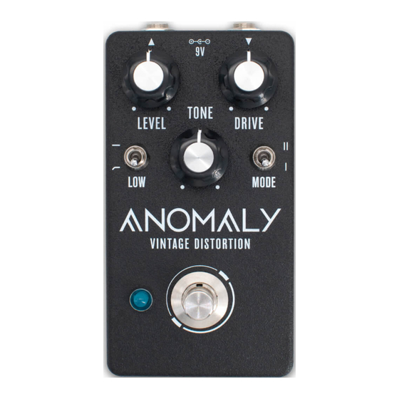
ANOMALY
BASED ON
Crowther Hot Cake (2008)
EFFECT TYPE
Distortion
PROJECT SUMMARY
An adaptation of a one of the original boutique overdrive/distortion pedals from the 1970s, notable for
its method of overdriving an op-amp directly rather than using diodes for clipping.
This documentation is for the kit version of the project. If you purchased the PCB by itself, please use the
PCB-only version
of the documentation instead. The circuit is the same, but the instructions are completely
different due to the specialized parts and assembly methods used in the kit.
ANOMALY VINTAGE DISTORTION
BUILD DIFFICULTY
Easy
DOCUMENT VERSION
1.0.0 (2024-01-26)
IMPORTANT NOTE
1
Advertisement
Table of Contents

Related Manuals for aion ANOMALY


Summary of Contents for aion ANOMALY
- Page 1 This documentation is for the kit version of the project. If you purchased the PCB by itself, please use the PCB-only version of the documentation instead. The circuit is the same, but the instructions are completely different due to the specialized parts and assembly methods used in the kit. ANOMALY VINTAGE DISTORTION...
-
Page 2: Table Of Contents
21 Enclosure Layout: Main & Footswitch PCBs 22 Enclosure Layout: Input/Output PCB 23 Final Testing & Assembly 24 Usage 25 Schematic 26 Full Parts List 27 Troubleshooting Information 28 Support & Resale Terms 29 Legal Information & Document Revisions ANOMALY VINTAGE DISTORTION... -
Page 3: Introduction
INTRODUCTION If this is your first pedal, welcome to the hobby and thank you for choosing Aion FX. You’ve just joined a community of over 40,000 people around the world with a passion for building homemade noise machines using obsolete electronics technologies, and we’re glad to have you! If you’ve done this before, it’s great to see you again and we’re confident you’ll find this build experience... -
Page 4: Packing List
22n (0.022) 47n (0.047) 82n (0.082) 100n (0.1) 100k 220k Electrolytic Capacitors NAME 10uF 47uF NAME 100uF TL071 MLCC Capacitors 8-pin socket NAME Transistors 100n (marked “104”) NAME Diodes 2N3906 NAME 1N5817 BZX85C10 (10V zener) BZX79C2V7 (2.7V zener) ANOMALY VINTAGE DISTORTION... - Page 5 9V battery snap 3-pin wire assembly header DC jack 4-pin wire assembly header Input/output jack Mounting nut, jack, 0.54" Outer washer, jack, 0.6" Lock washer, jack, 0.5" (thin) Enclosure Enclosure screws PCB, main circuit PCB, footswitch PCB, input/output/DC ANOMALY VINTAGE DISTORTION...
-
Page 6: Tools Needed
The tip should used to tighten the dress nut to avoid lot of pedals! be no more than 0.1” (2.5mm) wide. scratching or denting it (which can happen with metal tools). ANOMALY VINTAGE DISTORTION... -
Page 7: Component Identification
Charge pumps and delay chips Some voltage regulators The number of switch also look like this. They may also look like this. positions may vary. have more than 8 legs. WIRE ASSEMBLY WIRE ASSEMBLY HEADER DC JACK LED BEZEL ANOMALY VINTAGE DISTORTION... -
Page 8: Hardware Identification
MOUNTING NUT DRESS NUT LOCK WASHER DIAMETER: 0.36” / 9.1mm DIAMETER: 0.375” / 9.5mm DIAMETER: 0.4” / 10.1mm FOOTSWITCH MOUNTING NUT DRESS NUT LOCK WASHER DIAMETER: 0.6” / 15.2mm DIAMETER: 0.77” / 19.6mm DIAMETER: 0.6” / 15.2mm ANOMALY VINTAGE DISTORTION... -
Page 9: Pcb Assembly Overview
6. Transistors 7. Electrolytic capacitors Not all of these component types are included in each kit, so skip them if they aren’t applicable. Some types of film capacitors are taller than electrolytics, so those can be done last. ANOMALY VINTAGE DISTORTION... -
Page 10: Resistors
10 resistors at a time or the bottom of the board will get too crowded. If this is your first time soldering, watch tutorial videos on YouTube and make sure you get it down before you begin. You don’t want to practice or experiment on this board! ANOMALY VINTAGE DISTORTION... -
Page 11: Diodes
Z1 and Z2 have long part names that can be hard to read on the side of the body. It’s easier to identify them by size, since Z1 (the 10V zener) is significantly larger than Z2 (the 2.7V zener). ANOMALY VINTAGE DISTORTION... -
Page 12: Socket & Ic
ICs may have two different orientation marks: either a dot in the upper-left or a half-circle notch in the middle of the top side. Some ICs have both marks. This shows which way the IC should be rotated when inserting it into a socket (the socket also has a half-circle notch). ANOMALY VINTAGE DISTORTION... -
Page 13: Transistor
Once installed, bend the two outer legs to hold it in place on the board. Then, solder them and clip the leads. Be very careful of the orientation since the four parts face in three different directions. ANOMALY VINTAGE DISTORTION... -
Page 14: Capacitors (Non-Polarized)
C12 (100n MLCC) is always yellow. The value is hard to read on the side, but it can be identified by color. C3, C4 and C5 are not used in this variant of the circuit and should be left empty on the PCB. ANOMALY VINTAGE DISTORTION... -
Page 15: Wire Headers & Trimmer
They do fit pretty tightly in the holes, though, so press firmly. There’s also a 4-pin header on the I/O board that we will do in a later step. ANOMALY VINTAGE DISTORTION... -
Page 16: Capacitors (Polarized)
The longer leg is positive and fits in the square pad. These are the last of the on-board components. Now is the time to go back to page 12 and insert the IC into the socket. ANOMALY VINTAGE DISTORTION... -
Page 17: Footswitch Pcb
BLUE MARKING Once all three wire assemblies are soldered, set the footswitch PCB aside. We’ll solder the actual footswitch and LED in a later step. ANOMALY VINTAGE DISTORTION... -
Page 18: Input/Output Pcb
Red is positive (+), black is negative (-). After soldering, pull it tight. For even more strain relief, you can thread the snap through the loop to form a knot. (not shown) ANOMALY VINTAGE DISTORTION... -
Page 19: Enclosure Layout: Panel Mounts
You’ll need to hold the bezel in place when OUTER WASHER tightening the nut. The top of the bezel is fairly MOUNTING NUT sharp, so try using a rubber band for grip instead of pressing your finger against the bottom. ANOMALY VINTAGE DISTORTION... -
Page 20: Enclosure Layout: Panel Mounts (Cont.)
MOUNTING NUT LOCK WASHER BEZEL MOUNTING NUT & LED The dress nut acts as a mounting nut, unlike the footswitch dress nut. Use flat- nose pliers on the flat sides of the nut to tighten securely. FOOTSWITCH 125B ANOMALY VINTAGE DISTORTION... -
Page 21: Enclosure Layout: Main & Footswitch Pcbs
However, Aion FX projects are designed to be extremely easy to remove from the enclosure for troubleshooting, with no desoldering required—so with these kits, it’s actually much easier to “box it before you rock it”. -
Page 22: Enclosure Layout: Input/Output Pcb
Note the use of two mounting nuts on each of the jacks, one inside and one outside. The inner nut acts as a spacer to set the DC jack flush with the outside of the enclosure. The inner nuts should be threaded as far down as they can go. MOUNTING NUT OUTER WASHER LOCK WASHER MOUNTING NUT 125B ANOMALY VINTAGE DISTORTION... -
Page 23: Final Testing & Assembly
Last, just close the panel on the back using the four screws. Before that, though, grab a permanent marker and write your name and the completion date on the inside of the back panel. This is an accomplishment! ANOMALY VINTAGE DISTORTION... -
Page 24: Usage
• Mode (toggle) selects between standard (I) and Bluesberry (II) mode. Note on the switches The Anomaly replicates the original 2008 version of the Hot Cake, moving the internal slide switches for Bluesberry and XLF mode to the outside. The XLF mode is intended for bass, baritone or downtuned guitars. It works by increasing the size of the output capacitor. -
Page 25: Schematic
SCHEMATIC 220R 1N5817 2V7 0.5W MODE 100uF 100n 220k 47uF 2N3906 TL071P 10uF OMIT 100k OMIT OMIT ANOMALY VINTAGE DISTORTION... -
Page 26: Full Parts List
1N5817 2N3906 10uF electro 47uF electro BZX85C10 22n film 100uF electro BZX79C2V7 82n film 100n MLCC 47n film Potentiometers Switches PART VALUE PART VALUE PART TL071CP Level 50kA SPDT on-on (2) Drive 50kC 3PDT stomp Presence 50kB ANOMALY VINTAGE DISTORTION... -
Page 27: Troubleshooting Information
0.5V higher or lower than these listed voltages, it’s a good indicator of an issue and the voltages can help you or someone else narrow it down. VOLTAGES COMING SOON ANOMALY VINTAGE DISTORTION... -
Page 28: Where To Get Help
“goop” the PCB or otherwise obscure the source. In other words: you don’t have to go out of your way to advertise the fact that you use Aion FX kits, but please don’t go out of your way to hide it. -
Page 29: Legal Information
These kits are intended to be built by the customer. Aion FX is not responsible for language that may be used by the customer in the marketing or resale of the finished product.
Need help?
Do you have a question about the ANOMALY and is the answer not in the manual?
Questions and answers