Table of Contents
Advertisement
Quick Links
PROJECT NAME
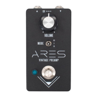
ARES
BASED ON
Echoplex EP-3 Preamp
EFFECT TYPE
Preamp & tone enhancer
PROJECT SUMMARY
A pedal adaptation of the preamp section of the EP-3 Echoplex tape echo unit. It captures the sound of
the EP-3 in bypass mode, favored by many guitarists for it "sweetening" effect on the tone.
This documentation is for the kit version of the project. If you purchased the PCB by itself, please
use the
PCB-only version
are completely different due to the specialized parts and assembly methods used in the kit.
ARES VINTAGE PREAMP
IMPORTANT NOTE
of the documentation instead. The circuit is the same, but the instructions
BUILD DIFFICULTY
Easy
DOCUMENT VERSION
1.0.1 (2024-08-08)
1
Advertisement
Table of Contents

Related Manuals for aion ARES VINTAGE PREAMP


Summary of Contents for aion ARES VINTAGE PREAMP
- Page 1 This documentation is for the kit version of the project. If you purchased the PCB by itself, please use the PCB-only version of the documentation instead. The circuit is the same, but the instructions are completely different due to the specialized parts and assembly methods used in the kit. ARES VINTAGE PREAMP...
-
Page 2: Table Of Contents
21 Enclosure Layout: Main & Footswitch PCBs 22 Enclosure Layout: Input/Output PCB 23 Final Testing & Assembly 24 Usage 25 Schematic 26 Full Parts List 27 Troubleshooting Information 28 Support & Resale Terms 29 Legal Information & Document Revisions ARES VINTAGE PREAMP... -
Page 3: Introduction
INTRODUCTION If this is your first pedal, welcome to the hobby and thank you for choosing Aion FX. You’ve just joined a community of over 100,000 people around the world with a passion for building homemade noise machines using obsolete electronics technology, and we’re glad to have you! If you’ve done this before, it’s great to see you again and we’re confident you’ll find this build experience... - Page 4 470n (0.47) Electrolytic Capacitors 100k NAME 220k 10uF 470k 47uF 100uF MLCC Capacitors NAME NAME 220pF (marked “221”) LT1054CP 100n (marked “104”) 8-pin socket 470n (marked “474”) Transistors Diodes NAME NAME 2N5484 1N5817 2N5485 1N4742A PCB adapter pins ARES VINTAGE PREAMP...
- Page 5 4-strand wire assembly, 108mm Input/output jack 3-pin wire assembly header Mounting nut, jack, 0.54" 4-pin wire assembly header Outer washer, jack, 0.6" Lock washer, jack, 0.5" (thin) Enclosure Enclosure screws PCB, main circuit PCB, footswitch PCB, input/output/DC ARES VINTAGE PREAMP...
-
Page 6: Tools Needed
The tip should used to tighten the dress nut to avoid lot of pedals! be no more than 0.1” (2.5mm) wide. scratching or denting it (which can happen with metal tools). ARES VINTAGE PREAMP... -
Page 7: Component Identification
Some voltage regulators The pins will be soldered to the also look like this. They may also look like this. adapter during kit assembly. have more than 8 legs. WIRE ASSEMBLY WIRE ASSEMBLY HEADER DC JACK LED BEZEL ARES VINTAGE PREAMP... -
Page 8: Hardware Identification
MOUNTING NUT DRESS NUT LOCK WASHER DIAMETER: 0.36” / 9.1mm DIAMETER: 0.375” / 9.5mm DIAMETER: 0.4” / 10.1mm FOOTSWITCH MOUNTING NUT DRESS NUT LOCK WASHER DIAMETER: 0.6” / 15.2mm DIAMETER: 0.77” / 19.6mm DIAMETER: 0.6” / 15.2mm ARES VINTAGE PREAMP... -
Page 9: Pcb Assembly Overview
6. Transistors 7. Electrolytic capacitors Not all of these component types are included in each kit, so skip them if they aren’t applicable. Some types of film capacitors are taller than electrolytics, so those can be done last. ARES VINTAGE PREAMP... -
Page 10: Resistors
10 resistors at a time or the bottom of the board will get too crowded. If this is your first time soldering, watch tutorial videos on YouTube and make sure you get it down before you begin. You don’t want to practice or experiment on this board! ARES VINTAGE PREAMP... -
Page 11: Diodes
1N5817 1N4742A 1N5817 1N5817 Next, you’ll populate the diodes. Diodes are polarized, so make sure to identify the polarity band (which indicates the “cathode”, or negative side) and match the band to the footprint on the PCB. ARES VINTAGE PREAMP... -
Page 12: Socket & Ic
ICs may have two different orientation marks: either a dot in the upper-left or a half-circle notch in the middle of the top side. Some ICs have both marks. This shows which way the IC should be rotated when inserting it into a socket (the socket also has a half-circle notch). ARES VINTAGE PREAMP... -
Page 13: Transistors
“5485” (used for Q2). Be very careful to line up the D-S-G labels with the markings on the PCB or the effect will not work. The component side of the PCB adapter should face upwards toward the potentiometer. ARES VINTAGE PREAMP... -
Page 14: Capacitors (Non-Polarized)
Note: C1, C6, C10 and C13 are blue MLCCs and taped to cardboard. The value will be written on the cardboard in order to distinguish them from each other. C14 and C15 (100n MLCCs) are always yellow and can be identified by color since the value printed on the side can be hard to read. ARES VINTAGE PREAMP... -
Page 15: Wire Headers & Trimmer
They do fit pretty tightly in the holes, though, so press firmly. There’s also a 4-pin header on the I/O board that we will do in a later step. ARES VINTAGE PREAMP... -
Page 16: Capacitors (Polarized)
The longer leg is positive and fits in the square pad. These are the last of the on-board components. Now is the time to go back to page 12 and insert the IC into the socket. ARES VINTAGE PREAMP... -
Page 17: Footswitch Pcb
BLUE MARKING Once all three wire assemblies are soldered, set the footswitch PCB aside. We’ll solder the actual footswitch and LED in a later step. ARES VINTAGE PREAMP... -
Page 18: Input/Output Pcb
Red is positive (+), black is negative (-). After soldering, pull it tight. For even more strain relief, you can thread the snap through the loop to form a knot. (not shown) ARES VINTAGE PREAMP... -
Page 19: Enclosure Layout: Panel Mounts
You’ll need to hold the bezel in place when OUTER WASHER tightening the nut. The top of the bezel is fairly MOUNTING NUT sharp, so try using a rubber band for grip instead of pressing your finger against the bottom. ARES VINTAGE PREAMP... -
Page 20: Enclosure Layout: Panel Mounts (Cont.)
MOUNTING NUT LOCK WASHER BEZEL MOUNTING NUT & LED The dress nut acts as a mounting nut, unlike the footswitch dress nut. Use flat- nose pliers on the flat sides of the nut to tighten securely. FOOTSWITCH 125B ARES VINTAGE PREAMP... -
Page 21: Enclosure Layout: Main & Footswitch Pcbs
However, Aion FX projects are designed to be extremely easy to remove from the enclosure for troubleshooting, with no desoldering required—so with these kits, it’s actually much easier to “box it before you rock it”. -
Page 22: Enclosure Layout: Input/Output Pcb
Note the use of two mounting nuts on each of the jacks, one inside and one outside. The inner nut acts as a spacer to set the DC jack flush with the outside of the enclosure. The inner nuts should be threaded as far down as they can go. MOUNTING NUT OUTER WASHER LOCK WASHER MOUNTING NUT 125B ARES VINTAGE PREAMP... -
Page 23: Final Testing & Assembly
Be careful not to over-tighten or you may damage the set screw. But if it’s not tight enough, the knob will be more likely to fall off or lose its alignment with the markings on the enclosure. Last, just close the panel on the back using the four screws. That’s it! ARES VINTAGE PREAMP... -
Page 24: Usage
So, if you notice it doesn’t seem to have much volume on tap, be aware that this is by design and not an issue with your build. The EP-3 circuit best used as an always-on tone sweetener or buffer than something you turn on to push the amp for lead parts. ARES VINTAGE PREAMP... -
Page 25: Schematic
SCHEMATIC 1N5817 1N5817 1N5817 100uF 10uF 100n 470n 470n 100n LT1054CP 10uF 2N5485 100k 220k 2N5484 100k 220pF 220pF 47uF ARES VINTAGE PREAMP... -
Page 26: Full Parts List
100n 470n film (0.1) MLCC 220pF 100n MLCC MLCC 100n film (0.022) MLCC 470n film (0.47) Transistors Potentiometer Switches PART VALUE PART VALUE PART VALUE PART LT1054CP 2N5484 Volume 500kB SPDT on-off-on 2N5485 3PDT stomp ARES VINTAGE PREAMP... -
Page 27: Troubleshooting Information
Note that IC pins are labeled counter-clockwise from the upper-left, as shown in the diagram to the right. For the JFETs, the pins are labeled on the PCB. VOLTAGE VOLTAGE VOLTAGE ARES VINTAGE PREAMP... - Page 28 “goop” the PCB or otherwise obscure the source. In other words: you don’t have to go out of your way to advertise the fact that you use Aion FX kits, but please don’t go out of your way to hide it.
- Page 29 These kits are intended to be built by the customer. Aion FX is not responsible for language that may be used by the customer in the marketing or resale of the finished product.
Need help?
Do you have a question about the ARES VINTAGE PREAMP and is the answer not in the manual?
Questions and answers