Table of Contents
Advertisement
Quick Links
WARNING: If the information in these instructions is not followed exactly, weakening or failure of the erected
structure may result causing property damage, personal injury, or loss of life.
All brackets designed and sold by RioOutdoors.com are to be used for building pergolas only and are not to be used for
other structure construction purposes.
•
Thoughtfully engineered Brackets eliminate all wood-joinery skills requirements.
•
Skills required: leveling ground, drilling pilot holes, and driving lag screws into lumber.
•
Easy lift and place U-channels eliminate need for lifting equipment. Super-easy assembly work.
•
Self-aligning design squares up structure automatically.
•
Estimated Assembly Time is less than 2-1/2 hours (not including deck).
1 |
P a g e
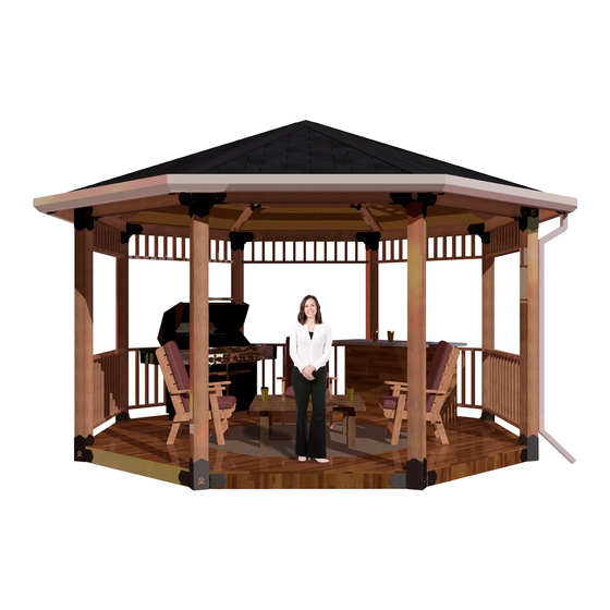
Installation Instructions
6x6 Floating Octagon Pergola Kit
Pergola Kits
Figure 1: Items included in the kit, (
Items not included in this kit: wood, tools, some hardware.
6F-O
).
������������ #
������������������������ ���� ����
Advertisement
Table of Contents

Related Manuals for RioOutdoors 6F-O


Summary of Contents for RioOutdoors 6F-O
- Page 1 WARNING: If the information in these instructions is not followed exactly, weakening or failure of the erected structure may result causing property damage, personal injury, or loss of life. All brackets designed and sold by RioOutdoors.com are to be used for building pergolas only and are not to be used for other structure construction purposes.
-
Page 2: Table Of Contents
CTAGON PERGOLA ASSEMBLY WORK OUTLINE 1.1 S ......3 AFETY AND WARNING INFORMATION 1.2 T ........... 4 OOLS REQUIRED 1.3 C # 6F-O ........5 1.10 A ONTENTS OF SSEMBLING FLOOR CORNER WAY OCTAGON ELBOW ............. 15 1.4 L BRACKETS... -
Page 3: Safety And Warning Information
GENERAL INFORMATION 1.1 SAFETY AND WARNING INFORMATION 1.1.1 Building Permit & Inspection Requirements We recommend that you consult with your local building permit office and obtain advice and any required building permits and inspection approvals from the local building inspection department or the having authority over building codes. 1.1.2 Other Cautions CAUTION: Adhere to all safety requirements. -
Page 4: Tools Required
1.2 TOOLS REQUIRED Listed below, are common tools required for pergola projects. These tools are not included in this kit. Your pergola project may not require all tools. Select and acquire the tools for your project from the “Required for” column in this table. Description Tool Purpose Required for... -
Page 5: Contents Of Kit
The contents of this kit are shown in the table, below. Before you begin your project, take an inventory of all items that you received from us. If any items are missing, contact us directly via email at info@RioOutdoors.com. Include your name and shipping address and your order number, if available. -
Page 6: General Lumber Requirements Information
1.5 GENERAL LUMBER REQUIREMENTS INFORMATION We have designed the corner elbow brackets to provide automatic alignment of the header 6x6s. By making certain all header 6x6s are of the same length and not warped, following the instructions properly, and securing the 6x6s to the elbow brackets as instructed, you will achieve a perfect hexagonal shape for your pergola. -
Page 7: Floating System
To create a deck, you must add support beams every 24”, or less, to support the deck boards. You may toenail the support beams in place or choose an easier and more precise mounting method using our Beam Support Brackets (SKU# 24BS, available at RioOutdoors.com). P a g e... - Page 8 1.6.2 Floor Leveling and Preparation. Plan to assemble a floating pergola where you can excavate and create a level platform, at least, the overall outer dimensions of the pergola. If soil type is sandy, soft, or wet, you must consider adding concrete blocks or pier blocks under the posts of the pergola to prevent the pergola from sinking into soil.
-
Page 9: Overall Pergola Size
1.7 OVERALL PERGOLA SIZE We have designed the corner elbow brackets to provide automatic alignment of the floor floating 6x6s and the header 6x6s. By making certain all outer perimeter 6x6s are of the same length, following the instructions properly, and securing the 6x6s to the elbow brackets as instructed, you will achieve a perfect Octagonal floating deck base for your pergola. -
Page 10: Side Elevation Diagram
1.8 SIDE ELEVATION DIAGRAM Based on the height of the post used, the diagram below provides the side elevation profile for this pergola system. POST HEIGHT DIM A (in.) (in.) 90 1/2 102 1/2 114 1/2 126 1/2 138 1/2 The Post Height, above, equals the outer height of the pergola. - Page 11 1.9 OCTAGON PERGOLA ASSEMBLY WORK OUTLINE 1.9.1 Brackets Application Depiction 11 | P a g e...
- Page 12 1.9.2 Posts Preparation Measure and prepare eight posts of equal lengths. Use a power miter saw to cut the posts to equal lengths. 1.9.3 Headers Preparation Prepare sixteen (16) 4x4 lumber members (8 for headers and 8 for floating floor footers) of equal length by following the steps, below.
- Page 13 1.9.4 Octagon floor frame construction 1. Lay out the eight floor 6x6 footer members in a rough octagon shape. 2. Start in one corner and add a 2-Way Octagon Elbow on top of the two adjacent 6x6s. 3. Secure the two adjacent 6x6s to the elbow. See Section 1.11. 4.
- Page 14 9. Slide a 2-way octagon elbow on top of each post. 10. Secure the 2-way octagon elbows to the post tops. See section 1.12. 11. Repeat steps 8 and 9 for all post tops. 12. Lift and place a header member in the open U-channels between two posts. Repeat adding all headers. 13.
-
Page 15: Brackets
1.10 ASSEMBLING FLOOR CORNER 2-WAY OCTAGON ELBOW BRACKETS Before starting assembly work, measure the length of each perimeter 6x6 to verify that they are of equal length and make certain each member is straight (has no bow nor is warped). On the ground, mark the location of one corner post. Start assembly at this post location and continue assembling floor members and corner elbow brackets around the perimeter. - Page 16 5. Wrap a piece of electrical tape around the drill bit, spaced 1-1/4” from the drill bit tip. This will act as a hole depth indicator when you drill each pilot hole. Pilot holes should be drilled at least 1-1/4” deep. A little bit deeper is acceptable but do not drill less than the required 1-1/4”...
- Page 17 8. Use a ratchet driver and a 7/16” socket to drive one ¼” X 1-1/4” Lag screw through the pilot holes you drilled. Total of four lag screws are required. One in each lower hole on the sides of the U-channels. 9.
-
Page 18: Posts Installation
1.11 POSTS INSTALLATION 1. Slide a 6x6 post inside the open vertical tube in all corners’ 2-way octagon elbow brackets. If post resists sliding easily, tap top of post lightly with a hammer. Post must slide all the way down to the bottom of the square tube. 2. - Page 19 3. Drive one 1/4x1-1/4” lag screw through each pilot hole you drilled and tighten down using a ratchet and 7/16” socket. 4. Repeat steps 2 to 3 at all corners. Check top of floor 6x6s for level one more time and adjust as necessary to maintain level. 19 | P a g e...
-
Page 20: Post-Top Brackets Installation
1.12 POST-TOP BRACKETS INSTALLATION 1. Slide a 2-way octagon elbow bracket’s tube over the 6x6 post top after aligning the header receiver u-channels in the proper directions. Let gravity work and pull the bracket all the way down on top of the post. If you feel resistance tap lightly on top of the elbow bracket until it slides all the way down. - Page 21 3. Identify the four 5/16” holes which are on the sides of the gussets in the elbow bracket. 4. Drill 3/32” X 1-1/4” deep pilot holes at the center of four 5/16” Holes. Locate pilot holes at the center of each 5/16” hole.
-
Page 22: Headers Installation
1.13 HEADERS INSTALLATION 1. Lift and place one header into the U-channels of adjacent post top brackets. 2. The resting positions of headers in the U-channels are shown, below. 22 | P a g e... - Page 23 3. Locate the two 5/16” holes on each vertical face of the U-channels holding the 4x4 header. Drill 3/32” X 1-1/4” deep pilot holes at the center of four 5/16” Holes. Locate pilot holes at the center of each 5/16” hole. Repeat for the opposite end of the header.
-
Page 24: Nstalling Deck Board Support Beams
1.14 INSTALLING DECK BOARD SUPPORT BEAMS 1. Decide on which direction you would like the deck boards to run. Deck support beams run in a perpendicular direction to the deck boards. Support beams should be spaced, approximately, every 24” or less to support the deck boards. The deck support structure required depends on the overall size of the pergola. -
Page 25: Nstalling Deck Boards
1.15 INSTALLING DECK BOARDS 1. Plan and lay down your deck boards starting in the center of the pergola. Work outward from the center in both directions. Use the thick end of a wood shim as a spacer to leave an 1/8”-1/4” gap between each board row to allow for expansion. 2. - Page 26 Was it easy to do? Did parts fit easily and properly? Do you like the quality of our products and design styles? Is your pergola structure sturdy and strong? Please go to RioOutdoors.com and provide us with your review.
-
Page 27: Warranty Policy Statement
Warranty protects against defect in manufacture only, unless herein specified otherwise. Any part(s) found to be defective during the warranty period as outlined above will be repaired or replaced at RioOutdoors.com’s option provided that the defective part is returned, if requested by RioOutdoors.com. Alternatively, RioOutdoors.com may at its own discretion fully discharge all its obligations under the warranty by refunding the verified purchase price of the product to the original purchaser. -
Page 28: Imitations Of Liability
Parts where the RioOutdoors.com logo has been altered, deleted, removed, or made illegible will void this warranty. Minor movement, expansion and contraction of the steel parts is normal and is not covered under the terms of this warranty.
Need help?
Do you have a question about the 6F-O and is the answer not in the manual?
Questions and answers