Hoover ELITE REWIND U5507-900 Service Manual
Upright cleaner
Hide thumbs
Also See for ELITE REWIND U5507-900:
- Owner's manual (24 pages) ,
- Owner's manual (24 pages) ,
- User manual (416 pages)
Table of Contents
Advertisement
Quick Links
Advertisement
Table of Contents

Related Manuals for Hoover ELITE REWIND U5507-900


Summary of Contents for Hoover ELITE REWIND U5507-900
- Page 1 This Owner's Manual is provided and hosted by Appliance Factory Parts. HOOVER U5511900 Owner's Manual Shop genuine replacement parts for HOOVER U5511900 Find Your HOOVER Vacuum Cleaner Parts - Select From 1455 Models -------- Manual continues below --------...
- Page 2 Model U5507/09-900/950 U5511/12-900 English Language Page Color(cover/body) Material Size(W*H) 210x300 100g Date Designer 2008.04.18 Yang zhihua Part No. Description service manual MFL34895107 Chage Record Change content Date Designer Confirm ECO No.
- Page 3 Upright Cleaner ® Aspirateur vertical Elite Rewind SERVICE MANUAL MODEL: U5507/09-900/950 U5511/12-900 CAUTION BEFORE SERVICING THE UNIT, READ THE SAFETY PRECAUTIONS IN THIS MANUAL. APR.2008 P /NO.: MFL34895107 Printed in China...
-
Page 4: Table Of Contents
CONTENTS IMPORTANT SAFEGUARDS ................3 CLEANER DESCRIPTION ................... 4 SPECIFICATIONS ....................4 PARTS ........................4 REPLACEMENT INSTRUCTIONS ..............5 TROUBLESHOOTING ..................9 SCHEMATIC DIAGRAM ..................10 EXPLODED VIEW ....................11... -
Page 5: Important Safeguards
IMPORTANT SAFEGUARDS WARNING Your safety is important to us. To reduce the risk of fire, electrical shock, injury to persons, or damage when using your vacuum cleaner, follow basic safety precautions, including the following: 1. Disconnect power supply before servicing and/or cleaning the unit. 2. -
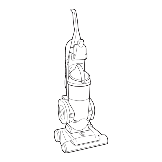
Page 6: Cleaner Description
CLEANER DESCRIPTION After assembly, the cleaner will look like the picture below. SPECIFICATIONS Model U5507/09-900/950 U5511/12-900 Power supply On the rating label Ampacity On the rating label Dimension/upright position (WxDxH) 823x385x290 Cord length Weight 7.8 KG 7.8 KG PARTS Model U5507/09-900/950 U5511/12-900 Tank dust... -
Page 7: Replacement Instructions
REPLACEMENT INSTRUCTIONS WARNING Electrical Shock or Personal Injury Hazard Disconnect electrical supply before servicing or cleaning the unit. Failure to do so could result in electrical shock or personal injury from cleaner suddenly starting. Dirt cup How to empty When to empty Disconnect cleaner from electrical It is recommended that the dirt cup be outlet. - Page 8 WARNING Electrical Shock or Personal Injury Hazard Disconnect electrical supply before servicing or cleaning the unit. Failure to do so could result in electrical shock or personal injury from cleaner suddenly starting. Dirt and debris can then be cleaned from the filter cartridge by br ushing with the cleaner’s combination tool.
- Page 9 WARNING Electrical Shock or Personal Injury Hazard Disconnect electrical supply before servicing or cleaning the unit. Failure to do so could result in electrical shock or personal injury if the cleaner starts suddenly. 5-14 5-15 5-16 5-17 5-18 5-19...
- Page 10 WARNING Electrical Shock or Personal Injury Hazard Disconnect electrical supply before servicing or cleaning the unit. Failure to do so could result in electrical shock or personal injury if the cleaner starts suddenly. 5-21 5-22 5-20 5-23 5-26 5-20 and 5-21 5-25 5-24 5-21...
-
Page 11: Troubleshooting
TROUBLESHOOTING 5-14 5-19... -
Page 12: Schematic Diagram
SCHEMATIC DIAGRAM Neutral Live Switch Thermal Protector Motor • : CONNECTED BY/WITH – TERMINAL AND RECEPTACLE – CONNECTOR – NYLON CONNECTOR – THERMAL PROTECTOR... -
Page 13: Exploded View
EXPLODED VIEW BASE ASSEMBLY.BODY MEGBP1 MCKBG1 MAMBB1 MCKBR1 MBGBR1 MHYBC1 MCKBC1 AHDBR1 EBFBA1 ADQBE1 MEABE1 EADBJ1 MCKBE8 MCQBM1 EAUBA1 AJJBM1 MCQBA1... - Page 14 EXPLODED VIEW COVER ASSEMBLY, BODY&HANDLE ASSEMBLY ABDCA1 AEJCL1 MCKCB1 MCKCL1 MEBHL1 AGBNU1 ADVHB1 MEBHU1...
- Page 15 EXPLODED VIEW TANK ASSEMBLY, DUST MFGTA1 MHYTA1 MCKTS1 ADQTC1 MGJTC1 AESTA1 MDQTF1 MJMTD1 MBGTR1 MGJTB1...
- Page 16 EXPLODED VIEW PLATE ASSEMBLY, BOTTOM&COVER ASSEMBLY, HEAD MJDSH9 MJDSH8 MFCCA1 ACQCH1 MKBCA1 MKCCV1 MEGCP8 MEGCP9 MDSCH1 MEJCH1 MGECG1 MEYCC1 MHACH1 MEYCA1 AHRSA1 MASAA1 MCKAT1 MGJPB1...
- Page 17 EXPLODED VIEW HOSE ASSEMBLY& ACCESSORIES AEMAF1 AGBN51 MEGAA1 MFVAC1...
Need help?
Do you have a question about the ELITE REWIND U5507-900 and is the answer not in the manual?
Questions and answers