
Subscribe to Our Youtube Channel
Related Manuals for Soundoff Signal A500 Series


Summary of Contents for Soundoff Signal A500 Series
- Page 1 INSTALLATION INSTRUCTIONS A500 SERIES SIREN SCAN FOR NEWEST VERSION A500 Series Siren 0000JL 0823 REV C...
- Page 2 The siren system is intended for use by authorized personnel only. It is the user’s responsibility to ensure they understand and operate the emergency warning devices in compliance with all applicable city, state, and federal laws and regulations. SoundOff Signal assumes no liability for any loss resulting from the use. WARNING •...
-
Page 3: Table Of Contents
A500 SERIES SIREN Table of Contents Introduction ..............4 Technical Specifications . -
Page 4: Introduction
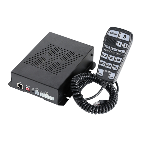
INTRODUCTION A500 100W/200W CONTENTS Thank you for choosing to equip your vehicle with SoundOff COMPONENT Signal’s A500 Series Siren. The A500 is a compact siren and lighting controller to meet the basic functions required for SIREN UNIT emergency vehicles. HANDHELD CONTROLLER... -
Page 5: Siren Functions / Controller Layout Information
A500 SERIES SIREN SIREN FUNCTIONS HAND HELD CONTROLLER SIREN BUTTON: 3 BUTTON: The 1st press and release will play WAIL tone, the A press and release will activate LVL Outputs 2nd press and release will play YELP tone, the 3rd press and release 3, 2 &... -
Page 6: Amplifier Layout Information
A500 SERIES SIREN SIREN LAYOUT INFORMATION *200W SIREN FRONT VIEW A. LEVEL 1,2,3 FUSE LOCATIONS: 10AMP C. MAIN SIREN AMP FUSE LOCATION: 100W - 15AMP (12V) / 7.5AMP (24V) B. MAIN SIREN POWER WIRE HARNESS (page *200W - 20AMP (12V) / 10AMP (24V) for more details) D. -
Page 7: Electrical Installation / Main Siren Harness / Speaker Siren Harness
A500 SERIES SIREN ELECTRICAL INSTALLATION / MAIN SIREN HARNESS SIREN HARNESS FUNCTION WIRE COLOR WIRE SIZE HORN RING IN WHITE/BLACK INPUT 18AWG HORN RING OUT WHITE OUTPUT 18AWG AUX 5 OUTPUT (0.2 Amps) BLACK OUTPUT 18AWG AUX 4 OUTPUT (0.2 Amps) - Page 8 A500 SERIES SIREN ELECTRICAL INSTALLATION / MAIN SIREN HARNESS CONTINUED 4. Press the RR button, with a small screwdriver, Auxiliary Input: (Violet Wire) adjust the radio rebroadcast volume potentiom- The input is an optional input which will remotely eter located on the back of the siren amplifier to...
-
Page 9: Wiring Diagrams
A500 SERIES SIREN WIRING DIAGRAM FRONT WIRE HARNESS 14 AWG BLACK GROUND 14 AWG RED 12V 24V POWER 14 AWG RED 12V 24V POWER 14 AWG RED 12V 24V POWER REAR WIRE HARNESSES Wire capacity requirements for siren amplifier 16 AWG BLUE LVL 1 OUTPUT 8 AMPS (incoming power)-each supply and ground wire. -
Page 10: Horn Ring Wiring Diagram / Horn Ring Function Table
A500 SERIES SIREN HORN RING WIRING DIAGRAM *Only necessary when the horn is a POSITIVE input and requires more than 0.2 Amps. HORN RING INFORMATION STANDBY Standby MODE MODE INPUT (IGN OFF (*IGN ON, PWR (*IGN ON, WAIL YELP TONE... -
Page 11: Programming Siren & Aux Button Functions / Dip Switch Settings
A500 SERIES SIREN PROGRAMMING NOTE: ENSURE SIREN IS IN STANDBY MODE FOR ALL PROGRAMMING STEPS, IGNITION ON, POWER ON CONTROL PANEL ACTIVE. ALL PROGRAMMING FUNCTIONS WILL BE LOCKED AFTER 20 MINUTES FROM IGNITION ON. TO PROGRAM AFTER IGNITION ON FOR 20 MINUTES, IGNITION MUST BE RESTARTED TO RESTORE PROGRAMMING ACCESS. - Page 12 A500 SERIES SIREN PROGRAMMING CONTINUED NOTE: ENSURE SIREN IS IN STANDBY MODE FOR ALL PROGRAMMING STEPS, IGNITION ON, POWER ON CONTROL PANEL ACTIVE. ALL PROGRAMMING FUNCTIONS WILL BE LOCKED AFTER 20 MINUTES FROM IGNITION ON. TO PROGRAM AFTER IGNITION ON FOR 20 MINUTES, IGNITION MUST BE RESTARTED TO RESTORE PROGRAMMING ACCESS.
- Page 13 A500 SERIES SIREN PROGRAMMING CONTINUED NOTE: ENSURE SIREN IS IN STANDBY MODE FOR ALL PROGRAMMING STEPS, IGNITION ON, POWER ON CONTROL PANEL ACTIVE. ALL PROGRAMMING FUNCTIONS WILL BE LOCKED AFTER 20 MINUTES FROM IGNITION ON. TO PROGRAM AFTER IGNITION ON FOR 20 MINUTES, IGNITION MUST BE RESTARTED TO RESTORE PROGRAMMING ACCESS.
-
Page 14: Siren Tone Defaults
A500 SERIES SIREN SIREN TONE DEFAULTS TONE DEFAULTS PROGRAMMABLE TONES CA TITLE 13 OFF *CA TITLE 13 ON RR MAN OVERRIDE Manual Wail, Immediate OFF when Released HORN BUTTON HORN4 HORN4 MAN BUTTON Manual Wail, Immediate OFF when Released Manual Wail, Immediate OFF when Released... -
Page 15: Siren Tone List / Hf Tone Scroll
A500 SERIES SIREN SIREN TONE LIST / HR (HANDS FREE) TONE SCROLL TONES Tone List for SIREN Override Tone List for MAN Override Tone List for Tone List for Tone List for BUTTON / Wail, Yelp, SIREN BUTTON / Wail,... -
Page 16: Warranty Information
Each RMA # is good for only one (1) return and will expire (30) days after the date it was issued. Products must be shipped back to SoundOff Signal and the RMA # clearly marked on the outside of the package near the shipping label. Please use the...
Need help?
Do you have a question about the A500 Series and is the answer not in the manual?
Questions and answers