Table of Contents
Advertisement
Quick Links
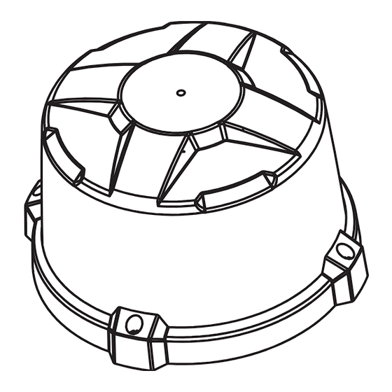
HIGH DOME BEACON
HIGH DOME
MAGNET MOUNT - ENRBCSHM(x)1(x)Z(xxx)
COMBO: FLAT/PIPE MOUNT - ENRBCSHC(x)1(x)Z(xxx)
LOW DOME
MAGNET MOUNT - ENRBCSLM(x)1(x)Z(xx)
COMBO: FLAT/PIPE MOUNT - ENRBCSLC(x)1(x)Z(xxx)
WARNING
•HIGH CURRENT interconnects must be properly terminated. Poor crimp quality can cause heat
build-up and fire. Follow crimp connector manufacturer instructions.
•DO NOT install this product or route any wires in the Air Bag Deployment Zone. Refer to vehicle
Owner's Manual for deployment zones.
•Do NOT use system to disconnect headlights, brake lights or other safety equipment.
•Unit may become hot to touch during normal operation.
•Failure to properly install connectors, fuses or wiring may cause vehicle failure or fire.
•Installation must only be performed by trained technician. Installer must determine vehicle wiring
configuration and proper integration of system.
•Use proper wire gauge. All power wires connecting to positive (+) or negative (-) battery terminal
or local chassis ground (-) must be sized to supply at least 125% of max. current and properly fused at
power source.
•Install protective grommets when routing wire through firewall or metal.
www.soundoffsignal.com/sales-support. If you have questions regarding this product, contact Technical Services, Monday - Friday, 8 a.m. to 5 p.m. or after hours 5 p.m. to 8 p.m. EST
at 1.800338.7337 (press #4 to skip the automated message). Questions or comments that do not require immediate attention may be emailed to techservices@soundoffsigal.com.
1.800.338.7337 / www.soundoffsignal.com
1.
Distributed by
Installers and users must comply with all applicable federal, state and local laws regarding use and installation of warning devices.
Improper use or installation may void warranty coverage. To review our Limited Warranty Statement & Return Policy for this or any SoundOff Signal product, visit our website at
S U P E R I O R C U S TO M E R R E L AT I O N S H I P S . S M A RT LY D E S I G N E D L I G H T I N G & E L E C T R O N I C S O L U T I O N S .
TECHNICAL SPECIFICATIONS
Dimensions:
Input Voltage:
Standby Current:
Reverse Polarity Protection:
Electrical Transient Protection:
Wiring:
CURRENT CONSUMPTION
MODULE
INPUT VOLTAGE
CONFIGURATION
3 LED Single Color
9-17.5Vdc
6 LED Single Color
9-17.5Vdc
9 LED Single Color
9-17.5Vdc
12 LED Single Color
9-17.5Vdc
12 LED Dual Color
9-17.5Vdc
18 LED Tri Color
!
This product contains high intensity LED devices. To
prevent eye damage, DO NOT stare into the light
Please see pages 2-3 for Mounting Instructions
NOTICE:
9-17.5Vdc
<0.0001 Amps after 10 seconds of no
active control inputs
Yes
ISO7637-2 for 12V systems
Approx. 18" length. Type TXL 4x 16AWG
Power/Ground, 6x 20AWG Control
CURRENT DRAW
WATTS FLASHING
RANGE
(MAXIMUM)
@ 12.8Vdc
0.5 Amps
3.2 Watts
1.0 Amps
6.4 Watts
1.5 Amps
9.6 Watts
2.0 Amps
12.8 Watts
1.0 Amps
6.4 Watts
9-17.5Vdc
1.0 Amps
6.4 Watts
WARNING
beam at close range.
nROADS Beacon 05.16
Advertisement
Table of Contents

Subscribe to Our Youtube Channel
Related Manuals for Soundoff Signal nROADS ENRBCSHM 1 Z Series


Summary of Contents for Soundoff Signal nROADS ENRBCSHM 1 Z Series
- Page 1 Installers and users must comply with all applicable federal, state and local laws regarding use and installation of warning devices. Improper use or installation may void warranty coverage. To review our Limited Warranty Statement & Return Policy for this or any SoundOff Signal product, visit our website at www.soundoffsignal.com/sales-support.
-
Page 2: Pipe Mount
nROADS Mounting Instructions Flat Mount: 1. Using the supplied gasket, mark the center hole and three mounting holes on the surface the beacon will be mounted to. 2. Drill your holes. a. The center hole should be large enough for the wires to pass, between 5/8"... -
Page 3: Power On/Off
nROADS Mounting Instructions Magnet Mount: 1. Locate surface where beacon will be mounted. 2. Place beacon with the "REAR" facing the rear of the vehicle. This is important for specific modes. Cig Plug Operation: 1. See Cig Plug diagram at left for POWER ON/OFF and PATTERN SELECT switch locations. - Page 4 ELECTRICAL INSTALLATION (applies to permanent mounting options only) Power Wires: 1. Route customer supplied power and ground cables which are properly sized for the current consumption of the beacon (rated for a minimum of 125% above maximum current draw) between the power source (battery) and the beacon power and ground cables.
- Page 5 ELECTRICAL INSTALLATION (CONTINUED) Product Configuration: 1. The four control wires (blue, orange, yellow and pink) can each be assigned a function from the flash pattern table, which include: a. Output a pattern, b. Enable a scene (where lights are steady on), c.
-
Page 6: Flash Patterns
*fpm=Flashes per Minute FLASH PATTERNS **fps=Flashes per Second nROADS to nROADS Name Sequence Sync2 Compatible Compliant Compatible RandomAction 1 Variable RandomAction 2 Variable RandomAction 3 (Blue wire/Cig Plug Variable LED Module Count Dependent default) RandomAction 4 (Orange wire default) Variable LED Module Count Dependent Rotate 250 Rotating... - Page 7 *fpm=Flashes per Minute FLASH PATTERNS CONTINUED **fps=Flashes per Second Name Sequence nROADS to nROADS Compatible Sync2 Compatible Compliant Double Alt L/R Double Double Alt²/Sim Power Pulse Alt L/R Power Pulse Power Pulse Alt²/Sim Road Runner Alt L/R Road Runner Road Runner Alt²/Sim Slow Runner Alt L/R...
- Page 8 FLASH PATTERNS CONTINUED Name Sequence nROADS to nROADS Compatible Sync2 Compatible Compliant Right Scene Scene Control Front Scene Scene Control Rear Scene Scene Control All Scene Scene Control Low Power 30% Low Power Mode Control (1 Wink) Low Power 50% (Pink wire default) Low Power Mode Control (2 Winks) Sync2 Compatibility Chart (nFORCE Secondary, nFORCE FIT, Dual Color Intersector)
- Page 9 REPLACEMENT PARTS & ACCESSORIES ITEM PART# DESCRIPTION PNRBCDRV2 DRIVER W/ CONNECTOR PNRBCDRV1 DRIVER W/O CONNECTOR PNRBCLUP6A UPWARD LIGHT ENGINE PNRBCLUP6B UPWARD LIGHT ENGINE PNRBCLUP6G UPWARD LIGHT ENGINE PNRBCLUP6R UPWARD LIGHT ENGINE PNRBCLUP6W UPWARD LIGHT ENGINE PNRBCDMHA AMBER HIGH DOME PNRBCDMHC CLEAR HIGH DOME PNRBCDRNGB BLACK DRESS RING...
- Page 10 nROADS TROUBLESHOOTING Normal Operation Under normal operation the Beacon will Flash when a combination of the four control inputs are connected to +Vdc. The Beacon is OFF and in a low power Standby Mode after 10 seconds of no active control inputs. No Operation No Power;...
-
Page 11: Warranty Exclusions
* RMA # will not be given without this information. ** If available, please provide this information. SoundOff Signal will NOT accept returns without an RMA #. Each RMA # is good for only one (1) return and will expire (30) days after the date it was issued.
Need help?
Do you have a question about the nROADS ENRBCSHM 1 Z Series and is the answer not in the manual?
Questions and answers