
Related Manuals for Canon imageRUNNER ADVANCE DX C477


Summary of Contents for Canon imageRUNNER ADVANCE DX C477
- Page 1 ADVANCE DX C477iF/C477iFZ SERVICE MANUAL Canon February 8, 2021 Rev. 3 COPYRIGHT © 2021 CANON INC. CANON imageRUNNER ADVANCE DX C477iF/C477iFZ Rev. 3 PRINTED IN U.S.A.
- Page 2 When changes occur in applicable products or in the contents of this manual, Canon will release technical information as the need arises. In the event of major changes in the contents of this manual over a long or short period, Canon will issue a new edition of this manual.
- Page 3 Important Notices Copyright The copyright of this document belongs to Canon Inc. This document may not be copied, reproduced or translated into another language, in whole or in part, without the prior consent of Canon Inc. Copyright CANON INC. 2020 Caution Use of this manual should be strictly supervised to avoid disclosure of confidential information.
- Page 4 Important Notices Symbols Explanation Symbols Explanation Cleaning is needed. Measurement is needed. The following rules apply throughout this Service Manual: 1. Each chapter contains sections explaining the purpose of specific functions and the relationship between electrical and mechanical systems with reference to the timing of operation. In the diagrams, represents the path of mechanical drive;...
-
Page 5: Table Of Contents
Contents Contents Safety Precautions....................1 Laser..............................2 Laser Safety............................2 How to Handle the Laser Scanner Unit ....................2 Power Supply / Lithium Battery......................2 Turn power switch ON........................... 2 Power Supply............................3 Notes When Handling a Lithium Battery....................3 Toner Safety............................4 About Toner............................4 Handling Adhered Toner........................4 Notes on works............................4... - Page 6 Contents Outline of Electric Circuits ........................44 ADF scan operation sequence (common to both 2-sided/1-sided)............44 Scanner Unit............................48 Pickup Feed System........................... 49 Controller System..........................55 Overview............................55 Startup Sequence..........................57 Shutdown Sequence........................... 58 Motion Sensor.............................58 Laser Exposure System........................60 Overview............................60 Specifications.............................
- Page 7 Contents 4. Periodical Service..................119 Periodically Replacement Parts...................... 120 Consumable parts........................... 121 5. Parts Replacement and Cleaning............... 122 Preface............................123 Outline..............................123 List of Parts............................. 124 External / Internal Cover........................124 Main Unit............................129 Electrical Components List.........................132 External Cover/Interior System....................... 146 Removing the Rear Cover........................146 Removing the Front Cover.........................
- Page 8 Contents Removing the ADF Feed Frame......................190 Removing the Copyboard Glass Unit....................207 Removing the Scanner Unit (Front).....................208 Removing the Reader Motor......................212 Removing the CIS Holder........................212 Controller System..........................214 Removing the Wi-Fi PCB........................214 Removing the Main Controller Sub Cover /Main Controller Cover............214 Removing the HDD...........................
- Page 9 Contents Removing the Finisher Lower Feed Unit..................... 278 Removing the Finisher Unit........................ 280 Removing the Finisher Lower Solenoid Unit..................285 Removing the Finisher Tray Unit......................287 6. Adjustment....................288 Pickup Feed System........................289 Image Position Adjustment ........................289 Original Feed System........................291 Skew Adjustment (at Stream Scanning of Originals)................
- Page 10 Contents Function Overview..........................340 Saving and Collecting Debug Logs..................... 343 Service Mode Relating to Debug Logs....................356 8. Error/Jam/Alarm................... 358 Overview............................359 Location Code...........................359 Pickup Position Code.........................360 Pickup size............................360 Points to Note When Clearing MN-CON .....................362 Points to Note When Clearing HDD....................362 Remedies to be performed when E602-xxxx or E614-xxxx error is displayed.........362 Error Code............................366 Error Code Details..........................366...
- Page 11 Contents Setting of Menu Switch (MENU)......................732 Setting of Numeric Parameter (NUMERIC Param.)................733 Setting of Destination (TYPE)......................735 Setting of Printer Functions (PRINTER)....................736 IPFAX Setting........................... 738 Initialization of Set Value (CLEAR)..................... 739 Test Mode (TEST)..........................739 Service Report (REPORT)......................... 743 10.
- Page 12 Contents Super G3 FAX Board-AT1.......................836 Points to Note at Installation.......................836 Checking the Contents........................836 Installation Outline Drawin......................... 836 Essential Items to Be Performed Before Installation................836 Installation Procedure........................837 Checking the Operation........................843 APPENDICES....................845 Service Tools...........................846 List of Special Tools.......................... 846 Solvents and Oils..........................
-
Page 13: Safety Precautions
Safety Precautions Laser............. 2 Power Supply / Lithium Battery..... 2 Toner Safety..........4 Notes on works........4... -
Page 14: Laser
Safety Precautions Laser Laser Safety Since radiation emitted inside this machine is completely confined with protective housings and external covers, the laser beam cannot escape from the machine during any phase of normal use by users. Therefore, this machine is classified as a Class 1 laser product under the international standard IEC60825-1 that is regarded as safe during normal use. -
Page 15: Power Supply
Safety Precautions CAUTION: Do not turn off the main power switch while the progress bar is indicated, during which access is made to the HDD. If deprived of power, the HDD can suffer a fault (E602). Power Supply • As a general rule, do not use extension cords. If an extension cord must be used, however, use one for local rated voltage and over, untie the cord binding, and insert the power plug completely into the extension cord outlet to ensure a firm connection between the power cord and the extension cord. -
Page 16: Toner Safety
Safety Precautions Toner Safety About Toner Toner is a non-toxic material composed of plastic and small amount of pigment. CAUTION: Never throw toner in flames to avoid explosion. Handling Adhered Toner • Use dry tissue paper to wipe off toner adhered to skin or clothes and wash in water. •... - Page 17 Safety Precautions CAUTION: English CAUTION The fuse may be in the neutral, and that the mains shall be disconnected to de-energize the phase conductors. German VORSICHT Die Sicherung kann sich im Nullleiter befinden und das Hauptnetz muss abgetrennt werden, um die Phasenleiter stromlos zu machen.
-
Page 18: Product Overview
Product Overview Product Lineup........7 Product Features ........12 Specifications........13 Parts Name......... 24... -
Page 19: Product Lineup
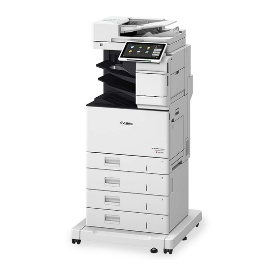
1. Product Overview Product Lineup Host machine without Finisher model with Finisher model Name Control panel Feeder USB port (Front-right side of the machine) Power switch Right cover of the main unit Multi-purpose tray... -
Page 20: Model Type
Glass cleaning sheet storage box Motion sensor Finisher Output tray (Tray A) Model Type Product name imageRUNNER ADVANCE DX C477 The underlined numerical value indicates the print speed (ppm: page per minute) Model DX C477i DX C477iZ DX C477iF DX C477iFZ... -
Page 21: Paper Feed/Output / Image Reading System Options
1. Product Overview Paper Feed/Output / Image Reading System Options Product name ADF Access Handle-A1 Cassette Module-AJ1 Cassette Feeding Unit-AS1 Cassette Feeding Unit-AT1... -
Page 22: Function Expansion System Options
1. Product Overview CAUTION: Combination of installable pickup options 1. Installation of 3 units of [2] Cassette Module-AJ1 is not supported 2. Installation of [3] Cassette Feeding Unit-AS1 and [2] Cassette Module-AJ1 together is not supported 3. Installation of [4] Cassette Feeding Unit-AT1 and [2] Cassette Module-AJ1 together is not supported 4. - Page 23 1. Product Overview Product name Remote Fax Kit-A1 IP FAX Expansion Kit-B1 PCL International Font Set-A1 Picture Login-A1 Barcode Printing Kit-D1 iR-ADV Security Kit-AP1 for IEEE 2600 Common Criteria Certification...
-
Page 24: Product Features
1. Product Overview Product Features New ADF • High Productivity (1-sided / 2-sided), Fastest (Send 300 x 300 dpi) , 100 ipm / 200 ipm , (LTR)95 ipm / 190 ipm (A4) • Small Size Paper-Enabled , Support originals of W 48mm x L 85mm •... -
Page 25: Specifications
1. Product Overview Specifications Host machine Item Specifications Machine installation Desk-top method Photosensitive medi- φ24mm, OPC Exposure method 4Beam Laser Charging method DC Roller Charging Developing method Dry/Single-component Development Transfer method Intermidiate Transfer Belt(ITB) Roller Transfer(Secondary) Separation method Curvature separation Pickup method Stack bypass : Roller separation method Cassette : Lifter + Roller separation method... - Page 26 1. Product Overview Item Specifications Warm-up time Quick start mode:ON • Time until key operations can be performed on the touch panel display: 4 sec or less • Possible to start copying : 10 sec or less Quick start mode:OFF/Non-Quick mode •...
-
Page 27: Fax Specifications
Up to 320 jobs Transmission Times Approximately 2.6 seconds (When sending LTR Canon original paper, Normal 8 pels x 3.85 line/mm, ECM (JBIG)) *1 When using an IP telephone service, facsimile communication may not be performed normally via an IP telephone line. It is recommended to use facsimile communication via a general telephone (Public Switched Telephone Network) line. -
Page 28: Weight And Size
1. Product Overview Weight and Size Product name Width (mm) Depth (mm) Height (mm) Weight: Ap- prox. (kg) imageRUNNER ADVANCE DX C477i 642(when includ- 46*1 642 (when Deck is ing the Control imageRUNNER ADVANCE DX C477iF 46*1 attached) Panel) imageRUNNER ADVANCE DX C477iZ 55*1 749 (when the MP 665 (when Deck is... - Page 29 1. Product Overview Paper type Common (Non-sort mode), * [] indicates the reference value With Finisher only Remark 1-sided 2-sided size Cassette MP Tray Cassette MP Tray Standard Option Standard Option Staple Shift sort mode (5 mode (5 sheets sheets binding) shifting) Thin (60 g/m...
- Page 30 1. Product Overview Paper type Common (Non-sort mode), * [] indicates the reference value With Finisher only Remark 1-sided 2-sided size Cassette MP Tray Cassette MP Tray Standard Option Standard Option Staple Shift sort mode (5 mode (5 sheets sheets binding) shifting) Heavy 2...
-
Page 31: Paper Type
1. Product Overview Paper type Common (Non-sort mode), * [] indicates the reference value With Finisher only Remark 1-sided 2-sided size Cassette MP Tray Cassette MP Tray Standard Option Standard Option Staple Shift sort mode (5 mode (5 sheets sheets binding) shifting) Heavy 5... -
Page 32: Pickup Specifications
1. Product Overview Pickup Specifications Paper type (Pa- Size Feeding direc- Width direction Multi-purpose Cassette 1 Cassette Mod- per weight tion (mm) (mm) Tray ule-AJ1 Cas- g/m2) sette Feeding Unit-AS1 Cas- sette Feeding Unit-AT1 Thin (60) Plain 1 (61 to 75) Plain 2 (76 to 90) Color (61 to 75) Recycled 1 (61 to... - Page 33 1. Product Overview Paper type (Pa- Size Feeding direc- Width direction Multi-purpose Cassette 1 Cassette Mod- per weight tion (mm) (mm) Tray ule-AJ1 Cas- g/m2) sette Feeding Unit-AS1 Cas- sette Feeding Unit-AT1 Plain 3 (91 to 105) FOOLSCAP Bond 1 (60 to 74) (Australia) FOOLSCAP/ 330.2...
- Page 34 1. Product Overview Paper type (Pa- Size Feeding direc- Width direction Multi-purpose Cassette 1 Cassette Mod- per weight tion (mm) (mm) Tray ule-AJ1 Cas- g/m2) sette Feeding Unit-AS1 Cas- sette Feeding Unit-AT1 Heavy 2 (121 to 128) 355.6 215.9 LTRR 279.4 215.9 STMTR...
- Page 35 1. Product Overview Paper type (Pa- Size Feeding direc- Width direction Multi-purpose Cassette 1 Cassette Mod- per weight tion (mm) (mm) Tray ule-AJ1 Cas- g/m2) sette Feeding Unit-AS1 Cas- sette Feeding Unit-AT1 Heavy 3 (129 to LEGAL (India) 163) Custom size 1 127 to 147.9 76.2 to 216 Custom size 2...
-
Page 36: Parts Name
1. Product Overview Parts Name Cross Section View ADF Assembly/Reader Assembly [10] [11] [14] [15] [12] [13] Name ADF Unit Original Tray Pickup Roller Feed Roller Separation Roller After separation feed roller Lead Roller 1 Scanner Unit (Back) Lead Roller 2 [10] Delivery Roller [11]... - Page 37 1. Product Overview Finisher Assembly Name Jogger Guide Y Alignment Roller Exit Feed Roller Inlet Feed Roller Escape Tray Delivery Roller Lower Escape Tray Upper Escape Tray Staple Unit Inlet Flapper...
- Page 38 1. Product Overview Printer Assembly [10] [11] [12] [13] [14] [15] [16] [26] [25] [24] [23] [22] [21] [20] [19] [18] [17] Name Waste Toner Container ITB Unit Primary Transfer Roller ITB Drive Roller Fixing Film Delivery Roller Output accessory flapper Reverse Roller Reverse Flapper [10]...
-
Page 39: Control Panel
1. Product Overview Control Panel Name Touch panel display Main Power indicator Error indicator Processing/Data indicator... -
Page 40: Main Menu
1. Product Overview Main Menu [10] [11] [12] [13] [14] Name Settings/Registration Menu Energy Saver Login Home Timeline Stop Counter Status Check [10] Numeric keys [11] Clear [12] Reset [13] Stop [14] Start Service Buttons Reference figure (Rear side of Control Panel) Name Service Button 1... - Page 41 1. Product Overview Name Service Button 2 Service Button 3 NOTE: Service Buttons are operated by opening the cover. CAUTION: Service Buttons are buttons for service technicians and information is not released to users.
-
Page 42: Technology
Technology Functional Configuration..... 31 Original Exposure System....32 Controller System........55 Laser Exposure System...... 60 Image Formation System....64 Fixing System........82 Pickup Feed System......89 External Auxiliary System....109... -
Page 43: Functional Configuration
2. Technology Functional Configuration This machine consists of 6 major blocks: Original Exposure System, Controller System, Laser Exposure System, Image Formation System, Fixing System, and Pickup/Delivery System. Original Exposure and Feed System Reader Delivery Fixing Fixing System Controller System Image Formation System Deplexing Feed Transfer... -
Page 44: Original Exposure System
2. Technology Original Exposure System Features ■ Reader Assembly • Color reproducibility has been improved by adopting a scanner unit with 3-line CIS installed, as compared with the conventional models. ■ ADF High Productivity (1-sided /2-sided) Fastest (Send 300 x 300 dpi) / Auto Color Select = OFF 100 ipm / 200 ipm (LTR) 95 ipm / 190 ipm (A4) Small Size Paper-Enabled... - Page 45 2. Technology Item Specification/Function Document size • Crosstrack : Up to. 216.0mm • Intrack : Up to. 355.6mm • Automatic Size sensor : No • Size detected by manual operation from panel A4R , A5R , A6R , B5R , LGLR , LTRR , STMTR , 16KR Light source Scan Resolution 600dpi x 600dpi...
-
Page 46: Basic Configuration
2. Technology Item Specification CAUTION Original processing speed • ADF 1-sided (ipm) Auto Color Select=OFF (de- Send (300dpi) fault:USA, EUR) Auto Color Select=OFF Auto Color Select=ON (default:Ex- -BW : A4:95ipm/ LTR:100ipm cept (USA, EUR) ) -CL : A4:95ipm/ LTR:100ipm Auto Color Select=ON -BW : A4:50ipm/ LTR:50ipm -CL : A4:50ipm/ LTR:50ipm Copy(600dpi) - Page 47 2. Technology Name Guide Shaft Drive Pulley Drive Belt Motion Sensor CIS HP Sensor Reader Motor ADF Open/Closed Sensor Scanner Unit (Front) ■ ADF Unit ● Functional Configuration Functional configuration of the ADF in this equipment is shown below. ● Parts Configuration...
- Page 48 2. Technology Symbol Name LED_EXIT Delivery Display LED LED_DS Original Display LED Scanner Unit (Rear Side) CL4200 ADF Pickup Clutch M4201 ADF Motor ● Drive Configuration List The drive assembly of the ADF consists of a ADF Motor, and a Separation Clutch. The drive configuration is indicated below.
-
Page 49: Dust Detection Control
2. Technology Name After separation feed roller After separation feed roller Lead Roller 1 Lead Roller 1 Lead Roller 2 Lead Roller 2 Delivery Roller Delivery Roller ● List of Sensors Symbol Name JUSO(R) Double Feed Detection PCB (Reception) JUSO(T) Double Feed Detection PCB (Transmission) SR4206 Lead Sensor... - Page 50 2. Technology Control timing Dust detection • At job completion Dust evasion • When a job starts Main power Start key switch ON WMUP STBY SCAN SCAN Dust detection Dust avoidance control control Control description At job completion (dust detection) The Reading Sensor performs dust detection at a reading position.
-
Page 51: Image Processing
2. Technology Control Description Guide Plate dust detection/correction is performed with the following steps. 1. A dust detection is performed with a scan before the feed. 2. A dust detection is performed with a scan during the feed. 3. Dust detection correction is performed for the dust that are determined to be adherent to the glass ■... - Page 52 2. Technology • Scanner Unit PCB Driving the Scanner Unit, analog image processing, A/D conversion Image processing is performed line by line for each image with the Main Controller PCB. The main functions are shown below. Main Controller PCB • Shading correction •...
- Page 53 2. Technology Rotation center coordinates Skew amount Extracting the skew amount Detecting and the rotation the edge center coordinates Scanning the original Skew Correction Corrects the skew by rotating the image data according to the detected skew amount. Rotation center coordinates Skew amount Correction...
- Page 54 2. Technology Adjustment of the left edge margin of the scanned image for the corrected image • Adjustment of the left edge margin of the image at DADF reading [front side] FEEDER > ADJUST > ADJ-L1 • Adjustment of the left edge margin of the image at DADF reading [back side] FEEDER >...
- Page 55 2. Technology ■ Color Displacement Correction Processing in Vertical Scanning Direction Color displacement correction control in the vertical scanning direction is used to correct displacement of R, G, and B by shifting the pixels in the vertical scanning direction (by less than 1 pixel) to align the red (R) and blue (B) images with green (G) when the scanned R, G, and B images are not accurately overlapped at color scanning.
-
Page 56: Outline Of Electric Circuits
2. Technology • Adj CIS-ch offset: back,clr mode,300dpi: COPIER > ADJUST > CCD > OFST3CL0: Channel 0 COPIER > ADJUST > CCD > OFST3CL1: Channel 1 COPIER > ADJUST > CCD > OFST3CL2: Channel 2 COPIER > ADJUST > CCD > OFST3CL3: Channel 3 COPIER >... - Page 57 2. Technology Loading original (2 sheets of original) As an example, 2 sheets of original are loaded. Code Name SR4204 Original Sensor SR4205 Pre-separation Sensor Post-separation Sensor JUSO (T) Double Feed Detection PCB (Reception) JUSO (R) Double Feed Detection PCB (Transmission) SR4206 Lead Sensor Reading position for the front side...
- Page 58 2. Technology For the first sheet, from the Post-separation Sensor to the Pullout Roller The picked-up original is fed from the Separation Roller to the Pullout Roller. The Double Feed Sensor located between the Separation Roller and the Pullout Roller detects double feed of original. When conditions are met, the feed is suspended before the original reaches the Pullout Roller.
- Page 59 2. Technology Delivery sequence The second sheet reaches to the temporary stop position and the first sheet is delivered If the paper interval detected with the Post-separation Sensor is less than the specified distance, the second paper is temporarily stopped at the temporary stop position until the paper interval reaches the specified distance. The first sheet that passed through both the front side and back side reading position is delivered to the Delivery Tray at the process speed.
-
Page 60: Scanner Unit
2. Technology Scanner Unit ■ Scanner Unit Configurations The Contact Image Sensor (CIS) is used to expose and read the original, and image reading is performed line by line. Related error codes E280-000x: Scanner Unit communication error • E280-0001: Scanner Unit communication error •... -
Page 61: Pickup Feed System
2. Technology Pickup Feed System ■ Original size detection As this machine does not have a function to detect the length of original, the size of original is calculated based on the time difference between the timings of detection of original by the Post-separation Sensor (REG) and by the Read Sensor (SR4206). Main Controller PCB ... - Page 62 2. Technology • When an original with a width of 105 mm or larger is placed Both the Original Sensor (small size paper) (SR4207) and the Original Sensor (SR4204) detect the original (ON). • When an original with a width of less than 105 mm is placed The Original Sensor (small size paper) (SR4207) detects the original (ON) while the Original Sensor (SR4204) does not detect it (OFF).
- Page 63 2. Technology • When an original is not placed properly If the Original Sensor (small size paper) (SR4207) detects the original (ON) and the Original Sensor (SR4204) detects it (ON) after a short time lag, it is determined that the original was not placed properly. Then, the feed is stopped, and a message that prompts the user to replace the original is displayed.
- Page 64 2. Technology Name Pickup Roller Feed Roller Separation Roller M4201 ADF Motor CL4200 ADF Separation Clutch ■ Jam detection This machine detects original jams using the sensors shown in the figure below. When a jam occurs, the machine records the information as a code. This machine's jam code can be checked in service mode of the host machine or by outputting a jam/error log report from service mode.
- Page 65 2. Technology Code Name Separation Roller Feed Roller Post-Separation Sensor JUSO (R) Double Feed Detection PCB (Reception) JUSO (T) Double Feed Detection PCB (Transmission) After Separation Feed Roller SR4206 Lead Sensor NOTE: The Double Feed Detection PCBs use an ultrasonic sensor. With the ultrasonic method, the oscillation portion emits ultrasonic wave and applies it to paper surface.
- Page 66 2. Technology Location Jam code Jam type Sensor name Sensor number Post-Separation Sensor 0042 Stationary 0009 Delay Lead Sensor 0049 Delay 0010 Stationary 0050 Stationary 0013 Delay Delivery Sensor SR4206 0014 Stationary 0016 Early timing 0053 Delay 0054 Stationary ● Double Feed Detection Location Jam code Jam type...
-
Page 67: Controller System
2. Technology Controller System Overview ■ Configurations/Functions Main Controller PCB TPM PCB Flash PCB Item Functions Main Controller PCB System Control/Memory Control/Printer Output Image Processing Control, Reader Image Input Processing, Fax Image Processing, Voice Operation/Voice Guidance Connection I/F, Card Reader Connection I/F, USB Extension HUB Connection I/F RAM: 4GB Temporary storage for image data: 2 GB (for controller control) + 2 GB (for image processing) capacity... - Page 68 2. Technology ■ Main Controller PCB J4503 J4514 Roles and Specifications TPM PCB USB TypeB USB3.0 LAN I/F Flash PCB Controller Fan Connector for options (Serial Interface Kit, etc.) CC-VI: Control Interface Kit I/F J4000 Not used J4001 Reader CIS J4002 ADF CIS J4003...
-
Page 69: Startup Sequence
2. Technology Roles and Specifications J4516 For USB Connecter J6000 Not used J6003 HDD I/F (Serial) J6004 For HDD power supply J6005 FRAM PCB J6010 IJ WIFI J9000 DC Controller PCB (VIF-FFC-OIP) J9001 DC Controller PCB (CONT-DCC-IF-CABLE) Startup Sequence Power Supply Switch ON Power Supply Switch ON Initializing process of hardware... -
Page 70: Shutdown Sequence
2. Technology NOTE: When the following errors occur, the system of the host machine has not been started normally. Therefore the error code is not recorded in the log. E602-XX01, E614-XX01, E748-2010 Shutdown Sequence Before shutting down the power supply, it is necessary to perform the HDD completion process (Purpose: to prevent damage on the HDD) and execute the fixing disengagement operation. - Page 71 2. Technology CAUTION: • The motion sensor detects people or objects that approach the sensor on the front side of the machine. Operation may become unstable if objects are left near the sensor or the machine is placed in a location where there is heavy human traffic.
-
Page 72: Laser Exposure System
2. Technology Laser Exposure System Overview The laser exposure system forms a static latent image on the Photosensitive Drum by laser exposure. The Laser Scanner Unit consists of the Laser Assembly and the Scanner Motor, and is controlled by the signal input from the DC Controller PCB. -
Page 73: Apc (Auto Power Control)
2. Technology Execution timing At power-on, and at printing Control description The Scanner Motor rotation speed is controlled by the DC Controller PCB. 1. The DC Controller PCB outputs Scanner Motor control signals (acceleration signals and deceleration signals) to the Scanner Motor to rotate the Polygon Mirror. -
Page 74: Bd Detection Correction Control
2. Technology 2. The APC mode is set for the Laser Driver ICs of each Laser Driver PCB and the laser diode of each color is forcibly activated. The photo diode (PD) monitors the laser diode (LD), and each Laser Driver IC adjusts the output of laser diode until the laser light intensity reaches a specified level. - Page 75 2. Technology START Scanner motor control finish BD interval (Constant-speed rotation detection) Specified value BD interval measurement Before correction Write start position correction value calculation Write start position After correction value correction...
-
Page 76: Image Formation System
2. Technology Image Formation System Overview The image formation system creates a toner image on the paper. The image formation system consists of the followings: • Cartridge • Primary Transfer Roller • Secondary Transfer Roller • Fixing Assembly • Laser Scanner Unit •... - Page 77 2. Technology Load drives of electrical components DC Controller Electric Name code Yellow drum, yellow developer and magenta developer Motor Magenta drum, cyan drum and cyan developer Motor Black drum, black developer and ITB Motor Fixing Motor Developer alienation motor...
- Page 78 2. Technology Outline drawing of sensors ITB Residual Toner Collection Box Full Sensor Registration Patch Sensor SR51 Y Toner Level SR52 Sensor M Toner Environment Level SR54 Sensor Sensor C Toner Level Sensor SR53 K Toner Level Sensor DC Controller Electric Name code...
- Page 79 2. Technology : Paper path Delivery : Direction of drum rotation : Functional block Fixing 8. Fixing : Step ITB cleaning Transfer 7. Separation 9. ITB cleaning 6. Secondary transfer Developing 5. Primary transfer 4. Developing Drum cleaning 10. Drum cleaning 3.
- Page 80 2. Technology Primary charging roller Primary charging bias Photosensitive drum Step 3: Laser beam exposure In this step, a static latent image is formed on the Photosensitive Drum by the laser beam. When the negatively charged Photosensitive Drum is scanned by the laser beam, the negative charge is neutralized and this area turns into a static latent image.
- Page 81 2. Technology ● Transfer Block This block consists of 3 steps, and transfers the toner image on the Photosensitive Drum surface to the paper. Step 5: Primary transfer In this step, toner on the Photosensitive Drum is transferred to the ITB. Primary transfer bias is applied to the Primary Transfer Roller in order to attract toner to the ITB.
- Page 82 2. Technology Paper Static Charge Eliminator Secondary Transfer Roller ● Fixing Block In this block, the toner image is fixed on the paper. Step 8: Fixing In this step, the toner image on the paper is fixed on the paper by applying pressure and heat. Fixing bias is applied to the Pressure Roller in order to improve the image quality.
-
Page 83: Cartridge
2. Technology Residual Toner feed screw T1 roller Cleaning blade ITB cleaning brush Photosensitive drum ITB brush bias T1 bias ● Drum Cleaning Block This block cleans residual toner on the Photosensitive Drum. Step 10: Drum cleaning This step uses the Cleaning Blade to scrape off the residual toner on the surface of the Photosensitive Drum and collects the toner. - Page 84 2. Technology DC Controller SR54 SR51/SR52/SR53 Developer alienation sensor Drum Home Position Sensor 1/2/3 Photosensitive Drum Memory Tag Developing Assembly M1/M2/M3 Drum Motor Primary Charging Roller Developing Roller Cartridge The cartridge of this machine consists of the Photosensitive Drum, Developing Assembly, Primary Charging Roller, Memory Tag, etc.
- Page 85 2. Technology Display when wrong color is detected Display when a non-genuine part is detected or a failed cartridge is detected Description A cartridge of this machine is equipped with the cartridge memory and by reading its information, the status of cartridge is detected. Execution timing •...
- Page 86 2. Technology • Check on the Control Panel Status Monitor > Consumables/Others > Check Consumables • Check in the service mode COPIER > COUNTER > LIFE > TONER-Y COPIER > COUNTER > LIFE > TONER-M COPIER > COUNTER > LIFE > TONER-C COPIER >...
- Page 87 2. Technology Names of Remaining Toner Low in Toner Container Output Stop Replacement Comple- Condition tion Display/Hide Hide Display Hide Display* message Message (ma- Cyan toner is low. Replacement is not Replace the toner cartridge. (Cyan) chine opera- yet needed. Replace the toner cartridge.
- Page 88 2. Technology • 10-0100-0074: (C) Unidentified Toner Bottle detection (each color) • 10-0100-0181: (Bk) • 10-0100-0182: (Y) • 10-0100-0183: (M) • 10-0100-0184: (C) ■ Developing Assembly Engagement/Disengagement Control The Developing Assembly engagement/disengagement control is used to engage/disengage the Developing Assembly with/from the Photosensitive Drum as needed depending on the specified print mode (full color/black and white).
-
Page 89: Transfer
2. Technology Transfer ■ Overview The ITB Unit performs primary transfer of a toner image on the Photosensitive Drum onto the ITB. The internal structure of the ITB Unit is as follows. • ITB (Intermediate Transfer Belt) • ITB Drive Roller •... - Page 90 2. Technology DC controller Fixing motor Primary transfer roller control signal disengagement detection signal <When four drums are disengaged> Fixing Motor Primary transfer roller ITB Pressure disengagement Release Sensor solenoid control signal SR1901 Primary Transfer Disengagement Solenoid Photosensitive Drum <When four drums are engaged> Primary Transfer Roller Primary Transfer Roller Disengagement Cam...
- Page 91 2. Technology ■ ITB Blade Cleaning Mechanism The ITB Cleaner cleans the ITB surface. Waste toner that remains on the ITB surface is scraped by the Cleaning Blade in the Cleaner. Waste toner is fed to the Waste Toner Container by the Waste Toner Feed Screw in the Cleaner. DC Controller Cleaning Blade ITB Cleaner...
-
Page 92: Image Stabilization Control
2. Technology *1: The notification timing and display/hide for the Waste Toner Container Advance Notice Alarm can be set by the following service mode. COPIER > OPTION > PM-DLV-D > WST-TNR *2: Whether to display/hide the Waste Toner Container preparation warning message can be specified in the following service mode. - Page 93 2. Technology ■ Image Density Correction Control • Image Gradation Correction Control (D-half) This is a control where the Main Controller PCB performs gradation correction based on the measurement results of the halftone density performed by the DC Controller PCB. The DC Controller PCB and Main Controller PCB perform D-half control in the order shown below.
-
Page 94: Fixing System
2. Technology Fixing System Overview Fixing Delivery Assembly consists of the Fixing Assembly for fixing toner on the print paper and the Delivery Assembly for delivering print paper on which toner is fixed to the Delivery Outlet. Main Parts in the Fixing Assembly This circuit is for controlling the temperature of the Fixing Assembly. -
Page 95: Fixing Temperature Control
2. Technology Symbol Parts name Function/Method Thermoswitch This is engaged with Heater. AC power supply is shut down at detection of a failure. Fixing Temperature Control This control detects the surface temperature of the Fixing Heater and controls the drive signal of the Fixing Heater so that the temperature of the Fixing Heater becomes the target temperature. - Page 96 2. Technology Related error code • E000-0001 Fixing Assembly: Temperature rise failure • E001-0001 Fixing Main Thermistor high temperature detection error • E001-0002 Fixing Sub Thermistor (Rear) high temperature detection error • E001-0004 Fixing Sub Thermistor (Front) high temperature detection error •...
-
Page 97: Fixing Pressure/Disengagement Control
2. Technology For the print speed during this control, refer to “Productivity” on page Fixing Pressure/Disengagement Control The Fixing Film Unit is disengaged from the Pressure Roller under a specific condition in order to improve jam removability. Fixing Pressure Fixing Pressure Release Sensor Release Sensor (SR8612) - Page 98 2. Technology Pressure Roller Loop Sensor (SR8615) Fixing Film Sensor flag Secondary Transfer Outer Roller Control description Since the feeding speed of the Pressure Roller and that of the Secondary Transfer Outer Roller are not the same when paper is fed to the Fixing Assembly, image failure, paper wrinkle, image stretching, etc.
-
Page 99: Protection Function
2. Technology 5. Repeat step 1 to 4 in the case of continuous printing. For single-sheet printing, the Fixing Motor (M4) is stopped after the trailing edge of the paper passes through the Delivery Sensor. The machine goes to the last rotation operation in the case of small size paper. - Page 100 2. Technology Code Details Title Detail E001 Abnormally high fixing 0004 The Sub Thermistor (Front) detected temperature of specified value or higher temperature detection E003 0001 Abnormally low fixing tem- The Main Thermistor detected temperature of specified value or lower perature detection 0002 The Sub Thermistor (Rear) detected temperature of specified value or lower...
-
Page 101: Pickup Feed System
2. Technology Pickup Feed System Overview Standard model Finisher model... -
Page 102: Specification
2. Technology Parts name Delivery Assembly Duplex Reverse Area Fixing/Registration Assembly Multi-purpose Tray Pickup Assembly Cassette Pickup Assembly Specification Item Specifications Pickup Method Stack bypass : Roller separation method Cassette : Lifter + Roller separation method Paper stack capacity • Stack bypass : 100 sheets(75g/m 90 sheets(80g/m 10 sheets(Envelope) - Page 103 2. Technology Symbol Parts name Upper Escape Tray Delivery Roller Y Alignment Roller Exit Feed Roller Inlet Feed Roller Lower Escape Tray Delivery Roller Printer Assembly Roller Locations [13] [12] [11] [10]...
- Page 104 2. Technology Symbol Parts name Output roller Reverse Roller Secondary Transfer Outer Roller Duplex Feed Upper Roller Registration Shutter Registration Roller Multi-purpose Tray Pickup Roller Multi-purpose Tray Separation Roller Duplex Re-pickup Roller Intermediate Feed Roller Cassette 1 Separation Roller Cassette 1 Pickup Roller Cassette 1 Feed Roller ■...
- Page 105 2. Technology Symbol Name PS211 Finisher Tray Upper Limit Sensor PS212 Finisher Tray Lower Limit Sensor Printer Assembly SR62 SR8611/8613 SR8615 SR12/13 SR94 SR11 SR95 SR14 Symbol Name SR11 Pre-Registration Sensor SR12 Registration media width sensor (Front) SR13 Registration media width sensor (Rear) SR14 Cassette1 Paper Sensor SR8615...
- Page 106 2. Technology Symbol Name SS Feed Motor Jogger Guide Motor Staple Motor SL21 Inlet Flapper Solenoid SL23 Lower Escape Tray flapper solenoid Upper Escape Tray Shift Motor Staple Stacker Output Motor Y Alignment Motor SL22 Stanp Solenoid Printer Assembly...
- Page 107 2. Technology Symbol Name Cassette1 Pickup_Feed Clutch Duplex re-pickup clutch Multi-purpose Tray Pickup Solenoid Pickup_Registration Motor Reverse Solenoid Reverse Motor Black drum, black developer and ITB Motor Fixing Motor...
- Page 108 2. Technology ■ Paper Path Finisher Assembly...
-
Page 109: Cassette Pickup Assembly
2. Technology Printer Assembly Cassette Pickup Assembly ■ Paper Size Detection Control A4, A5R, B5R, LGL, and LTRR are automatically detected by combining a series of the Cassette Size Switches (SW5). The SW5 controls ON/OFF by the Link Arm of the Side Guide Plate. - Page 110 2. Technology CAUTION: Follow the procedure shown below to set the paper size of A5, A6R, 16KR, STMTR, or EXER because those sizes cannot be automatically detected. Select Settings/Registration > Preferences > Paper Settings > Paper Settings > Select This Cassette > Unrecognized Standard Size >...
- Page 111 2. Technology ■ Cassette Pickup Control The DC Controller controls the Pickup_Registration Motor (M5) and Cassette1 Pickup_Feed Clutch (CL1) to feed paper and the Cassette Separation Roller to prevent double feeding. The Cassette Separation Rollers are driven and rotated by the Cassette Feed Roller. Operation of Cassette Separation Roller Feed roller Separation roller...
-
Page 112: Multi-Purpose Tray Pickup Assembly
2. Technology SR14 When paper inside a Cassette is lifted up by the Lifter Plate and paper surface reaches the position of the Pickup Roller, the Cassette1 Paper Sensor (SR14) is turned ON to detect that the paper has reached the pickup position. If paper is in the Cassette at this time, paper pickup becomes possible. -
Page 113: Registration Assembly
2. Technology Symbol Parts name Multi-purpose Tray Pickup Roller Multi-purpose Tray Separation Roller Multi-purpose Tray Pickup Solenoid Pickup_Registration Motor Registration Assembly Registration Control This control stops paper at the registration position, aligns paper and image on the drum at the specified timing, and feed paper. Skew Correction Control The paper leading edge runs into the Registration Shutter in a halted state, thereby forming a slack (arch) to correct the skew. -
Page 114: Process Tray Assembly (Built-In Finisher Machine Only)
2. Technology Service mode • Adjustment of registration start timing (Plain paper) COPIER > ADJUST > FEED-ADJ > REGIST • Adjustment of registration start timing (Plain paper, 2nd side) COPIER > ADJUST > FEED-ADJ > REG-DUP1 • Adjustment of registration start timing (Multi-purpose Tray, Plain paper) COPIER >... - Page 115 2. Technology • E577-8001: Y Alignment Motor error ■ Stapling operation Overview Stapling is the operation to staple the specified number of sheets of paper together. Staple Unit Paper Staple Unit The Staple Motor drives the cam to perform stapling. The Staple HP Sensor detects the cam's home position.
-
Page 116: Stack Tray Assembly (Model With Built-In Finisher Only)
2. Technology Upper Escape Tray Delivery Upper Roller Upper Escape Tray Delivery Lower Roller PS206 Disengagement Cam [Engagement] [Disengagement] Delivery Upper Roller Disengagement PS206 Sensor : OFF Sensor : ON Related error codes • E568-8001: Stack Delivery Roller disengagement error Stack Tray Assembly (Model with Built-in Finisher Only) ■... - Page 117 2. Technology PS211 PS201 PS212 PS201 PS211 PS212 ■ Tray Paper Full Detection The Upper Escape Tray Media Full Sensor (PS205) detects the paper stack full of Upper Escape Tray. The Lower Escape Tray Media Full Sensor (PS209) detects the paper stack full of Lower Escape Tray. PS205 PS209...
-
Page 118: Delivery Assembly
2. Technology Delivery Assembly Delivery Full Detection The Delivery Paper Full Sensor (SR42) detects delivered paper as full after detecting paper delivery for a certain period of time. After detecting full, printing stops. Reverse/Duplex Assembly Duplex Reverse Control The paper reverse operation is performed with the feed path switching from the Delivery Outlet to Reverse Mouth by the operation of the Reverse Flapper. - Page 119 2. Technology PS202 PS203 PS210 Symbol Name PS202 Staple Stacker Outlet Sensor PS203 Staple Inlet Sensor PS210 Staple Stacker Inlet Sensor Printer Assembly SR62 SR8611/8613 SR8615 SR12/13 SR94 SR11 Symbol Name SR11 Pre-Registration Sensor SR12 Registration media width sensor (Front) SR13 Registration media width sensor (Rear) SR8615...
- Page 120 2. Technology Symbol Name SR8611 Fuser output sensor 1 SR8613 Fuser output sensor 2 SR62 Delivery Paper Full Sensor SR94 Duplex Sensor...
-
Page 121: External Auxiliary System
2. Technology External Auxiliary System Software counter This machine has software counters which count the number of prints/copies according to the job type. Various counters are displayed by pressing the Check Counter key on the Control Panel. The default counters for each country/region (model) are listed below. - Page 122 2. Technology Target Display number of each counter (in service mode) / item Region Code Counter 1 Counter 2 Counter 3 Counter 4 Counter 5 Counter 6 Counter Counter 8 220V Total Total (Full Scan (Total Print (Total GER model (Black/ Color + Sin- type 1...
-
Page 123: Fan
2. Technology Region code Region Region code Region Region code Region Korea Slovenia India China Greece Taiwan Estonia ■ Count-up timing Count-up timing differs according to the following: • Print mode (1-sided print/2nd side of 2-sided print, 1st side of 2-sided print) •... - Page 124 2. Technology Name Role Type Speed FM7 Power Supply, Main Controller PCB Cooling To cool the Power Supply PCB and Main Controller Suction Full speed/Half area speed Error Code • E804-0000 Power Supply Cooling Fan error • E805-0001 Power Supply Cooling Fan error •...
-
Page 125: Power Supply
2. Technology Power supply ■ Internal power supply AC input Fuse DC controller PCB FU100 Fuser Fuse FU101 Low-voltage power supply /ZEROX Zero crossing +3.3VB2 detection circuit PFC_RMT 24V_RMT +3.3VB +24V +24VA Rectifying generation +24VB circuit circuit Protection 24V interlock +3.3VC circuit switch... - Page 126 2. Technology Reader Control panel State of power supply ON Standby Energy Saving State of power supply OFF Engine Main Controler [Energy Saver] key [Energy Saver] key A specified period of time has passed Sleep Mode Sleep Standby Energy Use Energy Use “Low”...
-
Page 127: Quick Startup
2. Technology Sleep Exit The machine first enters this mode when returning to Standby from Sleep. The state where power supply is maintained to return from Sleep. Deep Sleep The state where the Control Panel is turned OFF and only the All-night Power (5 V) is supplied. The machine enters this mode from Sleep Standby during Sleep. - Page 128 2. Technology Even when the Main Power Supply Switch is OFF, power is supplied to the following PCBs: Quick startup setting ON Quick startup setting OFF Low-voltage Power Supply PCB Output: ON Output: ON Main Controller PCB Output: ON Output: OFF NOTE: The quick startup function can be set from "Settings/Registration".
-
Page 129: Technical Explanation (System)
Technical Explanation (System) Overview........... 118... -
Page 130: Overview
3. Technical Explanation (System) Overview For following items, refer to the "imageRUNNER ADVANCE V3.x System Service Manual". • System Management • Authentication • Security Function • Firmware Management • Management of System Options • MEAP Application Management • Backup/Restoration • Monitoring ( e-Maintenance/imageWARE Remote ) Function... -
Page 131: Periodical Service
Periodical Service Periodically Replacement Parts..120 Consumable parts......121... -
Page 132: Periodically Replacement Parts
4. Periodical Service Periodically Replacement Parts There are no periodically replacement parts in this machine. -
Page 133: Consumable Parts
4. Periodical Service Consumable parts Name Parts num- Estimated Work Service mode Alarm code (Re- Notes cate- placement com- ber* life* Parts counter Life value gory pletion) COUNTER > COUNTER > DRBL1/2 LIFE 1 Fixing Unit FM1-W274 150,000 pages FX-UNIT 43-0076 (120V) place-... -
Page 134: Parts Replacement And Cleaning
Parts Replacement and Cleaning Preface..........123 List of Parts........124 External Cover/Interior System..146 External / Internal Cover System (Finisher)........162 Original Exposure/Feed System..173 Controller System......214 Controller System (Finisher)..... 238 Laser Exposure System....239 Image Formation System....241 Fixing System........251 Removing the Fixing Motor.... -
Page 135: Preface
5. Parts Replacement and Cleaning Preface Outline This chapter describes disassembly and assembly procedures of the host machine. The service technician is to identify the cause of host machine failures according to follow the disassembly procedures of each part to replace the defective parts or the consumable parts. -
Page 136: List Of Parts
5. Parts Replacement and Cleaning List of Parts External / Internal Cover ■ Host Machine (For Models with the Finisher) [10] [11] [12] Name Front Cover Cassette 1 Right Lower Cover Right Door Unit Right Rear Cover Control Panel Upper Cover Staple Cover Finisher Right Upper Cover Finisher Right Rear Cover... - Page 137 5. Parts Replacement and Cleaning [11] [12] [10] [14] [13] [15] Name Left Door Left Lower Cover Left Rear Cover Rear Cover Finisher Rear Cover Finisher Left Rear Cover Delivery Tray Finisher Inner Rear Cover 2 Bin Rear Cover [10] StackingWall Unit [11] Jogger Cover...
- Page 138 5. Parts Replacement and Cleaning ■ Host Machine (For Models without the Finisher) Name Front Cover Cassette 1 Right Lower Cover Right Door Unit Right Rear Cover Right Upper Cover Control Panel Upper Cover Front Upper Cover...
- Page 139 5. Parts Replacement and Cleaning Name Left Door Left Lower Cover Left Rear Cover Rear Cover Delivery Tray Inner Delivery Rear Cover Front Cover Left Inner Delivery Right Upper Cover Inner Delivery Sub Cover ■ ADF Name Original Tray ADF Base Feeder Cover ADF Rear Cover ADF Side Guide Plate...
- Page 140 5. Parts Replacement and Cleaning ■ Reader Name Copyboard Glass Unit Glass Cleaning Sheet Storage Box Reader Rear Upper Cover Reader Cable Cover Reader Rear Cover 1 Reader Rear Cover 2 Reader Motor Cover...
-
Page 141: Main Unit
5. Parts Replacement and Cleaning Main Unit ■ Host Machine Name Delivery Unit Fixing Assembly Secondary Transfer Unit Registration Unit Fixing Drive Unit Main Drive Unit Pickup Drive Unit Lifter Drive Unit Laser Scanner Unit... - Page 142 5. Parts Replacement and Cleaning [11] [10] [12] [13] [14] [15] Name [10] ITB Unit [11] Control Panel Unit [12] Color Displacement Density Sensor Unit/ Registration Patch Sensor Unit [13] Pickup Unit [14] Waste Toner Container [15] Low-voltage Power Supply Unit...
- Page 143 5. Parts Replacement and Cleaning Name Jogger Unit Upper Paper Feed Unit Staple Unit Lower Paper Feed Unit ■ ADF Name ADF Unit Scanner Unit (Back) Separation Unit Pickup Unit...
-
Page 144: Electrical Components List
5. Parts Replacement and Cleaning ■ Reader Name Reader Unit Scanner Unit (Front) Electrical Components List ■ Printer ● PCB UN28,29 UN30,31 UN36 UN21 UN37 UN22 UN7,8 UN11... - Page 145 5. Parts Replacement and Cleaning Name Main Controller PCB UN7, 8 Low-voltage Power Supply PCB Control Panel Main PCB UN11 Environment Sensor PCB UN21 Fuser PCB UN22 Fuser Sub PCB UN28,29 Modular PCB UN30,31 FAX PCB UN36 Motion Sensor UN37 Control Panel LED PCB Touch Panel Wireless LAN PCB...
- Page 146 5. Parts Replacement and Cleaning Name UN24 Drum Unit Memory PCB UN25 Drum Unit Memory PCB UN26 Drum Unit Memory PCB ● Sensor SR1901 SR8613 UN21 SR8612 SR8615 SR11 SR12 SR13 SR14 Name SR11 Pre-Registration Sensor SR12 Registration media width sensor (Rear) SR13 Registration media width sensor (Front) SR14...
- Page 147 5. Parts Replacement and Cleaning SR51 SR52 SR66 SR53 SR62 SR54 SR94 SR95 Name SR51 Drum Home Position Sensor Y SR52 Drum Home Position Sensor MC SR53 Drum Home Position Sensor Bk SR54 Developer Alienation Sensor SR62 Delivery Paper Full Sensor SR66 Reverse Flapper Position Sensor SR94...
- Page 148 5. Parts Replacement and Cleaning ● Solenoid/Clutch Name Primary Transfer Disengagement Solenoid Multi-purpose Tray Pickup Solenoid Reverse Solenoid Cassette1 Pickup_Feed Clutch Duplex re-pickup Clutch...
- Page 149 5. Parts Replacement and Cleaning ● Switch / Heater / Speaker SW10 Name 24V Interlock Switch ITB toner collection near full Switch 5V interlock Switch Cassette 1 Size Switch 24V Interlock Switch SW10 Main Power Switch...
- Page 150 5. Parts Replacement and Cleaning H1,H2 TH_R TH_C TH_F Name Fixing Main Heater Fixing Sub Heater TH_F Sub Thermistor (Front) TH_C Main Thermistor TH_R Sub Thermistor (Rear) Thermoswitch Control Panel Speaker FAX Speaker...
- Page 151 5. Parts Replacement and Cleaning ● Fan FAN11 Name Power Supply Cooling Fan Cartridge Cooling Fan Left Upper Front Fan Left Upper Rear Fan Fuser Fan Power Supply,Main Controller PCB Cooling Fan FAN11 Controller Fan...
- Page 152 5. Parts Replacement and Cleaning ● Motor SL21 SL23 SL22 Name Yellow drum,yellow developer and magenta developer Motor Magenta drum,cyan drum and cyan developer Motor Black drum, black developer and ITB Motor Fixing Motor Pickup Motor Developing Alienation Motor Laser Scanner Motor Delivery Motor...
- Page 153 5. Parts Replacement and Cleaning ■ Finisher ● Sensor (Finisher) PS205 PS204 PS207 PS206 PS203 PS201 PS202 PS209 PS212 PS208 PS211 PS210 Name PS201 Finisher Tray Paper Sensor PS202 Staple Stacker Outlet Sensor PS203 Staple Inlet Sensor PS204 Y Alignment HP Sensor PS205 Finisher Tray Paper Full Sensor PS206...
- Page 154 5. Parts Replacement and Cleaning ● Motor (Finisher) SL21 SL23 SL22 Name SS Output Motor SS Feed Motor Jogger Motor Y Alignment Motor Staple Motor Lifter Motor SL21 Output Solenoid SL22 Stamp Solenoid SL23 2Bin Output Solenoid...
- Page 155 5. Parts Replacement and Cleaning ● Others (Finisher) FAN21 SW21 Name FAN21 Finisher Fan Finisher Door Switch SW21 Finisher Interlock Switch Finisher Controller PCB Reader Relay PCB...
- Page 156 5. Parts Replacement and Cleaning ■ ADF SR4205 SR4207 M4201 CL4200 SR4204 SR4206 LED_EXIT JUSO(T) LED_DS JUSO(R) Name Delivery Sensor ADF Cover Sensor SR4204 Original Senser SR4205 Pre-Separation Sensor SR4206 Read Sensor SR4207 Original Senser (small size paper) Post-Separation Sensor JUSO(R) Double Feed Detection PCB (Reception) JUSO(T)
- Page 157 5. Parts Replacement and Cleaning ■ Reader M4100 Name CIS HP Sensor ADF Open/Closed Sensor M4100 Reader Motor...
-
Page 158: External Cover/Interior System
5. Parts Replacement and Cleaning External Cover/Interior System Removing the Rear Cover ■ Preparation “ Removing the Finisher Rear Cover” on page 162 ■ Procedure(Without Finisher Model) -
Page 159: Removing The Front Cover
5. Parts Replacement and Cleaning Removing the Front Cover ■ Preparation “ Removing the Cassette1” on page 161 ■ Procedure... -
Page 160: Removing The
5. Parts Replacement and Cleaning Removing the Front Cover ■ Preparation “ Removing the Control Panel Upper Cover” on page 157 ■ Procedure... -
Page 161: Removing The Front Cover Left
5. Parts Replacement and Cleaning Removing the Front Cover Left ■ Preparation “ Removing the Control Panel Upper Cover” on page 157 “Removing the Front Cover” on page 148 ■ Procedure Removing the Right Rear Cover ■ Preparation “ Removing the Finisher Rear Cover” on page 162 “... -
Page 162: Removing The Right Upper Cover
5. Parts Replacement and Cleaning Removing the Right Upper Cover ■ Preparation “ Removing the Control Panel Upper Cover” on page 157 “Removing the Front Cover” on page 148 ■ Procedure Removing the Right Lower Cover ■ Preparation “ Removing the Cassette1” on page 161 “... -
Page 163: Removing The Right Door Unit
5. Parts Replacement and Cleaning ■ Procedure Removing the Right Door Unit ■ Procedure... - Page 164 5. Parts Replacement and Cleaning...
-
Page 165: Removing The Left Door
5. Parts Replacement and Cleaning Removing the Left Door ■ Preparation “ Removing the Waste Toner Container” on page 161 ■ Procedure Removing the Left Rear Cover ■ Preparation “ Removing the Finisher Rear Cover” on page 162 “ Removing the Rear Cover” on page 146... -
Page 166: Removing The Left Lower Cover
5. Parts Replacement and Cleaning ■ Procedure Removing the Left Lower Cover ■ Preparation “ Removing the Cassette1” on page 161 “ Removing the Finisher Rear Cover” on page 162 “ Removing the Rear Cover” on page 146 “Removing the Left Rear Cover” on page 153 “Removing the Finisher Left Rear Cover”... -
Page 167: Removing The Inner Delivery Rear Cover
5. Parts Replacement and Cleaning ■ Procedure Removing the Inner Delivery Rear Cover ■ Preparation “ Removing the Rear Cover” on page 146 “Removing the Left Rear Cover” on page 153 ■ Procedure Removing the Inner Delivery Right Upper Cover ■... - Page 168 5. Parts Replacement and Cleaning ■ Procedure...
-
Page 169: Removing The Control Panel Upper Cover
5. Parts Replacement and Cleaning Removing the Control Panel Upper Cover ■ Procedure Removing the Delivery Tray ■ Procedure “ Removing the Control Panel Upper Cover” on page 157 “ Removing the Rear Cover” on page 146 “Removing the Main Controller Sub Cover /Main Controller Cover” on page 214 “... - Page 170 5. Parts Replacement and Cleaning “Removing the ITB Unit” on page 246 “ Removing the Waste Toner Container” on page 161 ■ Procedure...
- Page 171 5. Parts Replacement and Cleaning...
- Page 172 5. Parts Replacement and Cleaning...
-
Page 173: Removing The Waste Toner Container
5. Parts Replacement and Cleaning Removing the Waste Toner Container ■ Procedure NOTE: When the consumable parts have been replaced, be sure to initialize the parts counter of the replaced parts in the following service mode. • COPIER > COUNTER > DRBL-1 > WST-TNR Removing the Cassette1 ■... -
Page 174: External / Internal Cover System (Finisher)
5. Parts Replacement and Cleaning External / Internal Cover System (Finisher) Removing the Finisher Rear Cover ■ Procedure Removing the Finisher Right Upper Cover ■ Preparation “ Removing the Control Panel Upper Cover” on page 157 “Removing the Front Cover” on page 148... -
Page 175: Removing The Finisher Right Rear Cover
5. Parts Replacement and Cleaning ■ Procedure Removing the Finisher Right Rear Cover ■ Preparation “Removing the Staple Cover” on page 166 “Removing the Staple Inner Cover” on page 166 “Removing the Finisher Right Upper Cover ” on page 162 “... -
Page 176: Removing The Finisher Right Door
5. Parts Replacement and Cleaning “Removing the Finisher Right Rear Cover” on page 163 ■ Procedure Removing the Finisher Right Door ■ Preparation “Removing the Staple Cover” on page 166 “Removing the Staple Inner Cover” on page 166 “Removing the Finisher Right Upper Cover ” on page 162 “... -
Page 177: Removing The Finisher Left Rear Cover
5. Parts Replacement and Cleaning NOTE: バネの取付けは、下図の手順で取り付けること 。 Removing the Finisher Left Rear Cover ■ Preparation “ Removing the Finisher Rear Cover” on page 162... -
Page 178: Removing The Staple Cover
5. Parts Replacement and Cleaning ■ Procedure Removing the Staple Cover ■ Procedure Removing the Staple Inner Cover ■ Preparation “Removing the Staple Cover” on page 166... -
Page 179: Removing The Finisher Inner Rear Cover
5. Parts Replacement and Cleaning ■ Procedure Removing the Finisher Inner Rear Cover ■ Preparation “ Removing the Finisher Rear Cover” on page 162 “ Removing the Rear Cover” on page 146 “Removing the Finisher Left Rear Cover” on page 165 “Removing the Left Rear Cover”... -
Page 180: Removing The Finisher Delivery Tray
5. Parts Replacement and Cleaning ■ Procedure Removing the Finisher Delivery Tray ■ Procedure “ Removing the Control Panel Upper Cover” on page 157 “Removing the Staple Cover” on page 166 “ Removing the Finisher Rear Cover” on page 162 “... -
Page 181: Removing The Jogger Cover
5. Parts Replacement and Cleaning ■ Procedure Removing the Jogger Cover ■ Preparation “ Removing the Control Panel Upper Cover” on page 157 “Removing the Staple Cover” on page 166... -
Page 182: Removing The Inner Delivery Rear Cover
5. Parts Replacement and Cleaning ■ Procedure Removing the Inner Delivery Rear Cover ■ Preparation “ Removing the Rear Cover” on page 146 “Removing the Left Rear Cover” on page 153 “ Removing the Finisher Rear Cover” on page 162 “Removing the Finisher Left Rear Cover”... -
Page 183: Removing The Finisher Inner Rear Cover
5. Parts Replacement and Cleaning NOTE: Check the position of the claw in the figure Removing the Finisher Inner Rear Cover ■ Preparation “ Removing the Rear Cover” on page 146 “Removing the Left Rear Cover” on page 153 “ Removing the Finisher Rear Cover” on page 162 “Removing the Finisher Left Rear Cover”... - Page 184 5. Parts Replacement and Cleaning NOTE: Check the position of the claw in the figure.
-
Page 185: Original Exposure/Feed System
5. Parts Replacement and Cleaning Original Exposure/Feed System Removing the ADF Unit/the Reader Unit ■ Preparation “ Removing the Control Panel Upper Cover” on page 157 “ Removing the Finisher Rear Cover” on page 162 “ Removing the Rear Cover” on page 146 “Removing the Main Controller Sub Cover /Main Controller Cover”... - Page 186 5. Parts Replacement and Cleaning...
-
Page 187: Removing The Adf
5. Parts Replacement and Cleaning Removing the ADF ■ Preparation “ Removing the Rear Cover” on page 146 ■ Procedure (For Models without the Finisher) CAUTION: Be careful not to damage the white sheets and the White Plate of the ADF Unit when disassembling/assembling. - Page 188 5. Parts Replacement and Cleaning...
- Page 189 5. Parts Replacement and Cleaning...
- Page 190 5. Parts Replacement and Cleaning CAUTION: When installing the ADF Unit, be sure to insert the rib of the Harness Cover into the guide of the Reader Unit. ■ Preparation (For Models with the Finisher) “ Removing the Finisher Rear Cover” on page 162 “...
- Page 191 5. Parts Replacement and Cleaning...
- Page 192 5. Parts Replacement and Cleaning...
-
Page 193: Removing The Adf Pickup Unit
5. Parts Replacement and Cleaning CAUTION: When installing the ADF Unit, be sure to insert the rib of the Harness Cover into the guide of the Reader Unit. Removing the ADF Pickup Unit ■ Procedure CAUTION: Do not touch the surface of the roller when disassembling/assembling. -
Page 194: Removing The Adf Separation Unit
5. Parts Replacement and Cleaning NOTE: When the consumable parts have been replaced, be sure to clear the parts counter shown below in service mode. • COPIER > COUNTER > DRBL-2 > DF-PU-RL Removing the ADF Separation Unit ■ Procedure CAUTION: Do not touch the surface of the roller when disassembling/assembling. -
Page 195: Removing The Scanner Unit (Back)
5. Parts Replacement and Cleaning NOTE: When the consumable parts have been replaced, be sure to clear the parts counter shown below in service mode. • COPIER > COUNTER > DRBL-2 > DF-SP-RL Removing the Scanner Unit (Back) ■ Procedure CAUTION: Be careful not to touch the sensor part of the Scanner Unit (Back) when disassembling/assembling. - Page 196 5. Parts Replacement and Cleaning...
- Page 197 5. Parts Replacement and Cleaning CAUTION: • Be careful not to trap the harness with the ADF Rear Cover. • Close the Harness Connection Cover first, and then install the ADF Rear Cover.
- Page 198 5. Parts Replacement and Cleaning CAUTION: Points to note when tightening screws to install the Separation Guide Tightening the screws in the following manner deforms the Separation Guide and may cause feed failure when feeding heavy paper. • Pressing the screwdriver hard while tightening the screws •...
- Page 199 5. Parts Replacement and Cleaning CAUTION: Points to note when tightening screws to install the Sensor Holder Tightening the screws in the following manner deforms the Sensor Holder and may cause image failure (right angle accuracy, parallelism and/or skew) when feeding paper. •...
- Page 200 5. Parts Replacement and Cleaning CAUTION: Make sure that the springs in the following figure are not deformed when installing the CIS Cover.
- Page 201 5. Parts Replacement and Cleaning...
-
Page 202: Removing The Adf Feed Frame
5. Parts Replacement and Cleaning CAUTION: When replacing the Scanner Unit (Back) [1], be sure to replace the Scanner Unit (Back) [1] and the Spacers [2], which are included in the package of the service part, at the same time. If different spacers are used, image reading error may occur. •... - Page 203 5. Parts Replacement and Cleaning ■ Procedure (For Models without the Finisher)
- Page 204 5. Parts Replacement and Cleaning...
- Page 205 5. Parts Replacement and Cleaning CAUTION: • Be careful not to trap the harness with the ADF Rear Cover. • Close the Harness Connection Cover first, and then install the ADF Rear Cover.
- Page 206 5. Parts Replacement and Cleaning...
- Page 207 5. Parts Replacement and Cleaning...
- Page 208 5. Parts Replacement and Cleaning...
- Page 209 5. Parts Replacement and Cleaning...
- Page 210 5. Parts Replacement and Cleaning CAUTION: Be careful of the ADF as it opens abruptly when the Feed Frame Unit is removed. ■ Preparation (For Models with the Finisher) “ Removing the Finisher Rear Cover” on page 162 “ Removing the Rear Cover” on page 146 “Removing the Main Controller Sub Cover /Main Controller Cover”...
- Page 211 5. Parts Replacement and Cleaning ■ Procedure (For Models with the Finisher)
- Page 212 5. Parts Replacement and Cleaning...
- Page 213 5. Parts Replacement and Cleaning CAUTION: • Be careful not to trap the harness with the ADF Rear Cover. • Close the Harness Connection Cover first, and then install the ADF Rear Cover.
- Page 214 5. Parts Replacement and Cleaning...
- Page 215 5. Parts Replacement and Cleaning...
- Page 216 5. Parts Replacement and Cleaning...
- Page 217 5. Parts Replacement and Cleaning...
- Page 218 5. Parts Replacement and Cleaning CAUTION: Be careful of the ADF as it opens abruptly when the Feed Frame Unit is removed.
-
Page 219: Removing The Copyboard Glass Unit
5. Parts Replacement and Cleaning Removing the Copyboard Glass Unit ■ Procedure CAUTION: • When removing the Copyboard Glass, be careful not to touch the 2 glass surfaces. • If the surfaces become dirty, clean it with the Glass Cleaning Sheet. Actions after Parts Replacement “After Replacing the Copyboard Glass”... -
Page 220: Removing The Scanner Unit (Front)
5. Parts Replacement and Cleaning Removing the Scanner Unit (Front) ■ Preparation “Removing the Copyboard Glass Unit” on page 207 ■ Procedure CAUTION: Be careful not to touch the sensor part of the Scanner Unit (Front) when disassembling/assembling. - Page 221 5. Parts Replacement and Cleaning...
- Page 222 5. Parts Replacement and Cleaning CAUTION: Be careful not to drop the spring(s) when replacing the part.
- Page 223 5. Parts Replacement and Cleaning CAUTION: When replacing the Scanner Unit (Front), be sure to replace the Scanner Unit (Front) and the Spacers, which are included in the package of the service part, at the same time. If different spacers are used, image reading error may occur. •...
-
Page 224: Removing The Reader Motor
5. Parts Replacement and Cleaning Adjustment after Replacement “After Replacing the Scanner Unit (Front)” on page 315 Removing the Reader Motor ■ Procedure Removing the CIS Holder ■ Preparation “Removing the Scanner Unit (Back)” on page 183... - Page 225 5. Parts Replacement and Cleaning ■ Procedure...
-
Page 226: Controller System
5. Parts Replacement and Cleaning Controller System Removing the Wi-Fi PCB ■ Preparation “ Removing the Rear Cover” on page 146 “Removing the Left Rear Cover” on page 153 “Removing the Main Controller Sub Cover /Main Controller Cover” on page 214 ■... -
Page 227: Removing The Hdd
5. Parts Replacement and Cleaning ■ Procedure CAUTION: When handling the HDD, be careful not to vibrate or drop it. Removing the HDD ■ Preparation “ Removing the Rear Cover” on page 146 “Removing the Main Controller Sub Cover /Main Controller Cover” on page 214... -
Page 228: Removing The Main Controller Unit
5. Parts Replacement and Cleaning ■ Procedure Actions at Parts Replacement “Actions after Parts Replacement ” on page 313 Removing the Main Controller Unit ■ Preparation “ Removing the Finisher Rear Cover” on page 162 “ Removing the Rear Cover” on page 146 “Removing the Left Rear Cover”... - Page 229 5. Parts Replacement and Cleaning...
- Page 230 5. Parts Replacement and Cleaning...
-
Page 231: Removing The Low-Voltage Power Supply Pcb
5. Parts Replacement and Cleaning Remove the parts from the old PCB and install them to the new PCB. • TPM PCB • Memory PCB Actions after parts replacement: “Main Controller PCB” on page 308 Removing the Low-voltage Power Supply PCB ■... - Page 232 5. Parts Replacement and Cleaning...
- Page 233 5. Parts Replacement and Cleaning...
-
Page 234: Removing The Dc Controller Pcb
5. Parts Replacement and Cleaning CAUTION: Points to note at installation: Be sure to check that the spring is in contact with the plate. Removing the DC Controller PCB ■ Preparation “DC Controller PCB” on page 310 “ Removing the Finisher Rear Cover” on page 162 “... - Page 235 5. Parts Replacement and Cleaning ■ Procedure NOTE: Number of connectors: 25 locations (w/ Finisher type), 24 locations (w/o Finisher type) Actions at Parts Replacement : “DC Controller PCB” on page 310...
-
Page 236: Removing The High-Voltage Power Supply1
5. Parts Replacement and Cleaning Removing the High-voltage Power Supply1 ■ Preparation “ Removing the Finisher Rear Cover” on page 162 “ Removing the Rear Cover” on page 146 “Removing the Main Controller Sub Cover /Main Controller Cover” on page 214 “Removing the Left Rear Cover”... -
Page 237: Removing The High-Voltage Power Supply2
5. Parts Replacement and Cleaning Removing the High-voltage Power Supply2 ■ Preparation “ Removing the Finisher Rear Cover” on page 162 “ Removing the Rear Cover” on page 146 “Removing the Main Controller Sub Cover /Main Controller Cover” on page 214 “Removing the Left Rear Cover”... -
Page 238: Removing The Fax Unit
5. Parts Replacement and Cleaning CAUTION: Make sure that the Contact Spring is in contact with the PCB. Removing the Fax Unit ■ Preparation “ Removing the Finisher Rear Cover” on page 162 “ Removing the Rear Cover” on page 146 “Removing the Left Rear Cover”... -
Page 239: Removing The Control Panel Unit
5. Parts Replacement and Cleaning ■ Procedure Removing the Control Panel Unit ■ Procedure... - Page 240 5. Parts Replacement and Cleaning CAUTION: Be sure to place 5 or more sheets of paper to prevent damage.
- Page 241 5. Parts Replacement and Cleaning...
- Page 242 5. Parts Replacement and Cleaning...
-
Page 243: Removing The Control Panel Cpu Pcb Unit/Lcd Unit
5. Parts Replacement and Cleaning Removing the Control Panel CPU PCB Unit/LCD Unit ■ Pre-Procedures “ Removing the Control Panel Upper Cover” on page 157 “Removing the Control Panel Unit” on page 227... - Page 244 5. Parts Replacement and Cleaning ■ Procedure Removing the Control Panel CPU PCB...
- Page 245 5. Parts Replacement and Cleaning Removing the Speaker CAUTION: • Do not directly touch the speaker. • Do not damage the speaker.
- Page 246 5. Parts Replacement and Cleaning Removing the LCD Unit CAUTION: Do not touch the surface of the Touch Panel [A] and LCD Unit [B] when assembling/disassembling.
- Page 247 5. Parts Replacement and Cleaning CAUTION: Remove the Touch Panel and the LCD Unit in one set.
- Page 248 5. Parts Replacement and Cleaning Removing the LED PCB...
- Page 249 5. Parts Replacement and Cleaning Actions after Replacement: “Control Panel Unit” on page 317...
-
Page 250: Controller System (Finisher)
5. Parts Replacement and Cleaning Controller System (Finisher) Removing the Finisher Controller PCB ■ Preparation “ Removing the Rear Cover” on page 146 “ Removing the Finisher Rear Cover” on page 162 ■ Procedure... -
Page 251: Laser Exposure System
5. Parts Replacement and Cleaning Laser Exposure System Removing the Laser Scanner Unit ■ Preparation “ Removing the Waste Toner Container” on page 161 “ Removing the Left Door” on page 153 ■ Procedure CAUTION: <Points to note at disassembly / assembly> The Laser Scanner Unit and the cleaning mechanism interfere with each other when the Front Door is opened because the Front Door and cleaning mechanism of the Laser Scanner are interlocked. - Page 252 5. Parts Replacement and Cleaning CAUTION: <Points to note at assembly> Make sure to close all doors on the printer before turning ON the power for the first time after replacing the Laser Scanner Unit.
-
Page 253: Image Formation System
5. Parts Replacement and Cleaning Image Formation System Removing the Secondary Transfer Outer Roller Guide Unit ■ Procedure... -
Page 254: Removing The Secondary Transfer Outer Roller Unit
5. Parts Replacement and Cleaning Removing the Secondary Transfer Outer Roller Unit ■ Procedure Actions at Parts Replacement :“ Secondary Transfer Outer Roller Unit ” on page 314 Removing the Yellow drum,yellow developer and magenta developer Motor ■ Preparation “ Removing the Finisher Rear Cover” on page 162 “... -
Page 255: Removing The Magenta Drum,Cyan Drum And Cyan Developer Motor
5. Parts Replacement and Cleaning ■ Procedure Removing the Magenta drum,cyan drum and cyan developer Motor ■ Preparation “ Removing the Finisher Rear Cover” on page 162 “ Removing the Rear Cover” on page 146... - Page 256 5. Parts Replacement and Cleaning “Removing the Main Controller Sub Cover /Main Controller Cover” on page 214 “Removing the Left Rear Cover” on page 153 “ Removing the Main Controller Unit” on page 216 “ Removing the DC Controller PCB” on page 222 ■...
-
Page 257: Removing The Black Drum, Black Developer And Itb Motor
5. Parts Replacement and Cleaning Removing the Black drum, black developer and ITB Motor ■ Preparation “ Removing the Finisher Rear Cover” on page 162 “ Removing the Rear Cover” on page 146 “Removing the Main Controller Sub Cover /Main Controller Cover” on page 214 “Removing the Left Rear Cover”... -
Page 258: Removing The Itb Unit
5. Parts Replacement and Cleaning Removing the ITB Unit ■ Procedure CAUTION: Place a paper on a flat surface so that the ITB unit is not damaged. -
Page 259: Removing The Developer Alienation Motor
5. Parts Replacement and Cleaning NOTE: When the consumable parts have been replaced, be sure to initialize the parts counter of the replaced parts in the following service mode. • COPIER > COUNTER > DRBL-1 > TR-UNIT Removing the Developer Alienation Motor ■... -
Page 260: Removing The Registration Unit
5. Parts Replacement and Cleaning “Removing the Left Rear Cover” on page 153 “ Removing the Fax Unit” on page 226 “ Removing the Main Controller Unit” on page 216 “ Removing the Low-voltage Power Supply PCB” on page 219 ■... - Page 261 5. Parts Replacement and Cleaning ■ Procedure CAUTION: ギアは固定されていないため取扱いに注意すること。...
- Page 262 5. Parts Replacement and Cleaning...
-
Page 263: Fixing System
5. Parts Replacement and Cleaning Fixing System Removing the Fixing Unit ■ Procedure Actions at Parts Replacement:“ Actions after Parts Replacement” on page 314 Removing the Fixing Drive Unit ■ Procedure(Without Finisher Model) “ Removing the Control Panel Upper Cover” on page 157... - Page 264 5. Parts Replacement and Cleaning “ Removing the Rear Cover” on page 146 “Removing the Main Controller Sub Cover /Main Controller Cover” on page 214 “ Removing the ADF Unit/the Reader Unit” on page 173 “Removing the Front Cover” on page 148 “...
- Page 265 5. Parts Replacement and Cleaning...
- Page 266 5. Parts Replacement and Cleaning...
- Page 267 5. Parts Replacement and Cleaning...
- Page 268 5. Parts Replacement and Cleaning ■ Procedure(With Finisher Model) “ Removing the Control Panel Upper Cover” on page 157 “ Removing the Finisher Rear Cover” on page 162 “ Removing the Rear Cover” on page 146 “Removing the Right Rear Cover” on page 149 “Removing the Main Controller Sub Cover /Main Controller Cover”...
- Page 269 5. Parts Replacement and Cleaning...
-
Page 270: Removing The Fixing Motor
5. Parts Replacement and Cleaning Removing the Fixing Motor Preparation “ Removing the Finisher Rear Cover” on page 162 “ Removing the Rear Cover” on page 146 “Removing the Main Controller Sub Cover /Main Controller Cover” on page 214 “Removing the Left Rear Cover” on page 153 “... - Page 271 5. Parts Replacement and Cleaning...
-
Page 272: Pickup Feed System
5. Parts Replacement and Cleaning Pickup Feed System Removing the Delivery Unit ■ Procedure(Without Finisher Model) “ Removing the Control Panel Upper Cover” on page 157 “ Removing the Rear Cover” on page 146 “Removing the Main Controller Sub Cover /Main Controller Cover” on page 214 “... - Page 273 5. Parts Replacement and Cleaning “ Removing the Fax Unit” on page 226 “ Removing the Main Controller Unit” on page 216 “ Removing the Finisher Unit” on page 280 17. Removing the Cartridge “Removing the Fixing Unit” on page 251 “Removing the ITB Unit”...
-
Page 274: Removing The Main Drive Unit
5. Parts Replacement and Cleaning CAUTION: <If the Finisher Unit Is Installed> Remove the FD Middle Guide. Removing the Main Drive Unit ■ Preparation(Without Finisher Model) “ Removing the Rear Cover” on page 146 “Removing the Main Controller Sub Cover /Main Controller Cover” on page 214 “Removing the Left Rear Cover”... - Page 275 5. Parts Replacement and Cleaning “ Removing the Main Controller Unit” on page 216 “ Removing the Low-voltage Power Supply PCB” on page 219 “Removing the Right Rear Cover” on page 149 “ Removing the High-voltage Power Supply2” on page 225 “...
- Page 276 5. Parts Replacement and Cleaning...
-
Page 277: Removing The Pickup Assembly
5. Parts Replacement and Cleaning CAUTION: <Points to note at assembly> When re-installing the removed Main Drive Assembly, release the 4 Developing Assemblies and slide the 4 Disengagement levers (on the host machine side) to the right. The Main Drive Assembly cannot be installed if the Disengagement levers are not positioned on the right. - Page 278 5. Parts Replacement and Cleaning “ Removing the Fax Unit” on page 226 “ Removing the Main Controller Unit” on page 216 “ Removing the DC Controller PCB” on page 222 “ Removing the Low-voltage Power Supply PCB” on page 219 “Removing the Right Rear Cover”...
-
Page 279: Removing The Cassette Pickup Roller
5. Parts Replacement and Cleaning Removing the Cassette Pickup Roller ■ Procedure... - Page 280 5. Parts Replacement and Cleaning NOTE: Installation method using the installation tool NOTE: When the consumable parts have been replaced, be sure to initialize the parts counter of the replaced parts in the following service mode. • COPIER > COUNTER > DRBL-1 > C1-FD-RL...
-
Page 281: Removing The Cassette Separation Roller
5. Parts Replacement and Cleaning Removing the Cassette Separation Roller ■ Procedure NOTE: When the consumable parts have been replaced, be sure to initialize the parts counter of the replaced parts in the following service mode. • COPIER > COUNTER > DRBL-1 > C1-SP-RL... -
Page 282: Removing The Multi-Purpose Tray Pickup Roller
5. Parts Replacement and Cleaning Removing the Multi-purpose Tray Pickup Roller ■ Procedure NOTE: Do not touch the surface of the roller with dirty hands when replacing parts, as doing so degrades feeding performance. NOTE: When the consumable parts have been replaced, be sure to initialize the parts counter of the replaced parts in the following service mode. -
Page 283: Removing The Multi-Purpose Tray Separation Roller
5. Parts Replacement and Cleaning Removing the Multi-purpose Tray Separation Roller ■ Procedure NOTE: Do not touch the surface of the roller with dirty hands when replacing parts, as doing so degrades feeding performance. -
Page 284: Removing The Lifter Drive Unit
5. Parts Replacement and Cleaning NOTE: When the consumable parts have been replaced, be sure to initialize the parts counter of the replaced parts in the following service mode. • COPIER > COUNTER > DRBL-1 > M-SP-RL Removing the Lifter Drive Unit ■... - Page 285 5. Parts Replacement and Cleaning...
-
Page 286: Pickup Feed System (Finisher)
5. Parts Replacement and Cleaning Pickup Feed System (Finisher) Removing the Finisher Jogger Unit ■ Preparation “Removing the Staple Cover” on page 166 “ Removing the Control Panel Upper Cover” on page 157 “Removing the Jogger Cover” on page 169 “... -
Page 287: Removing The Finisher Fan
5. Parts Replacement and Cleaning ■ Procedure Removing the Finisher Fan ■ Preparation “ Removing the Finisher Rear Cover” on page 162 “ Removing the Rear Cover” on page 146 “Removing the Main Controller Sub Cover /Main Controller Cover” on page 214 ■... -
Page 288: Removing The Finisher Motor
5. Parts Replacement and Cleaning Removing the Finisher Motor ■ Preparation “ Removing the Finisher Rear Cover” on page 162 “ Removing the Rear Cover” on page 146 “Removing the Finisher Fan” on page 275 ■ Procedure... -
Page 289: Removing The Finisher Upper Feed Unit
5. Parts Replacement and Cleaning Removing the Finisher Upper Feed Unit ■ Preparation “Removing the Staple Cover” on page 166 “ Removing the Finisher Stapler Unit” on page 274 “Removing the Staple Inner Cover” on page 166 “Removing the Finisher Right Upper Cover ” on page 162 “Removing the Finisher Right Rear Cover”... -
Page 290: Removing The Finisher Lower Feed Unit
5. Parts Replacement and Cleaning Removing the Finisher Lower Feed Unit ■ Preparation “Removing the Staple Cover” on page 166 “ Removing the Finisher Stapler Unit” on page 274 “Removing the Staple Inner Cover” on page 166 “Removing the Finisher Right Upper Cover ” on page 162 “Removing the Finisher Right Rear Cover”... - Page 291 5. Parts Replacement and Cleaning ■ Procedure...
-
Page 292: Removing The Finisher Unit
5. Parts Replacement and Cleaning Removing the Finisher Unit ■ Preparation “ Removing the Control Panel Upper Cover” on page 157 “ Removing the Finisher Rear Cover” on page 162 “ Removing the Rear Cover” on page 146 “Removing the Main Controller Sub Cover /Main Controller Cover” on page 214 “... - Page 293 5. Parts Replacement and Cleaning “Removing the Staple Inner Cover” on page 166 “Removing the Finisher Right Upper Cover ” on page 162 “Removing the Finisher Right Rear Cover” on page 163 “Removing the Finisher Left Rear Cover” on page 165 “Removing the Left Rear Cover”...
- Page 294 5. Parts Replacement and Cleaning...
- Page 295 5. Parts Replacement and Cleaning...
- Page 296 5. Parts Replacement and Cleaning...
-
Page 297: Removing The Finisher Lower Solenoid Unit
5. Parts Replacement and Cleaning CAUTION: Be sure to place the Finisher Unit as follows so that the Control Panel Unit does not interfere with the working table. Removing the Finisher Lower Solenoid Unit ■ Preparation “Removing the Staple Cover” on page 166 “... - Page 298 5. Parts Replacement and Cleaning ■ Procedure...
-
Page 299: Removing The Finisher Tray Unit
5. Parts Replacement and Cleaning Removing the Finisher Tray Unit ■ Procedure... -
Page 300: Adjustment
Adjustment Pickup Feed System......289 Original Feed System......291 Original Exposure System....305 Actions at Parts Replacement...308... -
Page 301: Pickup Feed System
6. Adjustment Pickup Feed System Image Position Adjustment NOTE: By making an adjustment on the 1st side, the margin on the 2nd side is also changed. If the difference between the 1st and the 2nd sides is +/- 0.5 mm or less, do not adjust the 2nd side. Reference: Standard value (front side, back side) Leading edge: 5.0 mm +/- 2.0 mm Left edge: [A4] 2.5 mm +/- 2.0 mm, [LTR] 4.2 +/- 2.0 mm... - Page 302 6. Adjustment 2. Execute the following service modes to adjust the image position on the left edge. Front side: Adjustment of the image write start position in the horizontal scanning direction at pickup from the Cassette 1 to 4 and the Multi-purpose Tray COPIER >...
-
Page 303: Original Feed System
6. Adjustment Original Feed System Skew Adjustment (at Stream Scanning of Originals) If the images from stream scanned originals are skewed after the adjustments of the printer side is complete, perform skew adjustment according to the workflow. CAUTION: The correction may not be performed under the following usage conditions because the skew cannot be detected. •... - Page 304 6. Adjustment ■ Workflow Start skew adjustment Yes (skew on front) No (skew on back) Paper front side is skewed (both leading edge and trailing edge) Soiling on the Reading Glass or Front/Back Side Difference Feed Guide Plate Correction Adjustment Clean the Reading Glass and Feed Guide Plate Check the image Check the image It was effective for skew It was effective for skew Yes (left edge side) Yes (leading edge side) No (trailing edge side) Skew on leading edge side in Skew on leading edge side the original feed direction in the original feed direction (both front and back) D. Paper Back Skew Correction No (right edge side) No (right edge side) (operator side) Skew on left edge side in horizontal scanning direction 6c Yes (left edge side) No (right edge side) Skew on left edge side in horizontal scanning direction A. Paper Front Skew Yes (left edge side) Correction Parallelogram-shaped (leading edge, or both ...
- Page 305 6. Adjustment ■ A. Paper Front Skew Correction (Leading Edge, or Both Leading Edge and Trailing Edge) Correct skew with the following procedure if a skew occurs on leading edge, or both leading edge and trailing edge (on the front side of paper).
- Page 306 6. Adjustment 2. Check the image again. If a skew is occurring on the back side of the paper, perform the appropriate skew correction item. If the skew on the front side is not corrected, contact the support department of the sales company. ■...
- Page 307 6. Adjustment “Right Angle Adjustment (Slant Adjustment)” on page 296 “Light intensity adjustment” on page 297 “White Level Adjustment” on page 298 4. Check the image again. If a skew is occurring on the back side of the paper, contact the support department of the sales company.
-
Page 308: Right Angle Adjustment (Slant Adjustment)
6. Adjustment 3. Adjust the left edge margin of the image after skew correction in the following service modes. • FEEDER > ADJUST > ADJ-L1 (Front) • FEEDER > ADJUST > ADJ-L2 (Back) NOTE: • Amount of change per 1 setting value 0.1 mm •... -
Page 309: Light Intensity Adjustment
6. Adjustment Adjustment of the Paper Back Reading 1. Place the test chart facing down on the ADF and make a 2-sided copy. 2. Check whether the angle [A] of the copied paper is a right angle. If it is not right-angled, adjust it as follows. Image of test chart copy image 3. -
Page 310: Automatic Adjustment Of The Stream Reading Position (Automatic Adjustment Of The Reading Position At Adf Reading)
6. Adjustment 1. Execute the following service mode with the ADF closed. COPIER > FUNCTION > CCD > CL-AGC Automatic Adjustment of the Stream Reading Position (Automatic Adjustment of the Reading Position at ADF Reading) NOTE: • If the DADF is opened during adjustment, restart the adjustment. •... -
Page 311: Angle Correction (Front / Back)
6. Adjustment NOTE: • As the value is increased by 1, the image is corrected clockwise by 0.01 degree. • As the value is decreased by 1, the image is corrected counterclockwise by 0.01 degree. Angle Correction (Front / Back) If the trailing edge of the scanned image is missing, perform angle correction. - Page 312 6. Adjustment NOTE: When the test chart can not be printed, Create a test chart on A4 or LTR paper, drawing a rectangle with four corners 10 mm smaller than the paper. 10 mm 10 mm 10 mm 10 mm...
- Page 313 6. Adjustment ■ Side Registration Adjustment NOTE: There are two adjustment methods: One for reading the front side (Scanner Unit on the Reader side) and another for reading the back side (Scanner Unit on the ADF side). Adjustment of the Paper Front / Back Reading 1.
- Page 314 6. Adjustment ■ Leading Edge Margin Adjustment NOTE: There are two adjustment methods: One for reading the front side (Scanner Unit on the Reader side) and another for reading the back side (Scanner Unit on the ADF side). Adjustment of the Paper Front / Back Reading 1.
- Page 315 6. Adjustment ■ Magnification Ratio Adjustment NOTE: • There are two adjustment methods: One for Paper Front Reading (Scanner Unit on the Reader side), and the other for Paper Back Reading (Scanner Unit on the DADF side). • This adjustment is performed by comparing the images printed with the stream reading and the copyboard reading. ●...
- Page 316 6. Adjustment 5. Check if the trailing edge of the image on the Print 2 is within the standard range. Standard: A≦1 mm < If the image of print 2 is longer > < If the image of print 2 is shorter > Trailing edge of Trailing edge of print 1...
-
Page 317: Original Exposure System
6. Adjustment Original Exposure System Adjustment of the White Plate... - Page 318 6. Adjustment CAUTION: Align the White Plate with the Index.
- Page 319 6. Adjustment CAUTION: If the White Plate is pressed from top to bottom, it is placed on the Index Sheet, so be sure to press it from bottom to top. CAUTION: Check that the White Plate is not placed on the Index Sheet with this equipment closed. •...
-
Page 320: Actions At Parts Replacement
6. Adjustment Actions at Parts Replacement Main Controller PCB ■ Actions before Parts Replacement 1. Output the latest service mode setting values. • COPIER > FUNCTION > MISC-P > P-PRINT 2. Perform backup in the following service mode (Lv.2). COPIER > FUNCTION > SYSTEM > DSRAMBUP ■... - Page 321 6. Adjustment 2. Paper back shading correction 1 Close the ADF, and execute the following service mode. COPIER > FUNCTION > CCD > BK-SHD1 3. Paper back shading correction 2 Set the white sheet included in the package at the position shown in the figure below. CAUTION: Do not touch the upper surface of the white sheet.
-
Page 322: Dc Controller Pcb
6. Adjustment DC Controller PCB ■ Preparation “ Removing the Finisher Rear Cover” on page 162 “ Removing the Rear Cover” on page 146 “Removing the Right Rear Cover” on page 149 “Removing the Main Controller Sub Cover /Main Controller Cover” on page 214 “... -
Page 323: Hard Disk
6. Adjustment CAUTION: Auto-update is available only when the following service mode (Lv. 2) is set to 1 or 2. COPIER > OPTION > FNC-SW > VER-CHNG 1. Update the DCON version in accordance with one of the following screen messages. <When the update button is displayed>... - Page 324 6. Adjustment Perform backup/restoration based on the following. Backup List Backup target data Backup Method User Service Power OFF (excluding DCM) Address List Yes*1 Yes*9 Forwarding Settings Yes*1 Yes*9 Settings / Registration Preferences (Except for Paper Type Management Settings) Yes*9 Yes*10 Adjustment/Maintenance Yes*9...
- Page 325 6. Adjustment Backup target data Backup Method User Service Power OFF (excluding DCM) Key information to be used for encryption when TPM is OFF Key and settings information to be used for encryption when TPM is ON Yes*7 Personal Settings Display Language Yes *9 Accessibility Settings...
-
Page 326: Secondary Transfer Outer Roller Unit
6. Adjustment 5. When the user generates and adds the encryption key, certificate and/or CA certificate, request the user to generate them again. 6. Execute auto gradation adjustment. • Execute auto gradation adjustment.Settings/Registration > Adjustment/Maintenance > Adjust Image Quality > Auto Adjust Gradation >... -
Page 327: After Replacing The Scanner Unit (Front)
6. Adjustment After Replacing the Scanner Unit (Front) ■ Adjustment after Replacement 1. Execute the following service mode to perform automatic adjustment of the reader shading position. COPIER > FUNCTION > INSTALL > RDSHDPOS 2. Execute the following service mode to perform the black and white reference level adjustment for the Scanner Unit. COPIER >... - Page 328 6. Adjustment 3. Paper back shading correction 2 Set the white sheet included in the package at the position shown in the figure below. CAUTION: Do not touch the upper surface of the white sheet. Close the ADF, and execute the following service mode. COPIER >...
-
Page 329: Control Panel Unit
6. Adjustment 9. Write down the values on the service label for the Reader (on the Front Door of the host machine). • COPIER > ADJUST > CCD > MTF3-xxx • FEEDER > ADJUST > ADJ-DT • FEEDER > ADJUST > ADJ-DL •... - Page 330 6. Adjustment...
-
Page 331: Troubleshooting
Troubleshooting List of Initial Check Items....320 Test Print...........321 Troubleshooting Items.......326 Startup System Failure Diagnosis..330 Controller Self Diagnosis....336 Debug Log.........340... -
Page 332: List Of Initial Check Items
The machine is installed in a well-ventilated place where the machine stands horizontally. The power plug of the machine is connected to the output. Checking the pa- The Canon-recommended paper is used. The paper is not moistened. Set paper by taking it out from a new package to output. Checking the pa- Paper that is within the specified volume is correctly set in the Cassette and Multi-purpose Tray. -
Page 333: Test Print
7. Troubleshooting Test Print Overview The following test print types are available with this machine, and you can check for failure of an image with a circle 'Yes' described in the image check items in the table below. When no failure is found in the test print in normal output mode, it can be caused in PDL input or Reader. -
Page 334: How To Use The Test Print
7. Troubleshooting 4. When the TYPE is set to "5" in step 2, specify the density in the following service mode. COPIER > TEST > PG > DENS--Y: Y COPIER > TEST > PG > DENS--M: M COPIER > TEST > PG > DENS--C: C COPIER >... - Page 335 7. Troubleshooting ■ Full Page Halftone (TYPE = 5) This test print is mainly used to check for black lines, white lines, and uneven density. NOTE: Various settings can be configured in the following service mode. Output of each developing color COPIER >...
- Page 336 7. Troubleshooting ■ Grid (TYPE=6) This test print is mainly used to check color displacement, right angle accuracy, and linearity. Check item Checking Method Assumed cause Color displacement Check that there is no displacement between the lines Laser Scanner Unit error of the respective colors.
- Page 337 7. Troubleshooting Check item Checking Method Assumed cause White line Check that there is no white line in the solid area of each Soiling on the laser light path color. ■ 64 Gradations (TYPE = 12) This test print is mainly used to check the single color gradation performance of each of Y, M, C, and Bk at a time. Check item Checking Method Assumed cause...
-
Page 338: Troubleshooting Items
7. Troubleshooting Troubleshooting Items Parts and Drum Pitch Related to Periodical Image Failure Name Outer Circumference (mm) Registration Roller Approx. 42 Photosensitive Drum Approx. 75 Primary Charging Roller Approx. 27 Secondary Transfer Outer Roller Approx. 50 Developing Cylinder Approx. 26 Fixing Film Approx. - Page 339 7. Troubleshooting Start Confirmation or judgment (1) Check cable connector connected to Storage and restart the machine. Detail change of initialization and /or Inspection (2) Did the machine start and the issue solved? Initialization and /or inspection fails and related parts are replaced Automatic process (3) Shift to the storage of the machine...
- Page 340 7. Troubleshooting 3. If the machine is not started normally, execute key operation to shift to the service mode for shifting to storage maintenance mode. [1] : CHK TYPE [2] : HD CHECK [3] : HD CLEAR [4] : HD OPERATION CANCEL +------------------------------------+ E602-0801 +------------------------------------+...
- Page 341 7. Troubleshooting 9. Consider the storage cannot be restored, select [4] and cancel the schedule. Switch OFF the main power of the machine. [1] : CHK TYPE [2] : HD CHECK [3] : HD CLEAR [4] : HD OPERATION CANCEL ------------------------------------------------- [4] has been selected Turn OFF the main power.
-
Page 342: Startup System Failure Diagnosis
7. Troubleshooting Startup System Failure Diagnosis Basic Flow of Startup System Failure Diagnosis If the host machine would not start up, follow the flow shown below to identify the location of the trouble. If a number (1) or (2) is shown in a flow chart box, be sure to make a judgement according to the check item table. Start Turn OFF the main power switch, and check for disconnection of the power plug and... - Page 343 7. Troubleshooting If it is blank, see “Control Panel LED Check Flow” on page 333to perform the remedy. (2) Whether the bar remains displayed on the Control Panel LCD Check item Check whether the bar remains displayed on the Control Panel LCD. If the bar remains displayed, see “Controller Self Diagnosis”...
- Page 344 7. Troubleshooting E602-0001 An error has occurred. Turn OFF the main power Display sample of an E-code If an displayed error code starts with E602 or E614, see “Remedies to be performed when E602-xxxx or E614-xxxx error is displayed” on page 362 to perform the remedy.
-
Page 345: Control Panel Led Check Flow
7. Troubleshooting Control Panel LED Check Flow Follow the flowchart shown below to identify the location of failure based on the Control Panel LED status, and take measures accordingly. For those steps labeled with number 1 or 2 in the flowchart, be sure to refer to the corresponding check item to make a judgment. Start Is the Control Panel Main Power LED... - Page 346 7. Troubleshooting Pattern 1 (The Main Power LED blinks 2 times in 4 seconds: Controller error) . . . 1 sec 4 sec Pattern 2 (The Main Power LED blinks 3 times in 4 seconds: Power Supply error) . . . 1 sec 4 sec 2.
- Page 347 7. Troubleshooting LED8 4. Is power supplied to the Main Controller PCB? Check item Check if DC 5V is supplied to J4507, pin3, pin4, pin8 on the Main Controller PCB. pin3 pin8 pin4...
-
Page 348: Controller Self Diagnosis
7. Troubleshooting Controller Self Diagnosis In order to reduce the time for identifying the cause of error occurred in the field and improve the accuracy of identifying the error locations, operation of the controller system error diagnosis tool added to the host machine and the remedies for errors are described. -
Page 349: Diagnosis Result
7. Troubleshooting 2. Keep pressing the service button (for approx. 20 seconds) until the following screen appears on the Control Panel. =============================================== BOX Checker Ver 0. 58 SCENARIO-1 Processing BoxMode check start. . . ---------------------------------------------------------------------------------- SN-1 IA-DDR2 SDRAM check start. . . NOTE: When this tool is not installed correctly, the regular Startup screen is displayed. - Page 350 7. Troubleshooting How to view the error result The following screen is an enlarged view of the detailed information indicated above. Explanation of the detailed error information is described. >> The result of Box checker is displayed below. [no] : SN-9 PCI Configuration PCI-Bridge [NG] : SN-13 TPM [no] : SN-19 O-SDRAM...
-
Page 351: Limitations
7. Troubleshooting Test name Detailed test name Presumed failure loca- Remedy Relevant Er- tion ror Code SN-25 FAN1 Check the rotation of • Main Controller PCB Check the connection of the Controller Fan E880 the Controller Fan SN-100 HDD Check the S.M.A.R.T. •... -
Page 352: Debug Log
7. Troubleshooting Debug Log Function Overview As for debug log, following logs are available: continuous log that saves the operation log, automatic log that is saved when an event occurs, manual log which is collected and saved each time at log saving, packet log, and key operation log. Host machine Host machine Main Controller... - Page 353 • When the failure occurs only at the customer's site and cannot be reproduced by the department in charge of quality management or Canon Inc. ■ Sublogs Sublog is the general term for the unified logs for analyzing problem in which operation histories of software modules are compiled as debug logs.
- Page 354 7. Troubleshooting ■ Flow of Determining the Procedure for Collecting Logs Check the following flow to determine the procedure for collecting logs according to the type of problem. Service call for trouble Does the problem repeat restart? Key operation logs need to be collected Does the problem cause the Control Panel to be locked?
-
Page 355: Saving And Collecting Debug Logs
7. Troubleshooting Procedure for Collecting Logs Log Collection Procedure List Problem Details of Problem DEBUG SRAM Procedure for Obtaining Logs Case PCB ASS'Y Board Case A Problem that repeats re- Necessary 1. Refer to “Preparation” on page 345 and make the preparations such start as installing the DEBUG SRAM PCB ASS'Y Board or change the set- tings. - Page 356 7. Troubleshooting Exporting to a USB Device • USB device When exporting debug logs to a USB device, use a USB device in which the system software for the machine is registered using SST. Since the size and number of log files to collect varies according to the device status and the logs that have been saved, the size of the collected files may be several hundred MB.
- Page 357 7. Troubleshooting 5. Collecting log files Start the machine in download mode, and save (collect) the log files to a USB device or a PC. CAUTION: In the case of analysis using Sublog, the following information needs to be obtained together with the Sublog. •...
- Page 358 7. Troubleshooting 3. Refer to “Flow of Determining the Procedure for Collecting Logs” on page 342 and when it is judged that collection of the network packet logs is required, enable the network packet log collection function by following the procedure shown below and start the function.
- Page 359 7. Troubleshooting NOTE: • A value between 0 and 99999 can be set, but make sure to set the value instructed by the Support Dept. of your sales company. Operations are not guaranteed when value other than the above is set. •...
- Page 360 7. Troubleshooting Setting the payload drop function 1. To enable this setting, set "1" in the following service mode (Lv.2). COPIER > TEST > NET-CAP > PAYLOAD • 0: Not drop the payload (factory default settings) • 1: Drop the payload The obtained packet data includes a header part and data part.
- Page 361 7. Troubleshooting 2. When the software numeric keypad is displayed, press the numeric keys 1, 2, and 3, in that order. 3. Check that "Storing System Information..." is displayed on the Control Panel. CAUTION: • While logs are being saved, other operations cannot be performed. •...
- Page 362 7. Troubleshooting ■ Saving and Collecting Report Files Follow the procedure shown below to save report files to the the Main Unit internal storage and collect them using a USB device. 1. Execute the following service mode to save report files. COPIER >...
- Page 363 7. Troubleshooting 2. Execute the following service mode. COPIER > Function > SYSTEM > DOWNLOAD 3. The host machine will enter download mode. Press [8] on the Numeric Keypad. [ [ [ [ [ [ [ [ Root Menu (USB) <v25.12> ] ] ] ] ] ] ] ] (v25.12) ------------------------------------------------------- [ 1 ] : Select Version [ 4 ] : Clear/Format...
- Page 364 7. Troubleshooting 6. When downloading the log files is complete, the following message will appear. Press any key. --- Please press any keys --- [68/102]20170405̲0949-57-ZZZ00000-2512-clog.bin [69/102]20170405̲0908-19-ZZZ00000-2512-clog.bin [70/102]20170404̲1822-52-ZZZ00000-2512-clog.bin [71/102]20170404̲1702-57-ZZZ00000-2512-clog.bin [97/102]20170322̲1324-37-ZZZ00000-2512-clog.bin [98/102]20170322̲1204-56-ZZZ00000-2512-clog.bin [99/102]20170322̲1102-52-ZZZ00000-2512-clog.bin [100/102]20170322̲0954-48-ZZZ00000-2512-clog.bin [101/102]20170322̲0848-16-ZZZ00000-2512-clog.bin [102/102]20170322̲0803-33-ZZZ00000-2512-clog.bin Sub log full Download OK. ---Please press any keys--- Do not turn OFF the power without..● Saving to a PC with SST installed Follow the procedure shown below to save (collect) Sublogs to a PC using SST.
- Page 365 7. Troubleshooting 4. Check that continuous logs are stored in the device. When connection with the device is completed, the screen shown below will appear. Select [Upload Data]. The set of data stored in the device is shown on the right. Click "+" at "Log" to expand the tree, and check that there are continuous logs (date_model number_clog.bin).
- Page 366 7. Troubleshooting ● Checking the Saved Files NOTE: If log files are stored in the USB flash drive, the path to the storage destination is different by the platform version. Platform version prior to 3.7 They are stored in the root directory of USB flash drive. Platform version 3.7 or later Folders of "iA_sublog"...
- Page 367 7. Troubleshooting 20170322_0803-33-ZZZ00000-2512-clog.bin 20170322_0848-16-ZZZ00000-2512-clog.bin 20170322_0954-48-ZZZ00000-2512-clog.bin 20170322_1102-52-ZZZ00000-2512-clog.bin 20170413_1408-46-ZZZ00000-2512-clog.bin 20170413_1409-12-ZZZ00000-2512-clog.bin 20170413_1455-57-ZZZ00000-2512-clog.bin 20170414_00-26-ZZZ00000-V2512_SAFE.bin 20170414_0843-44-ZZZ00000-2512-clog.bin LOGLIST.TXT sxldlog_2017-04-14_00-28-22.bin 20161013_1733-36_ZZZ99999_1406_clog.bin Serial Number Data and time when a file Firmware Version was archived (year, month, Identification indicating day, hour, minute, second). that it is a continuous log File name of continuous log How to check the manual log files and automatic (event) log files The manual log files and automatic (event) log files are stored in the log file storage location.
-
Page 368: Service Mode Relating To Debug Logs
7. Troubleshooting 20161012_14-48_ZZZ99999_V1406_Fatal00-exception Serial Number Data and time when Cause of occurrence Firmware Version an even occurred (year, month, day, hour, minute, second). 20161012_14-48_ZZZ99999_V1406_ServiceCall-E719-0031 Cause of occurrence Serial Number Data and time when Firmware Version an even occurred (year, month, day, hour, minute, second). File name of automatic log How to check the network packet log files The network packet log file is stored in the "NC + date"... - Page 369 7. Troubleshooting NOTE: If log collection is continued or setting change is repeated when an abnormality is found in operation of the function related to debug logs, temporary files or log files may be remained in the machine. In that case, execute "DEFAULT" in service mode to clear the settings related to debug logs and repeat the operation again.
-
Page 370: Error/Jam/Alarm
Error/Jam/Alarm Overview........... 359 Error Code.........366 Jam Code..........435 Alarm Code........443... -
Page 371: Overview
8. Error/Jam/Alarm Overview This section describes the error codes that are displayed when failure has occurred. The codes are divided into three categories. Code types Description Reference Error Codes This code is displayed when a failure caused by the host machine “Error Code”... -
Page 372: Pickup Position Code
8. Error/Jam/Alarm Pickup Position Code When a jam occurs, the pickup location is indicated with the following pickup position code. (On the jam display screen, the pickup position code is shown in the "P" column.) Display example of pickup position code Pickup position code Pickup position At Finisher jam/At error avoidance jam/At ADF jam without pickup operation (at SEND, Inbox, etc.) - Page 373 8. Error/Jam/Alarm Display Paper Size Display Paper Size LEDGER LDRFB LEDGERFULLBLEED LEGAL LETTER A3FB A3FULLBLEED EXECUTIVE STMT STATEMENT 10x8 10x8 12x18 12x18 13x19 13x19 I-B0 ISOB0 15x11 15x11 I-B1 ISOB1 17x22 17x22 I-B2 ISOB2 18x24 18x24 I-B3 ISOB3 A-FLS Australian-FOOLSCAP I-B4 ISOB4 ALGL...
-
Page 374: Points To Note When Clearing Mn-Con
8. Error/Jam/Alarm Points to Note When Clearing MN-CON • Execution of clearing MN-COM deletes all data in Address Book, Forwarding Settings, Settings/Registration (Adjustment/ Maintenance, Function Settings, Set Destination, Management Settings, TPM Settings), etc. Before execution of this operation, ask user to back up the data and get approval for this operation. •... - Page 375 8. Error/Jam/Alarm Start Confirmation or judgment (1) Check cable connector connected to HDD and restart the machine. Detail change of initialization and /or Inspection (2) Did the machine start and the issue solved? Initialization and /or inspection fails and related parts are replaced Automatic process (3) Shift to the hard disk of the machine...
- Page 376 8. Error/Jam/Alarm 3. If the machine is not started normally, execute key operation to shift to the service mode for shifting to hard disk maintenance mode. [1] : CHK TYPE [2] : HD CHECK [3] : HD CLEAR [4] : HD OPERATION CANCEL +------------------------------------+ E602-0801 +------------------------------------+...
- Page 377 8. Error/Jam/Alarm 9. Consider the HDD cannot be restored, select [4] and cancel the schedule. Switch OFF the main power of the machine. [1] : CHK TYPE [2] : HD CHECK [3] : HD CLEAR [4] : HD OPERATION CANCEL ------------------------------------------------- [4] has been selected Turn OFF the main power.
-
Page 378: Error Code
8. Error/Jam/Alarm Error Code Error Code Details E000-0001-05 Fixing Assembly: Temperature rise failure Detection Description The Fixing Assembly did not reach the specified temperature within the specified time at power- Remedy [Related parts] - Fixing Drawer Harness (between the Fixing Drawer Connector J-86 and the Connector J154 of the DC Controller PCB) - Fixing Assembly - DC Controller PCB(UN04) - Page 379 8. Error/Jam/Alarm E001-0002-05 Fixing Sub Thermistor (Rear) high temperature detection error Detection Description The Fixing Sub Thermistor (Rear) temperature rose higher than the specified level. Remedy [Related parts] - Fixing Drawer Harness (between the Fixing Drawer Connector J86 and the Connector J154 of the DC Controller PCB) - Fixing Assembly - DC Controller PCB(UN04)
- Page 380 8. Error/Jam/Alarm E003-0002-05 Fixing Sub Thermistor (Rear) low temperature detection error Detection Description The Fixing Sub Thermistor (Rear) temperature lowered below the specified level. Remedy [Related parts] - Fixing Drawer Harness (between the Fixing Drawer Connector J86 and the Connector J154 of the DC Controller PCB) - Fixing Assembly [Remedy]...
- Page 381 8. Error/Jam/Alarm E004-0005-05 Low-voltage Power Supply PCB error Detection Description An error is displayed under any of the following conditions: (1) When the Fixing Relay was ON and the Triac was OFF, the CAREN IC of the Power Supply Unit detected Fixing Assembly input power of more than 500W for more than 8 times out of 20 times.
- Page 382 8. Error/Jam/Alarm E012-0201-05 Magenta drum,cyan drum and cyan developer Motor error Detection Description The motor speed detection result of ASIC never fell within the specified range until 500 ms elapsed after the magenta drum,cyan drum and cyan developer Motor started rotation. Remedy [Related parts] - Harness between the connector (J59) of the magenta drum,cyan drum and cyan developer Motor...
- Page 383 8. Error/Jam/Alarm E012-0302-05 Magenta drum,cyan drum and cyan developer Motor error Detection Description The motor speed detection result of ASIC did not fall within the specified range for 500 consecutive ms after the motor speed detection result of ASIC fell within the specified range at least once during the rotation of the magenta drum,cyan drum and cyan developer Motor.
- Page 384 8. Error/Jam/Alarm E014-0001-05 Fixing Motor error Detection Description An error is reported under any of the following conditions. (1) The ASIC detected that the motor did not rotate with its motor speed detection result never within the specified range since the Fixing Motor started rotation. (2) The motor speed detection result of the ASIC never fell within the specified range since the Fixing Motor started rotation and the ASIC detected for 2 consecutive seconds that the motor speed did not fall within the specified range .
- Page 385 8. Error/Jam/Alarm E015-0003-05 Cassette3 lift-up error Detection Description The Paper Surface Sensor did not detect the presence of paper even after 10 seconds elapsed since the cassette lifter started operation during the initial lift-up. Remedy [Related parts] - Harness between the Connector J17 of the Cassette3 Lifter Drive Unit and the Connector J5019 on the Cassette Module Controller PCB (Cassette Feeding Unit) - Harness between the Connector J17 of the Cassette3 Lifter Drive Unit and the Connector J5011 on the Cassette Module Controller PCB...
- Page 386 8. Error/Jam/Alarm E015-0008-05 Reverse Flapper Position Sensor detection error Detection Description The output of the Reverse Flapper Position Sensor did not change even after the specified time elapsed (the detection time varies according to the paper feed speed; use any of the following: 288 ms, 320 ms, 480 ms, or 720 ms) since the Reverse Solenoid was turned ON when the Reverse Solenoid was driven.
- Page 387 8. Error/Jam/Alarm E015-0013-05 Pickup Roller Alienation Sensor detection error in Cassette3 Detection Description An error is reported under any of the following conditions. (1) The output of the Pickup Roller Alienation Sensor did not change when the Cassette3 pickup feed Vertical Path Motor was driven by 600 steps at the engagement operation of the Pickup Roller. (2) The output of the Pickup Roller Alienation Sensor did not change when the Cassette3 pickup feed Vertical Path Motor was driven by 600 steps at the disengagement operation of the Pickup Roller.
- Page 388 8. Error/Jam/Alarm E021-0001-05 Developing Disengagement Motor error Detection Description Developer Alienation Sensor was not in the disengagement status after the end of the disengagement operation of the Developing Cylinder. Remedy [Related parts] - Harness between the Connector J38 of the Developer Alienation Motor and the Connector J354 on the DC Controller PCB - Developer Alienation Motor - DC Controller PCB...
- Page 389 8. Error/Jam/Alarm E100-0004-05 Failure of the Laser in the Laser Scanner Unit Detection Description An error is reported under any of the following conditions. (1) Data could not be successfully written or verified even after 2 seconds since the communication started between the Laser Scanner Unit and the Laser Driver during the data transmission from the Laser Scanner Unit to the Laser Driver.
- Page 390 8. Error/Jam/Alarm E196-0001-05 Main ROM Write/Read error Detection Description At the startup of the CPU of the DC Controller PCB, it was detected that the data contained in the CPU ROM of the DC Controller PCB was abnormal. Remedy [Related parts] - DC Controller PCB [Remedy] Turn OFF and then ON the main power.
- Page 391 8. Error/Jam/Alarm E202-0001-04 Scanner Unit HP error Detection Description The HP of the Scanner Unit could not be detected when starting scanning operation. Remedy [Related parts] R1.00 - Harness between the CIS HP Sensor (J4205) and the Main Controller PCB (J4005) - Harness between the Reader Motor (J4305) and the Main Controller PCB (J4005) - Harness between the Main Controller PCB (J4509) and the Low-voltage Power Supply PCB (UN01/J313)
- Page 392 8. Error/Jam/Alarm E227-0001-04 Power supply error Detection Description The Main Controller PCB did not detect 24 V when the main power was turned ON. Remedy [Related parts] R1.00 - Harness between the Main Controller PCB (J4509) and the Low-voltage Power Supply PCB (UN01/J313) - Low-voltage Power Supply PCB (UN01) - Main Controller PCB...
- Page 393 8. Error/Jam/Alarm E247-0004-00 System error Detection Description System error Remedy Contact to the sales company. E248-0001-04 Reader backup error Detection Description Reading error was detected when the Controller IC of the Main Controller PCB read the Reader backup value in the Flash PCB. Remedy [Related parts] R1.00 - Flash PCB...
- Page 394 8. Error/Jam/Alarm E280-0002-04 Scanner Unit communication error Detection Description Disconnection of FFC between the Main Controller and the Scanner Unit (front) was detected. Remedy [Related parts] R1.00 - Harness between the Scanner Unit_front)(UN68) and the Main Controller PCB (UN6) - Scanner Unit _front(UN68) - Main Controller PCB (UN6) - DC Controller PCB [Remedy] Check/replace the related parts.
- Page 395 8. Error/Jam/Alarm E280-0105-04 Scanner Unit (Paper Back) communication error Detection Description CIS Unit of a different model was installed. Remedy [Remedy] Replace the Scanner Unit (CIS) with the one for the model. (Unit of replacement: CONTACT IMAGE SENSOR ASS'Y SET) [Caution] The parts numbers of the Scanner Unit differs depending on the model.
- Page 396 8. Error/Jam/Alarm E315-000D-00 Image process device timeout error Detection Description Processing of a JBIG-compressed data was not completed within the specified period of time at printing or SEND. Remedy [Related parts] - Main Controller PCB [Remedy] Perform the following in the order while checking whether the error is cleared. 1.
- Page 397 8. Error/Jam/Alarm E315-0530-00 Image process device error Detection Description Compression processing of the scanned image into JPEG was terminated abnormally. Remedy [Related parts] - Main Controller PCB [Remedy] Perform the following in the order while checking whether the error is cleared. 1.
- Page 398 8. Error/Jam/Alarm E350-3000-00 System error Detection Description System error Remedy Contact to the sales company. E351-0000-00 System error Detection Description Main Controller PCB communication error. Remedy [Related parts] - Main Controller PCB [Remedy] Check/replace the Main Controller PCB E354-0001-00 System error Detection Description System error Remedy...
- Page 399 8. Error/Jam/Alarm E530-8001-02 Jogger home position error Detection Description If no change of the Jogger Home Position Sensor could be detected by rotating the Jogger by 168.2 mm (the distance between the paper feed reference and the escape position (165.6 mm) + the mechanical limit position (2.6 mm)) after the start of Jogger control, the case is judged as Jogger Guide Motor failure.
- Page 400 8. Error/Jam/Alarm E540-8002-02 Upper Escape Tray timeout error Detection Description If the Upper Escape Tray Lower Limit Sensor did not react to the lowering operation of the Upper Escape Tray Shift Motor for 45 sec, the Upper Escape Tray Shift Motor is determined to be faulty. Remedy [Related parts] - Harness between the Connector J20 on the Lower Feed Unit and the Connector J202 on the...
- Page 401 8. Error/Jam/Alarm E577-8001-02 Y alignment failure Detection Description If the Y Alignment Home Position Sensor did not change despite that the Y Alignment Motor was driven into clockwise rotation for 1.0 sec. to disengage or engage the Y Alignment Roller, the symptom will be determined as failure of the Y Alignment Motor.
- Page 402 8. Error/Jam/Alarm E602-0101-00 HDD error Detection Description An error was detected in the PDL-related file storage area. (Initialization failed at startup or I/O error at startup) When this error occurs, the system has not been started normally. Therefore, it may not be recorded in the error log.
- Page 403 8. Error/Jam/Alarm E602-0201-00 HDD error Detection Description An error was detected in the storage area of image data after startup. (Initialization failed at startup or I/O error at startup) When this error occurs, the system has not been started normally. Therefore, it may not be recorded in the error log.
- Page 404 8. Error/Jam/Alarm E602-0301-00 HDD error Detection Description An error was detected in the MEAP-related area. (Initialization failed at startup or I/O error at startup) When this error occurs, the system has not been started normally. Therefore, it may not be recorded in the error log.
- Page 405 8. Error/Jam/Alarm E602-0401-00 HDD error Detection Description Logical partition error was detected. (Initialization failed at startup or I/O error at startup) When this error occurs, the system has not been started normally. Therefore, it may not be recorded in the error log. Remedy [Related parts] R2.00 - Harness between the Main Controller PCB and the HDD...
- Page 406 8. Error/Jam/Alarm E602-0501-00 HDD error Detection Description An error was detected in the storage area of image data after startup. (Initialization failed at startup or I/O error at startup) When this error occurs, the system has not been started normally. Therefore, it may not be recorded in the error log.
- Page 407 8. Error/Jam/Alarm E602-0601-00 HDD error Detection Description An error was detected in the storage area of image data after startup. (Initialization failed at startup or I/O error at startup) When this error occurs, the system has not been started normally. Therefore, it may not be recorded in the error log.
- Page 408 8. Error/Jam/Alarm E602-0701-00 HDD error Detection Description An error was detected in general application temporary area (temporary file). (Initialization failed at startup or I/O error at startup) When this error occurs, the system has not been started normally. Therefore, it may not be recorded in the error log.
- Page 409 8. Error/Jam/Alarm E602-0801-00 HDD error Detection Description An error was detected in the general application-related area. (Initialization failed at startup or I/O error at startup) When this error occurs, the system has not been started normally. Therefore, it may not be recorded in the error log.
- Page 410 8. Error/Jam/Alarm E602-0901-00 HDD error Detection Description An error was detected in PDL spool data (temporary file). (Initialization failed at startup or I/O error at startup) When this error occurs, the system has not been started normally. Therefore, it may not be recorded in the error log.
- Page 411 8. Error/Jam/Alarm E602-1001-00 HDD error Detection Description An error was detected in the SEND-related area. (Initialization failed at startup or I/O error at startup) When this error occurs, the system has not been started normally. Therefore, it may not be recorded in the error log.
- Page 412 8. Error/Jam/Alarm E602-1101-00 HDD error Detection Description An error was detected in the update-related area. (Initialization failed at startup or I/O error at startup) When this error occurs, the system has not been started normally. Therefore, it may not be recorded in the error log.
- Page 413 8. Error/Jam/Alarm E602-1201-00 HDD error Detection Description An error was detected in the license-related area. (Initialization failed at startup or I/O error at startup) When this error occurs, the system has not been started normally. Therefore, it may not be recorded in the error log.
- Page 414 8. Error/Jam/Alarm E602-1301-00 HDD error Detection Description An error was detected in the system area. (Initialization failed at startup or I/O error at startup) When this error occurs, the system has not been started normally. Therefore, it may not be recorded in the error log.
- Page 415 8. Error/Jam/Alarm E602-1372-00 Verification error by "Falsification detection at startup" function Detection Description At startup, a verification error occurred due to invalid data in the MEAP area. Remedy [Remedy] Perform the following in the order while checking whether the error is cleared. 1.
- Page 416 8. Error/Jam/Alarm E602-1411-00 HDD error Detection Description An error was detected in SWAP (temporary file/alternative memory area). (File could not be written in the HDD after startup or I/O error after startup) Remedy [Related parts] R2.00 - Harness between the Main Controller PCB and the HDD - HDD - Main Controller PCB [Remedy] Perform the following in the order while checking whether the error is cleared.
- Page 417 8. Error/Jam/Alarm E602-1711-00 HDD error Detection Description An error was detected in the debug log area. (File could not be written in the HDD after startup or I/O error after startup) Remedy [Related parts] R2.00 - Harness between the Main Controller PCB and the HDD - HDD - Main Controller PCB [Remedy] Perform the following in the order while checking whether the error is cleared.
- Page 418 8. Error/Jam/Alarm E602-1811-00 HDD error Detection Description An error was detected in the image data storage area in Advanced Box. (File could not be written in the HDD after startup or I/O error after startup) Remedy [Related parts] R2.00 - Harness between the Main Controller PCB and the HDD - HDD - Main Controller PCB [Remedy] Perform the following in the order while checking whether the error is cleared.
- Page 419 8. Error/Jam/Alarm E602-1911-00 HDD error Detection Description An error was detected in the storage area of data for printing. (File could not be written in the HDD after startup or I/O error after startup) Remedy [Related parts] R2.00 - Harness between the Main Controller PCB and the HDD - HDD - Main Controller PCB [Remedy] Perform the following in the order while checking whether the error is cleared.
- Page 420 8. Error/Jam/Alarm E602-2002-00 HDD error Detection Description Failure of encryption board and others Remedy [Related parts] - Main Controller PCB - HDD [Remedy] Perform the following in the order while checking whether the error is cleared. 1. Turn ON the main power, and check whether the error is cleared. 2.
- Page 421 8. Error/Jam/Alarm E604-1024-00 Faulty/insufficient image memory Detection Description No necessary memory at Main Controller PCB Remedy [Related parts] - Main Controller PCB [Remedy] Replace the Main Controller PCB. E604-1536-00 Faulty/insufficient image memory Detection Description No necessary memory at Main Controller PCB Remedy [Related parts] - Main Controller PCB...
- Page 422 8. Error/Jam/Alarm E614-0002-00 Error in system on the Flash PCB Detection Description The file system could not be initialized normally at startup. When this error occurs, the system has not been started normally. Therefore, it may not be recorded in the error log. Remedy [Related parts] R2.00 - Flash PCB...
- Page 423 8. Error/Jam/Alarm E614-0074-00 Start system verification function error Detection Description At startup in safe mode, an error may occur due to invalid data of the firmware for safe mode startup. When this error occurs, the system has not been started normally. Therefore, it is not recorded in the error log.
- Page 424 8. Error/Jam/Alarm E614-0211-00 Error in system on the Flash PCB Detection Description An error was detected in the system area. (File could not be written in the Flash PCB after startup or I/O error after startup) Remedy [Related parts] R2.00 - Flash PCB - Main Controller PCB [Remedy] Perform the following in the order while checking whether the error is cleared.
- Page 425 8. Error/Jam/Alarm E614-0411-00 Error in system on the Flash PCB Detection Description Logical partition error was detected. (File could not be written in the Flash PCB after startup or I/O error after startup) Remedy [Related parts] R2.00 - Flash PCB - Main Controller PCB [Remedy] Perform the following in the order while checking whether the error is cleared.
- Page 426 8. Error/Jam/Alarm E614-0601-00 Error in system on the Flash PCB Detection Description An error was detected in the license-related area. (Initialization failed at startup or I/O error at startup) When this error occurs, the system has not been started normally. Therefore, it may not be recorded in the error log.
- Page 427 8. Error/Jam/Alarm E614-0711-00 Error in file system on the Flash PCB Detection Description An error was detected in system setting value (service mode, etc.) storage area. (File could not be written in the Flash PCB after startup or I/O error after startup) Remedy [Related parts] R2.00 - Flash PCB...
- Page 428 8. Error/Jam/Alarm E614-4002-00 Error in system on the Flash PCB Detection Description The OS kernel was not found. When this error occurs, the system has not been started normally. Therefore, it may not be recorded in the error log. Remedy [Related parts] - Main Controller PCB - Flash PCB...
- Page 429 8. Error/Jam/Alarm E614-4012-00 Error in system on the Flash PCB Detection Description The kernel in safe mode was not found. When this error occurs, the system has not been started normally. Therefore, it may not be recorded in the error log. Remedy [Related parts] - Flash PCB...
- Page 430 8. Error/Jam/Alarm E614-9004-00 Error in system on the Flash PCB Detection Description Startup error was detected. When this error occurs, the system has not been started normally. Therefore, it may not be recorded in the error log. Remedy [Related parts] - Flash PCB [Remedy] Perform the following in the order while checking whether the error is cleared.
- Page 431 8. Error/Jam/Alarm E674-0001-07 Fax Board communication error Detection Description An error was detected for the specified number of times in communication with the Fax Board. Remedy [Related parts] R1.00 - Harness between the Fax Board and the Main Controller PCB - Fax Board - Main Controller PCB [Remedy] Check/replace the related harness/cable, connector and parts.
- Page 432 8. Error/Jam/Alarm E674-0030-07 Fax Board communication error Detection Description Check sum error Remedy System software download for 2 line FAX E674-0100-07 Fax Board communication error Detection Description After completion of fax communication, writing of the communication information (log) failed, and the log could not be read.
- Page 433 8. Error/Jam/Alarm E719-0003-00 Error in Coin Vendor. Detection Description - In the case of communication error with the coin vendor while obtaining the unit price at start-up. Remedy Check the connection between charging management equipment and machine, and check that the Cable is not open-circuit.
- Page 434 8. Error/Jam/Alarm E730-C001-00 Error in HDD access Detection Description An error occurred when accessing the HDD. Remedy [Related parts] R1.00 - Harness between the Main Controller PCB and the HDD - HDD - Main Controller PCB [Remedy] Perform the following in the order while checking whether the error is cleared. 1.
- Page 435 8. Error/Jam/Alarm E732-0023-04 Communication error Detection Description DDI-S communication error (SPRDY-S detection error) Remedy [Related parts] R1.00 - Harness between the READER ADF UNIT (J6, J5) and the Main Controller PCB (J4001, 4002) - READER ADF UNIT - Main Controller PCB [Remedy] Check/replace the related parts.
- Page 436 8. Error/Jam/Alarm E733-0000-05 Printer communication error Detection Description A communication error between the DC Controller PCB and the Main Controller PCB was detected at startup. Remedy [Related parts] R1.00 - Harnesses between the DC Controller PCB (UN04/J112) and the Main Controller PCB (J4511) - DC Controller PCB (UN04) - Main Controller PCB [Remedy] Check/replace the related harness/cable, connector and parts.
- Page 437 8. Error/Jam/Alarm E733-0005-05 Printer communication error Detection Description Signal error was detected after establishment of communication between the DC Controller PCB and the Main Controller PCB. Remedy [Related parts] R1.00 - Harnesses between the DC Controller PCB (UN1/J112) and the Main Controller PCB (UN6/ J4511) - DC Controller PCB (UN1) - Main Controller PCB (UN6)
- Page 438 8. Error/Jam/Alarm E733-0F05-05 Printer communication error Detection Description Communication error that can be recovered by reboot If it is detected again immediately after reboot, E733-0002 is generated. Remedy It is not necessary to perform a remedy because the machine is automatically rebooted after log collection.
- Page 439 8. Error/Jam/Alarm E744-2000-00 System error Detection Description System error Remedy Contact to the sales company. E744-5000-07 Mismatch of software version for fax Detection Description After the Fax Board (option) has been installed, mismatch of version of software in the Fax Board was detected at transmission and reception.
- Page 440 8. Error/Jam/Alarm E746-0032-00 TPM error Detection Description Mismatch of the TPM key was detected. Remedy [Related parts] - TPM PCB [Remedy] Perform the following in the order while checking whether the error is cleared. 1. Format the HDD and reinstall the system software using SST or a USB flash drive. 2.
- Page 441 8. Error/Jam/Alarm E748-2001-00 Main Controller PCB access error Detection Description Main Controller PCB memory access error. Remedy [Related parts] - Main Controller PCB [Remedy] Check/replace the Main Controller PCB E748-2010-00 Flash PCB error / HDD error Detection Description IPL (startup program) was not found, or the HDD could not be recognized. Remedy [Related parts] R1.00 - Harness between the Main Controller PCB (J6003, J6004) and the HDD...
- Page 442 8. Error/Jam/Alarm E748-2024-00 Main Controller PCB access error Detection Description Main controller board access errors Remedy [Related parts] - Main Controller PCB [Remedy] Check/replace the Main Controller PCB E748-2025-00 Main Controller PCB access error Detection Description Main controller board access errors Remedy [Related parts] - Main Controller PCB...
- Page 443 8. Error/Jam/Alarm E749-0008-00 Error due to the DC Controller not compatible with the model Detection Description The DC Controller PCB or the Main Controller PCB which was used with another model was detected. Remedy It is not necessary to perform a remedy because the machine is automatically rebooted after log collection.
- Page 444 8. Error/Jam/Alarm E805-0009-05 Front Delivery Cooling Fan error Detection Description While the Front Delivery Cooling Fan was operated, the Front Delivery Cooling Fan lock signal "Hi" was detected for 12.5 consecutive seconds. Remedy [Related parts] - Harness between the Connector J36 on the Front Delivery Cooling Fan and the Connector J353 on the High-voltage Power Supply1 - Harness between the Connector J351 on the High-voltage Power Supply1 and the Connector J114 on the DC Controller PCB...
- Page 445 8. Error/Jam/Alarm E808-0001-05 Low-voltage Power Supply PCB error Detection Description Error is reported under any of the following conditions. (1) The power supply input voltage detected by CAREN IC at the startup of the DC Controller PCB was less than the specified value (75 V for the 100 V system, 165 V for the 200 V system). (2) The following symptom consecutively occurred twice: Only less than 20.8 V voltage was output from the 24 V power supply after 3 seconds from the start of the 24 V power supply operation at the startup of the DC Controller PCB.
- Page 446 8. Error/Jam/Alarm E880-0001-00 Controller Cooling Fan error Detection Description It was detected that the Controller Cooling Fan was locked. Remedy [Related parts] R1.00 - Controller Cooling Fan - Main Controller PCB [Remedy] Check/replace the related harness/cable, connector and parts. E880-0003-00 Controller Cooling Fan error Detection Description It was detected that the Controller Cooling Fan was locked.
-
Page 447: Jam Code
8. Error/Jam/Alarm Jam Code Jam Type Type Overview of detection Check items (in arbitrary order) DELAY A delay jam occurs when a sensor was not turned • Remaining paper at the upstream of the target sensor ON although a specified period of time had passed •... -
Page 448: Jam Screen Display Specification
8. Error/Jam/Alarm Type Overview of detection Check items (in arbitrary order) Wrapping jam When the first sensor after the fixing roller is turned • Fixing Assembly remaining in Paper ON is turned OFF immediately detection after the • Failure of the target sensor detection. -
Page 449: Adf / Reader
8. Error/Jam/Alarm Location Jam code Jam Type Sensor name/Detection descrip- Sensor No. Code tion 0107 DELAY Delivery Paper Full Sensor SR62 0108 DELAY Duplex Feed Sensor SR66 0109 DELAY Registration Sensor SR11 0201 STNRY Registration Sensor SR11 0206 STNRY Inner Delivery Sensor SR8611/SR8613 0706 WRAP... -
Page 450: Uniflow (Advanced Scanning)
8. Error/Jam/Alarm ACC ID Jam Code Type Sensor Name / Description Sensor ID 0001 DELAY Post-Separation Sensor 0002 STNRY Post-Separation Sensor 0009 DELAY Lead Sensor SR4206 0010 STNRY Lead Sensor SR4206 0013 DELAY Delivery Sensor 0014 STNRY Delivery Sensor 0016 OTHER 0020 OTHER... -
Page 451: Finisher
8. Error/Jam/Alarm Remedy 1. Set the original again by following the displayed instruction. • When setting originals with mixed Free sizes, set each sheet of original to align with the center. CAUTION: Be aware that an image loss or a paper jam may be caused if the center of the original is off by 10 mm or more from the center of the Tray. -
Page 452: Op Cassette
8. Error/Jam/Alarm Location Jam code Jam Type Sensor name/Detection descrip- Sensor No. Code tion 0A0A POWER ON SS Inlet Sensor PS210 0A0B POWER ON Staple Inlet Sensor PS203 0A0C POWER ON SS Outlet Sensor PS202 100A DELAY SS Inlet Sensor PS210 100B DELAY... - Page 453 8. Error/Jam/Alarm PS13 PS122 PS113 PS111 PS222 PS213 PS211 PS322 PS313 PS311 Cassette Feeding Unit-AT1 PS605 PS604 PS605 PS604 PS605 PS604 Cassette Module-AJ1...
- Page 454 8. Error/Jam/Alarm Location Jam code Jam Type Sensor name/Detection descrip- Sensor No. Code tion 0102 DELAY Cassette2 Pullout Sensor PS605/PS2/PS122 0103 DELAY Cassette3 Pullout Sensor PS605/PS222 0104 DELAY Cassette4 Pullout Sensor PS322 0A02 POWER ON Cassette2 Pullout Sensor PS605/PS2/PS122 0A03 POWER ON Cassette3 Pullout Sensor PS605/PS222...
-
Page 455: Alarm Code
8. Error/Jam/Alarm Alarm Code Alarm Code Details 00-0085 A notice of stat A. Operation / B. Cause / C. Remedy 00-0246 Error code display (4-digit) A. Operation / B. Cause / Soft counter PCB cannot write normally. C. Remedy 00-0247 Error code display (4-digit) A. - Page 456 8. Error/Jam/Alarm 10-0017 Toner (Y) prior notification alarm A. Operation / B. Cause / The life value of a target part reached the number of days left as set in COPIER > OPTION > PM- C. Remedy DLV-D > TONER-Y. 10-0018 Toner (M) prior notification alarm A.
- Page 457 8. Error/Jam/Alarm 10-0096 Toner Cartridge (M) memory data error warning A. Operation / B. Cause / Communication error with the memory of the toner cartridge (M) was detected. C. Remedy Cause: The memory of the toner cartridge (M) could not be detected. 1.
- Page 458 8. Error/Jam/Alarm 10-F018 Toner (M) high consumption alarm A. Operation / B. Cause / It was detected that the target part was at a high level of daily consumption. C. Remedy 10-F019 Toner (C) high consumption alarm A. Operation / B. Cause / It was detected that the target part was at a high level of daily consumption.
- Page 459 8. Error/Jam/Alarm 13-0FFC For R&D A. Operation / B. Cause / C. Remedy 13-0FFD For R&D A. Operation / B. Cause / C. Remedy 13-0FFF For R&D A. Operation / B. Cause / C. Remedy 14-0000 For R&D A. Operation / B. Cause / C.
- Page 460 8. Error/Jam/Alarm 31-0020 The configuration of an option controlled by the RCON has been changed A. Operation / B. Cause / Due to a change in the configuration related to the scanner, a change in the hardware configuration C. Remedy which requires turning OFF and then ON the power was detected.
- Page 461 8. Error/Jam/Alarm 34-1301 Drum HP Sensor error (Y) A. Operation / B. Cause / The home position could not be detected by drum phase detection. C. Remedy 34-1302 Drum HP Sensor error (M) A. Operation / B. Cause / The home position could not be detected by drum phase detection. C.
- Page 462 8. Error/Jam/Alarm 38-0107 Application-generated alarm A. Operation / B. Cause / Data Backup Service Application Error (System error of the export), C. Remedy Error message (E-code: EBS9999) * This alarm is not displayed on LUI due to the alarm being generated by the application. 38-0108 Application-generated alarm A.
- Page 463 8. Error/Jam/Alarm 38-0118 Application-generated alarm A. Operation / B. Cause / Data Backup Service Application Error (Communication error of the Access Token Provider that C. Remedy name solution was not possible), Error message (E-code: EAC0007) * This alarm is not displayed on LUI due to the alarm being generated by the application. 38-0119 Application-generated alarm A.
- Page 464 8. Error/Jam/Alarm 39-0231 Application-generated alarm A. Operation / B. Cause / Service call application C. Remedy Paper jam_Cassette_Cassette 1 * This alarm is not displayed on LUI due to the alarm being generated by the application. 39-0232 Application-generated alarm A. Operation / B. Cause / Service call application C.
- Page 465 8. Error/Jam/Alarm 39-0251 Application-generated alarm A. Operation / B. Cause / Service call application C. Remedy Paper jam_Outlet_Frequently * This alarm is not displayed on LUI due to the alarm being generated by the application. 39-0252 Application-generated alarm A. Operation / B. Cause / Service call application C.
- Page 466 8. Error/Jam/Alarm 39-0314 Application-generated alarm A. Operation / B. Cause / Service call application C. Remedy Image failure_Displacement_Cyan * This alarm is not displayed on LUI due to the alarm being generated by the application. 39-0320 Application-generated alarm A. Operation / B. Cause / Service call application C.
- Page 467 8. Error/Jam/Alarm 39-0341 Application-generated alarm A. Operation / B. Cause / Service call application C. Remedy Image failure_Lines_Black * This alarm is not displayed on LUI due to the alarm being generated by the application. 39-0342 Application-generated alarm A. Operation / B. Cause / Service call application C.
- Page 468 8. Error/Jam/Alarm 39-0363 Application-generated alarm A. Operation / B. Cause / Service call application C. Remedy Image failure_Hue_Magenta * This alarm is not displayed on LUI due to the alarm being generated by the application. 39-0364 Application-generated alarm A. Operation / B. Cause / Service call application C.
- Page 469 8. Error/Jam/Alarm 39-0390 Application-generated alarm A. Operation / B. Cause / Service call application C. Remedy Image failure_Others * This alarm is not displayed on LUI due to the alarm being generated by the application. 39-0511 Application-generated alarm A. Operation / B. Cause / Service call application C.
- Page 470 8. Error/Jam/Alarm 39-0552 Application-generated alarm A. Operation / B. Cause / Service call application C. Remedy Operation failure_Abnormal noise_Options * This alarm is not displayed on LUI due to the alarm being generated by the application. 39-0590 Application-generated alarm A. Operation / B. Cause / Service call application C.
- Page 471 8. Error/Jam/Alarm 39-0813 Application-generated alarm A. Operation / B. Cause / Service call application C. Remedy Order_Toner_Magenta * This alarm is not displayed on LUI due to the alarm being generated by the application. 39-0814 Application-generated alarm A. Operation / B. Cause / Service call application C.
- Page 472 8. Error/Jam/Alarm 39-1230 Application-generated alarm A. Operation / B. Cause / Service call application C. Remedy Paper jam_Cassette_Not specified_(Cancel) * This alarm is not displayed on LUI due to the alarm being generated by the application. 39-1231 Application-generated alarm A. Operation / B. Cause / Service call application C.
- Page 473 8. Error/Jam/Alarm 39-1250 Application-generated alarm A. Operation / B. Cause / Service call application C. Remedy Paper jam_Outlet_Not specified_(Cancel) * This alarm is not displayed on LUI due to the alarm being generated by the application. 39-1251 Application-generated alarm A. Operation / B. Cause / Service call application C.
- Page 474 8. Error/Jam/Alarm 39-1313 Application-generated alarm A. Operation / B. Cause / Service call application C. Remedy Image failure_Displacement_Magenta_(Cancel) * This alarm is not displayed on LUI due to the alarm being generated by the application. 39-1314 Application-generated alarm A. Operation / B. Cause / Service call application C.
- Page 475 8. Error/Jam/Alarm 39-1340 Application-generated alarm A. Operation / B. Cause / Service call application C. Remedy Image failure_Lines_Color not specified_(Cancel) * This alarm is not displayed on LUI due to the alarm being generated by the application. 39-1341 Application-generated alarm A.
- Page 476 8. Error/Jam/Alarm 39-1362 Application-generated alarm A. Operation / B. Cause / Service call application C. Remedy Image failure_Hue_Yellow_(Cancel) * This alarm is not displayed on LUI due to the alarm being generated by the application. 39-1363 Application-generated alarm A. Operation / B. Cause / Service call application C.
- Page 477 8. Error/Jam/Alarm 39-1384 Application-generated alarm A. Operation / B. Cause / Service call application C. Remedy Image failure_Color displacement_Cyan_(Cancel) * This alarm is not displayed on LUI due to the alarm being generated by the application. 39-1390 Application-generated alarm A. Operation / B. Cause / Service call application C.
- Page 478 8. Error/Jam/Alarm 39-1551 Application-generated alarm A. Operation / B. Cause / Service call application C. Remedy Operation failure_Abnormal noise_Main_(Cancel) * This alarm is not displayed on LUI due to the alarm being generated by the application. 39-1552 Application-generated alarm A. Operation / B. Cause / Service call application C.
- Page 479 8. Error/Jam/Alarm 39-1812 Application-generated alarm A. Operation / B. Cause / Service call application C. Remedy Order_Toner_Yellow_(Cancel) * This alarm is not displayed on LUI due to the alarm being generated by the application. 39-1813 Application-generated alarm A. Operation / B. Cause / Service call application C.
- Page 480 8. Error/Jam/Alarm 39-2221 Application-generated alarm A. Operation / B. Cause / Service call application C. Remedy Paper jam_Document Feeder_Frequently_(Customer information change) * This alarm is not displayed on LUI due to the alarm being generated by the application. 39-2222 Application-generated alarm A.
- Page 481 8. Error/Jam/Alarm 39-2244 Application-generated alarm A. Operation / B. Cause / Service call application C. Remedy Paper jam_Multi-purpose Tray_Label paper_(Customer information change) * This alarm is not displayed on LUI due to the alarm being generated by the application. 39-2245 Application-generated alarm A.
- Page 482 8. Error/Jam/Alarm 39-2311 Application-generated alarm A. Operation / B. Cause / Service call application C. Remedy Image failure_Displacement_Black_(Customer information change) * This alarm is not displayed on LUI due to the alarm being generated by the application. 39-2312 Application-generated alarm A.
- Page 483 8. Error/Jam/Alarm 39-2333 Application-generated alarm A. Operation / B. Cause / Service call application C. Remedy Image failure_Soiling_Magenta_(Customer information change) * This alarm is not displayed on LUI due to the alarm being generated by the application. 39-2334 Application-generated alarm A.
- Page 484 8. Error/Jam/Alarm 39-2360 Application-generated alarm A. Operation / B. Cause / Service call application C. Remedy Image failure_Hue_Color not specified_(Customer information change) * This alarm is not displayed on LUI due to the alarm being generated by the application. 39-2361 Application-generated alarm A.
- Page 485 8. Error/Jam/Alarm 39-2382 Application-generated alarm A. Operation / B. Cause / Service call application C. Remedy Image failure_Color displacement_Yellow_(Customer information change) * This alarm is not displayed on LUI due to the alarm being generated by the application. 39-2383 Application-generated alarm A.
- Page 486 8. Error/Jam/Alarm 39-2532 Application-generated alarm A. Operation / B. Cause / Service call application C. Remedy Operation failure_Control Panel_Occasional freeze-up (Not work)_(Customer information change) * This alarm is not displayed on LUI due to the alarm being generated by the application. 39-2541 Application-generated alarm A.
- Page 487 8. Error/Jam/Alarm 39-2690 Application-generated alarm A. Operation / B. Cause / Service call application C. Remedy Settings_Others_(Customer information change) * This alarm is not displayed on LUI due to the alarm being generated by the application. 39-2811 Application-generated alarm A. Operation / B. Cause / Service call application C.
- Page 488 8. Error/Jam/Alarm 40-0090 Cassette 4 Separation Roller prior notification alarm A. Operation / B. Cause / The life value of a target part reached the number of days left as set in COPIER > OPTION > PM- C. Remedy DLV-D > C4-SP-RL. 40-0092 Separation Roller (DADF) prior notification alarm A.
- Page 489 8. Error/Jam/Alarm 43-0092 Separation Roller (DADF) replacement completion alarm A. Operation / B. Cause / Separation Roller (DADF) counter was cleared. C. Remedy 43-0094 ITB Unit replacement completion alarm A. Operation / B. Cause / ITB Unit counter was cleared. C.
- Page 490 8. Error/Jam/Alarm 70-0087 Firmware combination mismatch A. Operation / B. Cause / Cause: An option with the firmware which version is newer than that of the firmware installed in C. Remedy the host machine was detected. It is an alarm when the automatic update cancellation message is displayed on the Control Panel.
- Page 491 8. Error/Jam/Alarm 76-0007 For R&D A. Operation / B. Cause / C. Remedy 77-0001 For R&D A. Operation / B. Cause / C. Remedy 77-0002 For R&D A. Operation / B. Cause / C. Remedy 77-0003 For R&D A. Operation / B. Cause / C.
- Page 492 8. Error/Jam/Alarm 80-0003 For R&D A. Operation / B. Cause / C. Remedy 80-0004 For R&D A. Operation / B. Cause / C. Remedy 80-0007 For R&D A. Operation / B. Cause / C. Remedy 80-0008 For R&D A. Operation / B. Cause / C.
- Page 493 8. Error/Jam/Alarm 81-0006 For R&D A. Operation / B. Cause / C. Remedy 81-0007 For R&D A. Operation / B. Cause / C. Remedy 83-0005 CanonPDF A. Operation / B. Cause / PDF memory full C. Remedy 83-0015 CanonPDF A. Operation / B. Cause / PDF data decode error C.
- Page 494 8. Error/Jam/Alarm 84-0008 For R&D A. Operation / B. Cause / C. Remedy 84-0009 For R&D A. Operation / B. Cause / C. Remedy...
-
Page 495: Service Mode
Service Mode Overview........... 484 COPIER (Service mode for printer)...496 FEEDER (ADF service mode)...710 BOARD (Option board setting mode) ............717 FAX (Serivce Mode for FAX).....718... -
Page 496: Overview
9. Service Mode Overview It is possible to see each item of service mode so that those who access to service mode can understand how to use them. The main types of this machine's service mode are shown below. Basic Operations This section describes the basic operation of service mode. - Page 497 9. Service Mode CAUTION: • Displayed language of the service mode contents can be selected from J/E/F/I/G/S/C/K/T. • The service mode contents can be upgraded using SST or a USB flash drive just like other system software. Example: COPIER > DISPLAY > VERSION screen 1.
- Page 498 9. Service Mode By pressing <LEVEL 1> at the upper right of the screen while Level 1 screen is displayed, the screen is switched to Level 2 screen. Examples of Screen Display NOTE: This key combination can be used to enter the Level 2 screen. •...
-
Page 499: Situation Mode
9. Service Mode SITUATION Mode Situation mode has been implemented in this machine to improve workability and searchability at the site. This mode makes it possible to easily use the service mode appropriate for the scene at the site. The following items are available in situation mode. •... - Page 500 9. Service Mode ■ Procedure for Setting Password 1. Set "1" or "2" in the following service mode. • COPIER > OPTION > FNC-SW > PSWD-SW <Setting range> 0: No password [Default] 1: Service technician 2: System administrator + Service technician CAUTION: •...
- Page 501 Remote Operation Viewer in order to prevent the user from performing unexpected operations. As shown in the figure below, the mask screen is displayed when this function is enabled. Canon Remote Operation Viewer screen Operation Panel...
- Page 502 9. Service Mode • When this function is enabled, a mask screen is displayed on the Control Panel. When the function is disabled, the original screen is displayed again. Example of the displayed mask screen • This function is disabled when the following operations are performed. •...
-
Page 503: Position To Affix The Service Label
9. Service Mode Position to Affix the Service Label Adjustment is made to every machine at the time of shipment and the adjustment value is written down in the service label. When replacing the DC Controller PCB or clearing RAM, the adjusted values of ADJUST and OPTION return to the default; therefore, be sure to adjust the value in the field, and in the case of changing the service mode value, be sure to write down the changed value in the service label. - Page 504 9. Service Mode ■ Service Print and Data File Name Supported for File Output Service Mode Content COPIER > Function> MISC-P > P-PRINT Output of service mode setting values COPIER > Function > MISC-P > HIST-PRT Output of jam and error history COPIER >...
- Page 505 9. Service Mode 4. Select service mode > Copier > Function > MISC-P > RPT2USB; and then press OK. NOTE: • If the downloaded file is opened as plain text, the paragraphs are misaligned, which makes it difficult to read the data. •...
- Page 506 9. Service Mode 3. Execute Download mode > [5]: Download File > [4]: ServicePrint Download. ■ How to Export Service Print File to a PC Using SST The procedure for exporting the service print file to a PC using SST will now be described. (SST described in the procedure is Ver 4.72.) 1.
- Page 507 9. Service Mode 3. Click the [Upload Data] button. iA4245 iA4245 iA4245 4. Select [Report] and click the [Start] button. iA4245 5. Specify the folder name to be saved and enter comments if necessary. Then click the [Store] button. iA4245 6.
-
Page 508: Copier (Service Mode For Printer)
9. Service Mode COPIER (Service mode for printer) DISPLAY (State display mode) ■ VERSION COPIER (Service mode for printer) > DISPLAY (State display mode) > VERSION DC-CON Display of DCON firmware version Detail To display the firmware version of DC Controller PCB. Use Case When upgrading the firmware Adj/Set/Operate Method... - Page 509 9. Service Mode COPIER (Service mode for printer) > DISPLAY (State display mode) > VERSION LANG-FR Display of French language file version Detail To display the version of French language file. Use Case When upgrading the firmware Adj/Set/Operate Method N/A (Display only) Display/Adj/Set Range 00.01 to 99.99 LANG-DE...
- Page 510 9. Service Mode COPIER (Service mode for printer) > DISPLAY (State display mode) > VERSION LANG-HU Display of Hungarian language file ver Detail To display the version of Hungarian language file. Use Case When upgrading the firmware Adj/Set/Operate Method N/A (Display only) Display/Adj/Set Range 00.01 to 99.99 LANG-KO...
- Page 511 9. Service Mode COPIER (Service mode for printer) > DISPLAY (State display mode) > VERSION LANG-TW Dspl of Chinese language file ver: trad Detail To display the version of Chinese language file (traditional). Use Case When upgrading the firmware Adj/Set/Operate Method N/A (Display only) Display/Adj/Set Range 00.01 to 99.99...
- Page 512 9. Service Mode COPIER (Service mode for printer) > DISPLAY (State display mode) > VERSION MEDIA-JA Dspl of Japanese media information ver Detail To display the version of Japanese media information. Use Case When upgrading the firmware Adj/Set/Operate Method N/A (Display only) Display/Adj/Set Range 00.01 to 99.99 MEDIA-EN...
- Page 513 9. Service Mode COPIER (Service mode for printer) > DISPLAY (State display mode) > VERSION MEDIA-EL Dspl of Greek media information version Detail To display the version of Greek media information. Use Case When upgrading the firmware Adj/Set/Operate Method N/A (Display only) Display/Adj/Set Range 00.01 to 99.99 MEDIA-ES...
- Page 514 9. Service Mode COPIER (Service mode for printer) > DISPLAY (State display mode) > VERSION MEDIA-PT Dspl of Portuguese media information ver Detail To display the version of Portuguese media information. Use Case When upgrading the firmware Adj/Set/Operate Method N/A (Display only) Display/Adj/Set Range 00.01 to 99.99 MEDIA-RU...
- Page 515 9. Service Mode COPIER (Service mode for printer) > DISPLAY (State display mode) > VERSION FAX1 Display of 1-line FAX PCB ROM version Detail To display the ROM version of 1-line FAX PCB. Nothing is displayed if the PCB is not connected. Use Case When upgrading the firmware Adj/Set/Operate Method...
- Page 516 9. Service Mode COPIER (Service mode for printer) > DISPLAY (State display mode) > VERSION S-LNG-SP Dspl of service mode Spanish file ver Detail To display the version of Spanish language file in service mode. Use Case When upgrading the firmware Adj/Set/Operate Method N/A (Display only) Display/Adj/Set Range...
- Page 517 9. Service Mode COPIER (Service mode for printer) > DISPLAY (State display mode) > VERSION OPT-CAS1 Dspl option Cassette 1 firmware version Detail To display the firmware version of option Cassette 1. Use Case When checking the firmware version Adj/Set/Operate Method N/A (Display only) Display/Adj/Set Range 00.00 to 99.99...
- Page 518 9. Service Mode COPIER (Service mode for printer) > DISPLAY (State display mode) > VERSION RPTL-HU Dspl RUI Portal Hungarian file version Detail To display the version of Hungarian language file for "Remote UI: Portal". Use Case When upgrading the firmware Adj/Set/Operate Method N/A (Display only) Display/Adj/Set Range...
- Page 519 9. Service Mode COPIER (Service mode for printer) > DISPLAY (State display mode) > VERSION RPTL-BU Dspl RUI Portal Bulgarian file version Detail To display the version of Bulgarian language file for "Remote UI: Portal". Use Case When upgrading the firmware Adj/Set/Operate Method N/A (Display only) Display/Adj/Set Range...
- Page 520 9. Service Mode COPIER (Service mode for printer) > DISPLAY (State display mode) > VERSION CONT-PF Display of Controller firmware version Detail To display the platform version of the controller. Use Case When checking the platform version at upgrade/problem occurrence Adj/Set/Operate Method N/A (Display only) Display/Adj/Set Range...
- Page 521 9. Service Mode COPIER (Service mode for printer) > DISPLAY (State display mode) > USER SER-NAME Dspl firmware registration series name Detail Display firmware registration series name Use Case To check the folder name for firmware registration in USB flash drive Adj/Set/Operate Method N/A (Display only) ■...
- Page 522 9. Service Mode COPIER (Service mode for printer) > DISPLAY (State display mode) > ACC-STS Display of HDD model name Detail To display the model name of HDD. Use Case When checking the model name of HDD used on the machine Adj/Set/Operate Method N/A (Display only) IA-RAM...
- Page 523 9. Service Mode ■ CCD COPIER (Service mode for printer) > DISPLAY (State display mode) > CCD TARGET-B Shading target value (B) Detail To display the shading target value of Blue. Use Case - When clearing the Reader-related RAM data/replacing the SATA Flash PCB - At scanned image failure Adj/Set/Operate Method N/A (Display only)
-
Page 524: I/O
9. Service Mode COPIER (Service mode for printer) > DISPLAY (State display mode) > MISC STC-REC Check High Consumption Alarm Send Status Detail To express whether High Consumption Alarm is sent or not with 0 and 1. Use Case - When checking whether High Consumption Alarm is sent or not Adj/Set/Operate Method Display only Caution... - Page 525 9. Service Mode COPIER (Service mode for printer) > ADJUST (Adjustment mode) > ADJ-XY ADJ-Y Adj read start pstn: Copyboard,horz scan Detail To adjust the image reading start position in the horizontal scanning direction at copyboard reading. As the value is incremented by 1, the image position is moved to the rear side by 0.1 mm. Decrease the value when the non-image width is larger than the standard value.
- Page 526 9. Service Mode COPIER (Service mode for printer) > ADJUST (Adjustment mode) > ADJ-XY STRD-POS Adj frt side read pstn: DADF stream read Detail To adjust the Scanner Unit (Front) position in feed direction at DADF stream reading. As the value is changed by 1, the position moves by 0.1 mm. When clearing the Reader-related RAM data/replacing the SATA Flash PCB, enter the value of the service label on the reader.
- Page 527 9. Service Mode ■ CCD COPIER (Service mode for printer) > ADJUST (Adjustment mode) > CCD W-PLT-X Stdrd White Plt white lvl data (X) entry Detail To enter the white level data (X) for the Standard White Plate. When clearing the Reader-related RAM data/replacing the SATA Flash PCB/replacing the Copyboard Glass, enter the value of barcode label which is affixed on the glass.
- Page 528 9. Service Mode COPIER (Service mode for printer) > ADJUST (Adjustment mode) > CCD 100-RG RG clr displc correct: front, vert scan Detail To correct the color displacement between R and G lines in vertical scanning direction due to the Scanner Unit (Front).
- Page 529 9. Service Mode COPIER (Service mode for printer) > ADJUST (Adjustment mode) > CCD 100DF-GB GB clr displc crrct:DADF,front,vert scan Detail To correct the color displacement between G and B lines in vertical scanning direction due to the Scanner Unit (Front) that occurs at DADF reading with 600 dpi. When clearing the Reader-related RAM data/replacing the SATA Flash PCB, enter the value of the service label on the reader.
- Page 530 9. Service Mode COPIER (Service mode for printer) > ADJUST (Adjustment mode) > CCD DFTAR-B Enter shading target VL (B): front, 1st Detail To enter the shading target value of Blue on the front side at the first reading position at DADF stream reading.
- Page 531 9. Service Mode COPIER (Service mode for printer) > ADJUST (Adjustment mode) > CCD DFTAR2-B Enter shading target VL (B): front, 2nd Detail To enter the shading target value of Blue on the front side at the second reading position at DADF stream reading.
- Page 532 9. Service Mode COPIER (Service mode for printer) > ADJUST (Adjustment mode) > CCD MTF2-M3 MTF value 3 entry:DADF, front, horz scan Detail To enter the setting value 3 for calculating MTF filter coefficient in horizontal scanning direction on the front side at DADF stream reading. When clearing the Reader-related RAM data/replacing the SATA Flash PCB, enter the value of the service label on the reader.
- Page 533 9. Service Mode COPIER (Service mode for printer) > ADJUST (Adjustment mode) > CCD MTF2-M7 MTF value 7 entry:DADF, front, horz scan Detail To enter the setting value 7 for calculating MTF filter coefficient in horizontal scanning direction on the front side at DADF stream reading. When clearing the Reader-related RAM data/replacing the SATA Flash PCB, enter the value of the service label on the reader.
- Page 534 9. Service Mode COPIER (Service mode for printer) > ADJUST (Adjustment mode) > CCD MTF2-S2 MTF value 2 entry:DADF, front, vert scan Detail To enter the setting value 2 for calculating MTF filter coefficient in vertical scanning direction on the front side at DADF stream reading. When clearing the Reader-related RAM data/replacing the SATA Flash PCB, enter the value of the service label on the reader.
- Page 535 9. Service Mode COPIER (Service mode for printer) > ADJUST (Adjustment mode) > CCD MTF2-S6 MTF value 6 entry:DADF, front, vert scan Detail To enter the setting value 6 for calculating MTF filter coefficient in vertical scanning direction on the front side at DADF stream reading. When clearing the Reader-related RAM data/replacing the SATA Flash PCB, enter the value of the service label on the reader.
- Page 536 9. Service Mode COPIER (Service mode for printer) > ADJUST (Adjustment mode) > CCD 100DF2GB GB clr displc correct: back, vert scan Detail To correct the color displacement between G and B lines in vertical scanning direction due to the Scanner Unit (Back).
- Page 537 9. Service Mode COPIER (Service mode for printer) > ADJUST (Adjustment mode) > CCD DFCH2R10 Complex chart No.10 data (R) entry:front Detail To derive the front/back side linearity, enter the Red data on the front side of No.10 image in DADF complex chart.
- Page 538 9. Service Mode COPIER (Service mode for printer) > ADJUST (Adjustment mode) > CCD DFCH2G10 Complex chart No.10 data (G) entry:front Detail To derive the front/back side linearity, enter the Green data on the front side of No.10 image in DADF complex chart.
- Page 539 9. Service Mode COPIER (Service mode for printer) > ADJUST (Adjustment mode) > CCD MTF-M4 MTF value 4 entry: Copyboard, horz scan Detail To enter the setting value 4 for calculating MTF filter coefficient in horizontal scanning direction at copyboard reading. When clearing the Reader-related RAM data/replacing the SATA Flash PCB, enter the value of the service label on the reader.
- Page 540 9. Service Mode COPIER (Service mode for printer) > ADJUST (Adjustment mode) > CCD MTF-M8 MTF value 8 entry: Copyboard, horz scan Detail To enter the setting value 8 for calculating MTF filter coefficient in horizontal scanning direction at copyboard reading. When clearing the Reader-related RAM data/replacing the SATA Flash PCB, enter the value of the service label on the reader.
- Page 541 9. Service Mode COPIER (Service mode for printer) > ADJUST (Adjustment mode) > CCD MTF-S3 MTF value 3 entry: Copyboard, vert scan Detail To enter the setting value 3 for calculating MTF filter coefficient in vertical scanning direction at copyboard reading. When clearing the Reader-related RAM data/replacing the SATA Flash PCB, enter the value of the service label on the reader.
- Page 542 9. Service Mode COPIER (Service mode for printer) > ADJUST (Adjustment mode) > CCD MTF-S7 MTF value 7 entry: Copyboard, vert scan Detail To enter the setting value 7 for calculating MTF filter coefficient in vertical scanning direction at copyboard reading. When clearing the Reader-related RAM data/replacing the SATA Flash PCB, enter the value of the service label on the reader.
- Page 543 9. Service Mode COPIER (Service mode for printer) > ADJUST (Adjustment mode) > CCD DFCH-R10 Complex chart No.10 data (R) entry: back Detail To derive the front/back side linearity, enter the Red data on the back side of No.10 image in DADF complex chart.
- Page 544 9. Service Mode COPIER (Service mode for printer) > ADJUST (Adjustment mode) > CCD DFCH-G10 Complex chart No.10 data (G) entry: back Detail To derive the front/back side linearity, enter the Green data on the back side of No.10 image in DADF complex chart.
- Page 545 9. Service Mode COPIER (Service mode for printer) > ADJUST (Adjustment mode) > CCD MTF3-M4 MTF value 4 entry: DADF, back, horz scan Detail To enter the setting value 4 for calculating MTF filter coefficient in horizontal scanning direction on the back side at DADF stream reading.
- Page 546 9. Service Mode COPIER (Service mode for printer) > ADJUST (Adjustment mode) > CCD MTF3-M8 MTF value 8 entry: DADF, back, horz scan Detail To enter the setting value 8 for calculating MTF filter coefficient in horizontal scanning direction on the back side at DADF stream reading.
- Page 547 9. Service Mode COPIER (Service mode for printer) > ADJUST (Adjustment mode) > CCD MTF3-S3 MTF value 3 entry: DADF, back, vert scan Detail To enter the setting value 3 for calculating MTF filter coefficient in vertical scanning direction on the back side at DADF stream reading.
- Page 548 9. Service Mode COPIER (Service mode for printer) > ADJUST (Adjustment mode) > CCD MTF3-S7 MTF value 7 entry: DADF, back, vert scan Detail To enter the setting value 7 for calculating MTF filter coefficient in vertical scanning direction on the back side at DADF stream reading.
- Page 549 9. Service Mode COPIER (Service mode for printer) > ADJUST (Adjustment mode) > CCD DFTBK-G Enter shading target VL (G): back side Detail To enter the shading target value of Green on the back side at DADF stream reading. When clearing the Reader-related RAM data/replacing the SATA Flash PCB, enter the value of the service label on the reader.
- Page 550 9. Service Mode COPIER (Service mode for printer) > ADJUST (Adjustment mode) > CCD DFTAR3-R Enter shading target VL (R): front, 3rd Detail To enter the shading target value of Red on the front side at the third reading position at DADF stream reading.
- Page 551 9. Service Mode COPIER (Service mode for printer) > ADJUST (Adjustment mode) > CCD OFST-CL1 Adj CIS-ch1 offset:front,clr mode,300dpi Detail To adjust the offset value (black level) of the Scanner Unit (Front) on channel 1 in color mode with 300 dpi. The value is updated by executing CL-AGC.
- Page 552 9. Service Mode COPIER (Service mode for printer) > ADJUST (Adjustment mode) > CCD OFST2CL0 Adj CIS-ch0 offset:front,clr mode,600dpi Detail To adjust the offset value (black level) of the Scanner Unit (Front) on channel 0 in color mode with 600 dpi. The value is updated by executing CL-AGC.
- Page 553 9. Service Mode COPIER (Service mode for printer) > ADJUST (Adjustment mode) > CCD OFST2CL5 Adj CIS-ch5 offset:front,clr mode,600dpi Detail To adjust the offset value (black level) of the Scanner Unit (Front) on channel 5 in color mode with 600 dpi. The value is updated by executing CL-AGC.
- Page 554 9. Service Mode COPIER (Service mode for printer) > ADJUST (Adjustment mode) > CCD LED-CLR2 Adj sec lgt src lgt time: frt,clr,300dpi Detail To adjust the lighting time of the LED which is the secondary light source of the Scanner Unit (Front) in color mode with 300 dpi.
- Page 555 9. Service Mode COPIER (Service mode for printer) > ADJUST (Adjustment mode) > CCD OFST3CL3 Adj CIS-ch3 offset: back,clr mode,300dpi Detail To adjust the offset value (black level) of the Scanner Unit (Back) on channel 3 in color mode with 300 dpi.
- Page 556 9. Service Mode COPIER (Service mode for printer) > ADJUST (Adjustment mode) > CCD OFST4CL2 Adj CIS-ch2 offset: back,clr mode,600dpi Detail To adjust the offset value (black level) of the Scanner Unit (Back) on channel 2 in color mode with 600 dpi.
- Page 557 9. Service Mode COPIER (Service mode for printer) > ADJUST (Adjustment mode) > CCD GAIN4CL0 Adj CIS gain level: back,clr mode,600dpi Detail To adjust the detection level (gain level) of the Scanner Unit (Back) in color mode with 600 dpi. The value is updated by executing CL-AGC.
- Page 558 9. Service Mode ■ BLANK COPIER (Service mode for printer) > ADJUST (Adjustment mode) > BLANK BLANK-T Adjustment of leading edge margin Detail To adjust the margin on the leading edge of paper. As the value is incremented by 1, the margin is increased toward the center of the paper by 1 pixel (0.0423 mm).
- Page 559 9. Service Mode ■ PASCAL COPIER (Service mode for printer) > ADJUST (Adjustment mode) > PASCAL OFST-P-Y Y density adj at test print reading Detail To adjust the offset of Y-color test print reading signal at auto gradation adjustment (full adjustment).
- Page 560 9. Service Mode ■ COLOR COPIER (Service mode for printer) > ADJUST (Adjustment mode) > COLOR ADJ-Y Adjustment of color balance for Y-color Detail To adjust the default value of the color balance for Y-color when the density of Y-color varies between devices.
- Page 561 9. Service Mode COPIER (Service mode for printer) > ADJUST (Adjustment mode) > COLOR OFST-Y Adj Y-clr brit area dens&color balance Detail To adjust the bright area density and color balance of Y-color. As the value is larger, the image gets darker. Decrease the value when the background cannot be read correctly because the density of a document is dark and increase the value when the density of a document is light.
- Page 562 9. Service Mode COPIER (Service mode for printer) > ADJUST (Adjustment mode) > COLOR OFST-K Adj Bk-clr brit area dens&color balance Detail To adjust the bright area density and color balance of Bk-color. As the value is larger, the image gets darker. Decrease the value when the background cannot be read correctly because the density of a document is dark and increase the value when the density of a document is light.
- Page 563 9. Service Mode COPIER (Service mode for printer) > ADJUST (Adjustment mode) > COLOR LD-OFS-C Adj C low dens area clr balance: copy Detail To adjust the color balance of the low density area of C-color for copy operation. As the value is larger, the image gets darker. A value obtained by adding the value adjusted in [Fine Adjust Density] in the main menu to the setting value of this item is applied as the actual density value.
- Page 564 9. Service Mode COPIER (Service mode for printer) > ADJUST (Adjustment mode) > COLOR MD-OFS-Y Adj Y mid dens area clr balance: copy Detail To adjust the color balance of the medium density area of Y-color for copy operation. As the value is larger, the image gets darker. A value obtained by adding the value adjusted in [Fine Adjust Density] in the main menu to the setting value of this item is applied as the actual density value.
- Page 565 9. Service Mode COPIER (Service mode for printer) > ADJUST (Adjustment mode) > COLOR MD-OFS-C Adj C mid dens area clr balance: copy Detail To adjust the color balance of the medium density area of C-color for copy operation. As the value is larger, the image gets darker. A value obtained by adding the value adjusted in [Fine Adjust Density] in the main menu to the setting value of this item is applied as the actual density value.
- Page 566 9. Service Mode COPIER (Service mode for printer) > ADJUST (Adjustment mode) > COLOR HD-OFS-Y Adj Y hi dens area clr balance: copy Detail To adjust the color balance of the high density area of Y-color for copy operation. As the value is larger, the image gets darker. A value obtained by adding the value adjusted in [Fine Adjust Density] in the main menu to the setting value of this item is applied as the actual density value.
- Page 567 9. Service Mode COPIER (Service mode for printer) > ADJUST (Adjustment mode) > COLOR HD-OFS-C Adj C hi dens area clr balance: copy Detail To adjust the color balance of the high density area of C-color for copy operation. As the value is larger, the image gets darker. A value obtained by adding the value adjusted in [Fine Adjust Density] in the main menu to the setting value of this item is applied as the actual density value.
- Page 568 9. Service Mode COPIER (Service mode for printer) > ADJUST (Adjustment mode) > COLOR PL-OFS-Y Adj Y-clr low dens area clr balance: PDL Detail To adjust the color balance of the low density area of Y-color at PDL print. As the value is larger, the image gets darker. In case of data generated by the printer driver and stored in Mail Box, a value obtained by adding the value adjusted in [Fine Adjust Density] in [Access Stored Files] to the setting value of this item is applied as the actual density value.
- Page 569 9. Service Mode COPIER (Service mode for printer) > ADJUST (Adjustment mode) > COLOR PL-OFS-K Adj Bk-clr low dens area clr balance:PDL Detail To adjust the color balance of the low density area of Bk-color at PDL print. As the value is larger, the image gets darker. In case of data generated by the printer driver and stored in Mail Box, a value obtained by adding the value adjusted in [Fine Adjust Density] in [Access Stored Files] to the setting value of this item is applied as the actual density value.
- Page 570 9. Service Mode COPIER (Service mode for printer) > ADJUST (Adjustment mode) > COLOR PM-OFS-C Adj C-clr mid dens area clr balance: PDL Detail To adjust the color balance of the medium density area of C-color at PDL print. As the value is larger, the image gets darker. In case of data generated by the printer driver and stored in Mail Box, a value obtained by adding the value adjusted in [Fine Adjust Density] in [Access Stored Files] to the setting value of this item is applied as the actual density value.
- Page 571 9. Service Mode COPIER (Service mode for printer) > ADJUST (Adjustment mode) > COLOR PH-OFS-M Adj M-clr hi dens area clr balance: PDL Detail To adjust the color balance of the high density area of M-color at PDL print. As the value is larger, the image gets darker. In case of data generated by the printer driver and stored in Mail Box, a value obtained by adding the value adjusted in [Fine Adjust Density] in [Access Stored Files] to the setting value of this item is applied as the actual density value.
- Page 572 9. Service Mode ■ HV-TR COPIER (Service mode for printer) > ADJUST (Adjustment mode) > HV-TR 2TR-TGT1 Sec trns indiv set tgt crrnt adj: set 1 Detail To adjust the target current of secondary transfer for setting 1. The target current that is set here is applied to the Secondary Transfer Outer Roller. As the value is incremented by 1, the current value changes.
- Page 573 9. Service Mode ■ FEED-ADJ COPIER (Service mode for printer) > ADJUST (Adjustment mode) > FEED-ADJ REGIST Adj of registration start timing: 1-side Detail To adjust the timing to turn ON the Registration Roller in the case of plain paper. As the value is incremented by 1, the margin on the leading edge of paper is increased by 0.1 mm.
- Page 574 9. Service Mode COPIER (Service mode for printer) > ADJUST (Adjustment mode) > FEED-ADJ ADJ-C3 Cassette 3 write start pstn in horz scan Detail To adjust the image write start position in the horizontal scanning direction when feeding paper from the Cassette 3. As the value is changed by 1, the margin on the left edge of paper is changed by 0.1 mm.
- Page 575 9. Service Mode COPIER (Service mode for printer) > ADJUST (Adjustment mode) > FEED-ADJ ADJ-C1RE Write start pstn in horz scan:Cst1 2nd Detail To adjust the image write start position on the second side in the horizontal scanning direction when feeding paper from the Cassette 1. As the value is changed by 1, the left margin is changed by 0.1 mm.
- Page 576 9. Service Mode COPIER (Service mode for printer) > ADJUST (Adjustment mode) > FEED-ADJ ADJ-C4RE Write start pstn in horz scan:Cst4 2nd Detail To adjust the image write start position on the second side in the horizontal scanning direction when feeding paper from the Cassette 4. As the value is changed by 1, the left margin is changed by 0.1 mm.
- Page 577 9. Service Mode COPIER (Service mode for printer) > ADJUST (Adjustment mode) > FEED-ADJ REG-MF Rgst start timing adj: MP Tray Detail To adjust the leading edge margin by changing the timing to form image when feeding the paper. As the value is changed by 1, the leading edge margin is changed by 0.1 mm. +: Leading edge margin becomes larger.
- Page 578 9. Service Mode COPIER (Service mode for printer) > ADJUST (Adjustment mode) > MISC ACS-CNT Set jdgmt pixel count area in ACS:front Detail To set the area which counts the pixel to judge the color presence in ACS mode. As the greater value is set, the judgment area is widened. Use Case When adjusting the area which counts the pixel to judge the color presence in ACS mode Adj/Set/Operate Method...
- Page 579 9. Service Mode COPIER (Service mode for printer) > ADJUST (Adjustment mode) > MISC ACS-ADJ3 Set ACS B&W/color jdgmt stdrd:back side Detail To set the judgment level of B&W/color original in ACS mode (back side at duplex reading with 1 path).
-
Page 580: Function (Operation / Inspection Mode)
9. Service Mode COPIER (Service mode for printer) > ADJUST (Adjustment mode) > MISC SH-ADJ2 Adjustment of sharpness: DADF back side Detail To adjust the sharpness of image on the back side in duplex stream reading mode that is set in Settings/Registration menu. - Page 581 9. Service Mode COPIER (Service mode for printer) > FUNCTION (Operation / inspection mode) > INSTALL E-RDS ON/OFF of Embedded-RDS Detail To set whether to use the E-RDS. Use Case When using Embedded-RDS Adj/Set/Operate Method 1) Enter the setting value, and then press OK key. 2) Turn OFF/ON the main power switch.
- Page 582 This is displayed only when the Embedded-RDS third-party extended function is available. Use Case When the non-Canon-made extension function of the Embedded-RDS is available Adj/Set/Operate Method 1) Enter the setting value, and then press OK key. 2) Turn OFF/ON the main power switch.
- Page 583 9. Service Mode COPIER (Service mode for printer) > FUNCTION (Operation / inspection mode) > INSTALL CDS-CTL Set country/area when using CDS Detail To set country/area to enable CDS. In principle, the default value is the same as that of CONFIG. If the value differs from the country/ region of the vice-company of sales, change the setting.
- Page 584 Default Value SUB-IF Set for line connecting to cloud service Detail To select the network line connecting to the Canon cloud service Use Case When the Canon cloud service is used with a sub line Adj/Set/Operate Method 1) Select either [Wired LAN+Wireless LAN] or [Wired LAN+Wired LAN] when selecting interface...
- Page 585 9. Service Mode ■ CCD COPIER (Service mode for printer) > FUNCTION (Operation / inspection mode) > CCD DF-WLVL1 White level adj in book mode: color Detail To adjust the white level for copyboard scanning automatically by setting the paper which is usually used by the user on the Copyboard Glass.
- Page 586 9. Service Mode COPIER (Service mode for printer) > FUNCTION (Operation / inspection mode) > CCD CL-AGC Adj Scan Unit white/black ref level: AGC Detail To adjust the black/white reference level of the Scanner Unit automatically (automatic gain control). To make the adjustment with both resolutions 300 dpi and 600 dpi. Use Case - When replacing the Copyboard Glass - When replacing the Scanner Unit...
- Page 587 9. Service Mode ■ PANEL COPIER (Service mode for printer) > FUNCTION (Operation / inspection mode) > PANEL LCD-CHK Check of LCD Panel dot missing Detail To check whether there is a missing dot on the LCD Panel of the Control Panel. Use Case When replacing the LCD Panel Adj/Set/Operate Method...
- Page 588 9. Service Mode ■ PART-CHK COPIER (Service mode for printer) > FUNCTION (Operation / inspection mode) > PART-CHK Specification of operation motor Detail To specify the motor to operate. Use Case When replacing the motor/checking the operation Adj/Set/Operate Method Enter the setting value, and then press OK key. Display/Adj/Set Range 0 to 14 0: Scanner Motor (M7)
- Page 589 9. Service Mode ■ CLEAR COPIER (Service mode for printer) > FUNCTION (Operation / inspection mode) > CLEAR Clear of error code Detail To clear the specific error code. Use Case At error occurrence Adj/Set/Operate Method 1) Select the item, and then press OK key. 2) Turn OFF/ON the main power switch.
- Page 590 9. Service Mode COPIER (Service mode for printer) > FUNCTION (Operation / inspection mode) > CLEAR Clear Settings/Registration setting VL Detail *Operation on this item is restricted by the setting of [Restrict Service Representation Access]. To clear the Settings/Registration setting values. - Preferences (excluding values for Paper Type Management Settings) - Adjustment/Maintenance - Function Settings...
- Page 591 9. Service Mode COPIER (Service mode for printer) > FUNCTION (Operation / inspection mode) > CLEAR CA-KEY Deletion of CA certificate and key pair Detail *Operation on this item is restricted by the setting of [Restrict Service Representation Access]. To simultaneously delete the CA certificate and key pair which are additionally registered by the user.
- Page 592 9. Service Mode COPIER (Service mode for printer) > FUNCTION (Operation / inspection mode) > CLEAR JV-CACHE Cache clear of JAVA application Detail *Operation on this item is restricted by the setting of [Restrict Service Representation Access]. To clear the cache information used by JAVA application. Use Case When initializing the JAVA application Adj/Set/Operate Method...
- Page 593 4: A jar file and data of MEAP application which has been installed additionally Related Service Mode COPIER> FUNCTION> CLEAR> JV-CACHE Supplement/Memo MEAP applications bundled as standard: system application, built-in login application MEAP applications installed additionally: non-Canon-made login application, general application, etc. CUSTOM2 [For customization] CNT-RCON For R&D...
- Page 594 9. Service Mode COPIER (Service mode for printer) > FUNCTION (Operation / inspection mode) > MISC-R SCAN-ON Execution of copyboard reading operation Detail To execute the reading operation with the Copyboard. Use Case When checking the operation of the motor of the Reader Adj/Set/Operate Method Select the item, and then press OK key.
- Page 595 9. Service Mode COPIER (Service mode for printer) > FUNCTION (Operation / inspection mode) > MISC-P PJH-P-1 Outpt print job log detail info:100 jobs Detail *Operation on this item is restricted by the setting of [Restrict Service Representation Access]. To output the print job logs of the latest 100 jobs with detailed information. In the case of less than 100 jobs, the logs of all print jobs are output.
- Page 596 9. Service Mode COPIER (Service mode for printer) > FUNCTION (Operation / inspection mode) > MISC-P PSCL-PRT Output grdtn/clr tone crrct log report Detail To output the execution log of auto gradation adjustment/auto correction color tone in the form of a report.
- Page 597 9. Service Mode COPIER (Service mode for printer) > FUNCTION (Operation / inspection mode) > SYSTEM CHK-TYPE Spec HD-CLEAR/HD-CHECK exe partition No. Detail To specify the partition number of the HDD to execute HD-CLEAR/HD-CHECK. Use Case When executing HD-CLEAR/HD-CHECK Adj/Set/Operate Method Enter the setting value, and then press OK key.
- Page 598 9. Service Mode COPIER (Service mode for printer) > FUNCTION (Operation / inspection mode) > SYSTEM DSRAMBUP Backup of DC Controller PCB SRAM Detail To back up the setting data in SRAM of the DC Controller PCB. Use Case When replacing the DC Controller PCB for troubleshooting at the time of trouble occurrence Adj/Set/Operate Method Select the item, and then press OK key.
- Page 599 9. Service Mode ■ DBG-LOG COPIER (Service mode for printer) > FUNCTION (Operation / inspection mode) > DBG-LOG LOG2USB Storage of debug log to USB memory Detail To store a set of debug logs to the USB flash drive at the error occurrence. A type of log to be collected is set in LOG-TRIG.
-
Page 600: Option (Specification Setting Mode)
SI: Slovenia, GR: Greece, EE: Estonia, RU: Russia, SK: Slovakia, RO: Romania, HR: Croatia, BG: Bulgaria, TR: Turkey, TH: Thailand, VN: Vietnam, AR: Argentina, IN: India YY: Language (Fixed; e.g. ja: Japanese) ZZ: Location (Fixed; e.g. 00: CANON) AA: Paper size configuration (00: AB configuration, 01: Inch configuration, 02: A configuration, 03: Inch/AB configuration) Default Value It differs according to the location. - Page 601 9. Service Mode COPIER (Service mode for printer) > OPTION (Specification setting mode) > FNC-SW BK-4CSW Specify Prmry Trns Roll diseng mode Detail Operate the Engagement/Disengagement Mechanism of the Primary Transfer Roller and the Developing Engagement/Disengagement Mechanism with all colors engaged. Horizontal lines may appear on the image due to the vibration during driving the Engagement/ Disengagement Mechanism of the Primary Transfer Roller.
- Page 602 9. Service Mode COPIER (Service mode for printer) > OPTION (Specification setting mode) > FNC-SW SJB-UNW Reserve upper limit of secured print job Detail *Operation on this item is restricted by the setting of [Restrict Service Representation Access]. To set the upper limit for the number of reserved jobs in secured print job. Use Case Upon user's request Adj/Set/Operate Method...
- Page 603 9. Service Mode COPIER (Service mode for printer) > OPTION (Specification setting mode) > FNC-SW PSWD-SW Password type set to enter service mode Detail To set the type of password that is required to enter when getting into service mode. 2 types are available: one for "service technician"...
- Page 604 9. Service Mode COPIER (Service mode for printer) > OPTION (Specification setting mode) > FNC-SW CDS-FIRM Set to allow firmware update by admin Detail * Operation on this item is restricted by the setting of [Restrict Service Representation Access]. To set whether to allow the user (administrator) to perform firmware update linked with CDS and collection of log files.
- Page 605 9. Service Mode COPIER (Service mode for printer) > OPTION (Specification setting mode) > FNC-SW LOCLFIRM Set to allow firmware update by file Detail *Operation on this item is restricted by the setting of [Restrict Service Representation Access]. To set whether to permit the user (administrator) to update the firmware from the remote UI using a local file.
- Page 606 9. Service Mode COPIER (Service mode for printer) > OPTION (Specification setting mode) > FNC-SW CDS-LVUP Set to allow CDS periodical update Detail *Operation on this item is restricted by the setting of [Restrict Service Representation Access]. To set whether to allow the user (administrator) to perform periodical update linked with CDS. When 1 is set, setting of periodical update can be made in Settings/Registration menu/via remote When 2 is set, setting of periodical update can be made on the Updater screen in service mode.
- Page 607 9. Service Mode COPIER (Service mode for printer) > OPTION (Specification setting mode) > FNC-SW MIB-NVTA RFC-compatible character stringMIB write Detail As default, MIB object which NVT-ASCII can be written exists in order to link with LUI entry value. This violates RFC order, so a problem like garbled 2-byte characters may occur in the SNMP monitoring system, such as the 3rd vendor's MPS.
- Page 608 9. Service Mode COPIER (Service mode for printer) > OPTION (Specification setting mode) > FNC-SW BXSHIFT Setting of binding at 0mm binding margin Detail To set whether to judge the job as a job "without binding" when storing a PDL job in Inbox while the binding margin is set to "0".
- Page 609 9. Service Mode COPIER (Service mode for printer) > OPTION (Specification setting mode) > FNC-SW ASLPMAX Set auto sleep shift time maximum value Detail Set auto sleep shift time maximum value. Use Case Upon user's request Adj/Set/Operate Method Enter the setting value, and then press OK key. Display/Adj/Set Range 0 to 1 0: 240minutes, 1: 120 minutes...
- Page 610 9. Service Mode COPIER (Service mode for printer) > OPTION (Specification setting mode) > FNC-SW PREXP-SW Fogging Prevention Specification Detail To prevent occurrence of fogging image with the difference in charging potential expanded between the Photosensitive Drum and the developing bias through the increase of the charging potential of the Photosensitive Drum by turning OFF the Pre-exposure LED in a high temperature and high humidity environment.
- Page 611 9. Service Mode COPIER (Service mode for printer) > OPTION (Specification setting mode) > FNC-SW DCONRTRY Set of retry at DCON comctn error occur Detail To set whether to perform retry processing when communication error occurs between the Main Controller and the DC Controller. Set 1 to 3 when E733 occurs.
- Page 612 9. Service Mode COPIER (Service mode for printer) > OPTION (Specification setting mode) > FNC-SW 3RDP-MSG ON/OFF pop-up screen dspl after upgrade Detail To set whether to display the screen to prompt the user to "Third-Party Software" at the first startup after upgrading due to change in the platform version.
- Page 613 9. Service Mode COPIER (Service mode for printer) > OPTION (Specification setting mode) > DSPLY-SW UI-FAX ON/OFF of fax screen display Detail To set whether to display or hide the FAX function. Use Case Upon user's request Adj/Set/Operate Method 1) Enter the setting value, and then press OK key. 2) Turn OFF/ON the main power switch.
- Page 614 9. Service Mode COPIER (Service mode for printer) > OPTION (Specification setting mode) > DSPLY-SW UI-WEB ON/OFF of Web browser screen display Detail To set whether to display or hide the Web browser screen. Use Case Upon user's request Adj/Set/Operate Method 1) Enter the setting value, and then press OK key.
- Page 615 9. Service Mode COPIER (Service mode for printer) > OPTION (Specification setting mode) > DSPLY-SW UI-MEM ON/OFF of memory media screen display Detail *Operation on this item is restricted by the setting of [Restrict Service Representation Access]. To set ON/OFF of the memory media screen display on the Control Panel. The setting values 0 (OFF) and 1 (ON) are linked with OFF and ON of [Memory Media] in [Settings/ Registration] respectively.
- Page 616 9. Service Mode COPIER (Service mode for printer) > OPTION (Specification setting mode) > DSPLY-SW LOCAL-SZ ON/OFF area-spec stdrd size ppr set scrn Detail To set whether to display the area-specific standard size paper on the paper settings screen in Settings/Registration menu.
- Page 617 9. Service Mode COPIER (Service mode for printer) > OPTION (Specification setting mode) > DSPLY-SW SVC-ACA Display of ACA installation button Detail To set whether to display the [Install Auto Configuration Agent] button on the CDS Updater screen (user mode/service mode). Use Case When switching to install/not to install the ACA via network Adj/Set/Operate Method...
- Page 618 9. Service Mode COPIER (Service mode for printer) > OPTION (Specification setting mode) > DSPLY-SW LF-DSP-U Dspy/hide Chk Consumable State/Days Left Detail To set whether to display the "Status" and "Number of Days Left" in Status Monitor/Cancel > Consmbls./Others > Check Consumables. Use Case When switching display/hide the Status and Number of Days Left.
- Page 619 9. Service Mode COPIER (Service mode for printer) > OPTION (Specification setting mode) > NETWORK SMTPRXPN Setting of SMTP reception port number Detail *Operation on this item is restricted by the setting of [Restrict Service Representation Access]. To set SMTP reception port number. Use Case Upon user's request Adj/Set/Operate Method...
- Page 620 9. Service Mode COPIER (Service mode for printer) > OPTION (Specification setting mode) > NETWORK NS-GSAPI Limit GSSAPI auth method at SMTP auth Detail *Operation on this item is restricted by the setting of [Restrict Service Representation Access]. To restrict use of GSSAPI authentication method at the time of SMTP authentication. Use Case Upon user's request Adj/Set/Operate Method...
- Page 621 9. Service Mode COPIER (Service mode for printer) > OPTION (Specification setting mode) > NETWORK NS-PLN Limit plaintext auth at SMTPauth noencry Detail *Operation on this item is restricted by the setting of [Restrict Service Representation Access]. To restrict use of PLAIN/LOGIN authentication, which is plaintext, at the time of SMTP authentication under the environment where the communication packet is not encrypted.
- Page 622 9. Service Mode COPIER (Service mode for printer) > OPTION (Specification setting mode) > NETWORK LPD-PORT Setting of LPD port number Detail *Operation on this item is restricted by the setting of [Restrict Service Representation Access]. To set the LPD port number. Use Case Upon user's request Adj/Set/Operate Method...
- Page 623 9. Service Mode COPIER (Service mode for printer) > OPTION (Specification setting mode) > NETWORK PROXYRES Setting of proxy response to Windows Detail *Operation on this item is restricted by the setting of [Restrict Service Representation Access]. To set whether to provide proxy response or return the device status when an inquiry is received via Windows while the device is in sleep mode.
- Page 624 9. Service Mode COPIER (Service mode for printer) > OPTION (Specification setting mode) > NETWORK NCONF-SW ON/OFF of Network Configurator function Detail *Operation on this item is restricted by the setting of [Restrict Service Representation Access]. To set ON/OFF of Network Configurator function. If the user does not use the function, select OFF to prevent remote attack through network.
- Page 625 9. Service Mode COPIER (Service mode for printer) > OPTION (Specification setting mode) > NETWORK ILOGKEEP Set of IP address block log hold time Detail *Operation on this item is restricted by the setting of [Restrict Service Representation Access]. To set the retention time from the log time of IP block. When access is made again from a same IP address which was blocked before, if it is within the retention time of the previous log, its log is not recorded.
- Page 626 9. Service Mode COPIER (Service mode for printer) > OPTION (Specification setting mode) > NETWORK SIPAUDIO Set of SIP session establishment order Detail To set whether to establish audio session or T.38 session first with SIP. Usually, audio session followed by T.38 session is established when using IPFAX in an intranet environment.
- Page 627 9. Service Mode COPIER (Service mode for printer) > OPTION (Specification setting mode) > NETWORK FTPMODE Set of FTP print default operation mode Detail To set the default operation mode of FTP print. Switch the default operation mode between ASCII mode and BIN mode in accordance with user's environment.
- Page 628 9. Service Mode COPIER (Service mode for printer) > OPTION (Specification setting mode) > NETWORK WLAN-USE Setting of wireless LAN invalidation Detail To set whether to disable the wireless LAN. Bringing in and installation of the wireless LAN equipment may be prohibited depending on user. In such case, set 0 to prevent the wireless LAN to be used.
- Page 629 9. Service Mode ■ ENV-SET COPIER (Service mode for printer) > OPTION (Specification setting mode) > ENV-SET ENVP-INT Temp, humid/Fix Roll temp log get cycle Detail To set the cycle to obtain log of the temperature and humidity inside the machine or the surface temperature of the Fixing Roller.
- Page 630 9. Service Mode COPIER (Service mode for printer) > OPTION (Specification setting mode) > IMG-RDR DF2DSTL1 Adj dust dtct level:strem, ppr int, back Detail To adjust dust detection level that is executed in the Scanner Unit (Paper Back) at paper interval at the stream reading with DADF (1-path model).
- Page 631 9. Service Mode COPIER (Service mode for printer) > OPTION (Specification setting mode) > IMG-MCON TMC-SLCT Setting of error diffusion coefficient Detail To set coefficient to be used for error diffusion process. Specify according to the level of granularity and dot stability. Adj/Set/Operate Method 1) Enter the setting value, and then press OK key.
- Page 632 9. Service Mode COPIER (Service mode for printer) > OPTION (Specification setting mode) > IMG-MCON TNR-DWN Setting of toner deposit amount Detail To set the toner deposit amount on the gradation area and text area. By reducing the toner deposit amount when toner scatters or paper winds around the Fixing Assembly in the case of full color, the symptom can be decreased, but the hue might change.
- Page 633 9. Service Mode COPIER (Service mode for printer) > OPTION (Specification setting mode) > IMG-MCON REDU-CNT Set toner deposit amount limt at clr adj Detail To set whether to limit the toner deposit amount at color adjustment (color balance, fine adjustment of density).
- Page 634 Display/Adj/Set Range 1 to 3 1: CS680 68g (Except for USA and EU. Mainly for Japan) 2: Canon Multipurpose 20lb/75g (For USA) 3: Canon Red Label Professional 80g (For EU) Default Value It differs according to the location. AST-SEL Adj of advanced smoothing effect Detail To adjust the smoothing effect which is set in the advanced smoothing UI.
- Page 635 9. Service Mode ■ IMG-DEV COPIER (Service mode for printer) > OPTION (Specification setting mode) > IMG-DEV DMX-OF-Y Adj of Y-color D-max target density Detail To adjust the target density of D-max control in the case where density of solid area on Y-color image is not appropriate even when auto gradation adjustment is executed.
- Page 636 9. Service Mode ■ IMG-FIX COPIER (Service mode for printer) > OPTION (Specification setting mode) > IMG-FIX FX-S-TMP Specify moist paper mode Detail To alleviate fixing slips and image frictions by preventing vaporization from moist paper through the extension of paper interval and the heating of the Pressure Roller. Use Case When use of moist paper causes a fixing slip or image friction Adj/Set/Operate Method...
- Page 637 9. Service Mode COPIER (Service mode for printer) > OPTION (Specification setting mode) > IMG-FIX TMP-P1 Adj of fixing temperature: 1st-side Detail To adjust the fixing control temperature while 1st-side is fed. As the value is increased, gloss and productivity are improved. As the value is decreased, uneven gloss and wrinkles are alleviated and performance of paper separation is improved.
- Page 638 9. Service Mode COPIER (Service mode for printer) > OPTION (Specification setting mode) > CUSTOM DFEJCLED ON/OFF of DADF Delivery Display LED Detail To set whether to light up the Delivery Display LED of DADF. Use Case Upon user's request (The Delivery Display LED is too bright) Adj/Set/Operate Method Enter the setting value, and then press OK key.
- Page 639 9. Service Mode COPIER (Service mode for printer) > OPTION (Specification setting mode) > CUSTOM RDEV-SP6 RCON device special settings 6 Detail To execute the device special setting. Use Case For customization Adj/Set/Operate Method 1) Enter the setting value, and then press OK key. 2) Turn OFF/ON the main power switch.
- Page 640 9. Service Mode COPIER (Service mode for printer) > OPTION (Specification setting mode) > USER SLEEP Setting of auto sleep function Detail To set ON/OFF of auto sleep function. Use Case Upon user's request Adj/Set/Operate Method 1) Enter the setting value, and then press OK key. 2) Turn OFF/ON the main power switch.
- Page 641 Detail *Operation on this item is restricted by the setting of [Restrict Service Representation Access]. To set charge count transmission of PDL job to the connecting charging management device (Coin Manager or non-Canon-made control card). Use Case Upon user's request Adj/Set/Operate Method 1) Enter the setting value, and then press OK key.
- Page 642 9. Service Mode COPIER (Service mode for printer) > OPTION (Specification setting mode) > USER COPY-JOB Setting of copy job reservation Detail To set to enable/disable copy job reservation when the Card Reader/Coin Manager is used. Use Case Upon user's request Adj/Set/Operate Method 1) Enter the setting value, and then press OK key.
- Page 643 1 at the time of Collate mode, as bind figure while the value of COPIES command for the next page or later is invalid. Same control applies as Canon-made PCL at the time of non- sorted mode)
- Page 644 Display/Adj/Set Range 0 to 1 0: No transmission, 1: Transmission Default Value Supplement/Memo Charging management device: Coin Manager, Non-Canon-made control card DFLT-CPY Setting of color mode for copy Detail To set the default color mode for copy operation. To reflect the change, it is necessary to initialize the default settings of copy function in one of the following two ways.
- Page 645 9. Service Mode COPIER (Service mode for printer) > OPTION (Specification setting mode) > USER DPT-ID-7 Password entry set at dept ID reg/auth Detail *Operation on this item is restricted by the setting of [Restrict Service Representation Access]. To set whether to require a password entry at the time of registration/authentication of department With the setting to require entry, entry of 7-digit password is required as well as entry of department Use Case Upon user's request...
- Page 646 9. Service Mode COPIER (Service mode for printer) > OPTION (Specification setting mode) > USER IFAX-PGD Set page split TX at IFAX Simple mode TX Detail To set to enable/disable split-data transmission on a page basis in the case that the transmission size in IFAX Simple mode exceeds the upper limit value.
- Page 647 9. Service Mode COPIER (Service mode for printer) > OPTION (Specification setting mode) > USER PTJAM-RC Auto reprint setting at PDL print jam Detail To set to automatically restart printing after jam recovery that occurs with PDL print. Use Case Upon user's request Adj/Set/Operate Method 1) Enter the setting value, and then press OK key.
- Page 648 9. Service Mode COPIER (Service mode for printer) > OPTION (Specification setting mode) > USER COUNTER8 Setting of software counter 8 Detail To set counter type for software counter 8 on the Counter Check screen. Use Case Upon user/dealer's request Adj/Set/Operate Method 1) Enter the setting value, and then press OK key.
- Page 649 9. Service Mode COPIER (Service mode for printer) > OPTION (Specification setting mode) > USER FROM-OF Deletion of mail sender's address Detail *Operation on this item is restricted by the setting of [Restrict Service Representation Access]. To set whether to delete the sender's address (From) at the time of e-mail transmission. Use Case Upon user's request Adj/Set/Operate Method...
- Page 650 9. Service Mode COPIER (Service mode for printer) > OPTION (Specification setting mode) > USER LDAP-DEF Initial condtn set of LDAP server search Detail To set initial condition for search target attribute that is specified at the time of LDAP server Details search.
- Page 651 9. Service Mode COPIER (Service mode for printer) > OPTION (Specification setting mode) > USER USBH-DSP Display/hide of "Use USB Host" Detail To set whether to display "Preferences > External Interface > USB Settings > Use USB Host". By selecting "1: Display", whether to use USB host on USB Settings screen can be selected. Use Case When switching to display or hide "Use USB Host"...
- Page 652 9. Service Mode COPIER (Service mode for printer) > OPTION (Specification setting mode) > USER USBR-DSP ON/OFF USB infrared devc MEAP driver use Detail To set whether to display "Use MEAP Driver for USB Infrared Device" in Settings/Registration menu. When 1 is set, whether to use MEAP driver can be selected on USB Settings screen. Use Case When allowing the user administrator to select whether to use the MEAP driver Adj/Set/Operate Method...
- Page 653 9. Service Mode COPIER (Service mode for printer) > OPTION (Specification setting mode) > USER JA-REP Setting of TX Report with image: SAM Detail *Operation on this item is restricted by the setting of [Restrict Service Representation Access]. To set the TX Report with image when iW SAM is enabled. When 1 is set, the TX Report with image is enabled.
- Page 654 9. Service Mode COPIER (Service mode for printer) > OPTION (Specification setting mode) > USER JA-PULL Setting of network scan: SAM Detail *Operation on this item is restricted by the setting of [Restrict Service Representation Access]. To set the network scan when iW SAM is enabled. When 1 is set, the network scan is enabled.
- Page 655 9. Service Mode COPIER (Service mode for printer) > OPTION (Specification setting mode) > USER JA-WEB Setting of Inbox document upload: SAM Detail *Operation on this item is restricted by the setting of [Restrict Service Representation Access]. To set the Inbox document upload with the Web browser at the time of iW SAM. When 1 is set uploading to the Inbox document with the Web Browser is enabled.
- Page 656 9. Service Mode COPIER (Service mode for printer) > OPTION (Specification setting mode) > USER FAXSTREN Set of setting delete aftr fax transmit Detail To set whether to delete the transmission settings except for the address after transmission from the "Fax" screen. Use Case Upon user's request Adj/Set/Operate Method...
- Page 657 9. Service Mode COPIER (Service mode for printer) > OPTION (Specification setting mode) > USER LGCY-SCP Setting of PPA/secured print switch Detail *Operation on this item is restricted by the setting of [Restrict Service Representation Access]. To set whether to use the PPA function or the conventional secured print function. Set 0 when using the PPA function.
- Page 658 9. Service Mode COPIER (Service mode for printer) > OPTION (Specification setting mode) > USER CNT-PRT ON/OFF of parts counter report output Detail To set whether to print parts counter values on the counter report. Use Case When grasping the estimated life of parts while the monitoring service function is not used Adj/Set/Operate Method 1) Enter the setting value, and then press OK key.
- Page 659 9. Service Mode COPIER (Service mode for printer) > OPTION (Specification setting mode) > USER TNRBEXGR ON/OFF oprtn hold: Tonr Cont early rplce Detail To set whether to hold the operation when the Toner Container is prematurely replaced although it can still be used. When a new Toner Container is inserted while 1 is set, a message is displayed and the operation is held.
- Page 660 9. Service Mode COPIER (Service mode for printer) > OPTION (Specification setting mode) > USER INSTDT-N Register installation date info: minute Detail To set the information on the installation date (minute). Use Case - At installation - When replacing the HDD Adj/Set/Operate Method Enter the setting value, and then press OK key.
- Page 661 9. Service Mode ■ ACC COPIER (Service mode for printer) > OPTION (Specification setting mode) > ACC COIN Setting of charge management Detail *Operation on this item is restricted by the setting of [Restrict Service Representation Access]. To set charging management method. Use Case At installation of Coin Manager Adj/Set/Operate Method...
- Page 662 9. Service Mode COPIER (Service mode for printer) > OPTION (Specification setting mode) > ACC CC-SPSW Setting of control card I/F support Detail To set support level of control card (CCIV/CCV) interface. To keep processing performance of the printer engine, set 1. To correctly stop the output by the upper limit number of sheets, set 2.
- Page 663 9. Service Mode COPIER (Service mode for printer) > OPTION (Specification setting mode) > ACC MAX-PRC Set of Coin Manager maximum price Detail To set the maximum amount to be handled with Coin Manager. Enter 8800 when specifying 8800 Japanese yen as the maximum amount to be handled with the Coin Manager that supports Japanese yen.
- Page 664 9. Service Mode COPIER (Service mode for printer) > OPTION (Specification setting mode) > ACC COIN-AUT ON/OFF of charge/no charge mixed setting Detail * Operation on this item is restricted by the setting of [Restrict Service Representation Access]. To set whether to switch charge/no charge according to the authentication setting in an environment where both charged and no charged users exist.
- Page 665 9. Service Mode COPIER (Service mode for printer) > OPTION (Specification setting mode) > LCNS-TR TR-SEND Trns license key dspl of SEND function Detail To display transfer license key to use SEND function when transfer is disabled. Use Case - When replacing HDD - When replacing the device Adj/Set/Operate Method 1) Select ST-SEND.
- Page 666 9. Service Mode COPIER (Service mode for printer) > OPTION (Specification setting mode) > LCNS-TR ST-EXPDF Instal state of Encry PDF + Searchbl PDF Detail To display installation state of Encryption PDF + Searchable PDF when transfer is disabled. Use Case When checking whether Encryption PDF + Searchable PDF is installed Adj/Set/Operate Method 1) Select ST-EXPDF.
- Page 667 9. Service Mode COPIER (Service mode for printer) > OPTION (Specification setting mode) > LCNS-TR TR-SCR Trns license key dspl: Encry Secure Pnt Detail To display transfer license key to use Encrypted Secure Print when transfer is disabled. Use Case - When replacing HDD - When replacing the device Adj/Set/Operate Method...
- Page 668 9. Service Mode COPIER (Service mode for printer) > OPTION (Specification setting mode) > LCNS-TR TR-WEB Trns license key dspl of Web Access Soft Detail To display transfer license key to use Web Access Software when transfer is disabled. Use Case - When replacing HDD - When replacing the device Adj/Set/Operate Method...
- Page 669 9. Service Mode COPIER (Service mode for printer) > OPTION (Specification setting mode) > LCNS-TR TR-WTMRK Trns license key dspl: Secure Watermark Detail To display transfer license key to use Secure Watermark when transfer is disabled. Use Case - When replacing HDD - When replacing the device Adj/Set/Operate Method 1) Select ST-WTMRK.
- Page 670 9. Service Mode COPIER (Service mode for printer) > OPTION (Specification setting mode) > LCNS-TR ST-DVPDF Install state dspl of Device Sign PDF Detail To display installation state of Device Signature PDF when transfer is disabled. Use Case When checking whether Device Signature PDF is installed Adj/Set/Operate Method 1) Select ST-DVPDF.
- Page 671 Display/Adj/Set Range When operation finished normally: OK! Default Value According to the setting at shipment Supplement/Memo Monitoring service function: A function to send charge counter to the non-Canon-made charge server. TR-ERDS Trns lcns key dspl: E-RDS 3rd Pty Expnsn Detail To display transfer license key to use E-RDS non-Canon-made extension function when the function is disabled with license transfer.
- Page 672 9. Service Mode COPIER (Service mode for printer) > OPTION (Specification setting mode) > LCNS-TR ST-PCL Install state display of PCL function Detail To display installation state of PCL function when transfer is disabled. Use Case When checking whether PCL function is installed Adj/Set/Operate Method 1) Select ST-PCL.
- Page 673 9. Service Mode COPIER (Service mode for printer) > OPTION (Specification setting mode) > LCNS-TR ST-LIPS4 Install state display of LIPS4 func: JP Detail To display installation state of LIPS4 function (JP only) when transfer is disabled. Use Case When checking whether LIPS4 function (JP only) is installed Adj/Set/Operate Method 1) Select ST-LIPS4.
- Page 674 9. Service Mode COPIER (Service mode for printer) > OPTION (Specification setting mode) > LCNS-TR ST-PSLIP Install state dspl of PS/LIPS4 func: JP Detail To display installation state of PS/LIPS4 function (JP only) when transfer is disabled. Use Case When checking whether PS/LIPS4 function (JP only) is installed Adj/Set/Operate Method 1) Select ST-PSLIP.
- Page 675 9. Service Mode COPIER (Service mode for printer) > OPTION (Specification setting mode) > LCNS-TR ST-HDCR2 Install state dspl:HDD Init All Data/Set Detail To display installation state of HDD Initialize All Data/Settings when transfer is disabled. Use Case When checking whether HDD Initialize All Data/Settings is installed Adj/Set/Operate Method 1) Select ST-HDCR2.
- Page 676 9. Service Mode COPIER (Service mode for printer) > OPTION (Specification setting mode) > LCNS-TR ST-REPDF Install state dspl:Reader Extensions PDF Detail To display installation state of Reader Extensions PDF when transfer is disabled. Use Case When checking whether Reader Extensions PDF is installed Adj/Set/Operate Method 1) Select ST-REPDF.
- Page 677 9. Service Mode COPIER (Service mode for printer) > OPTION (Specification setting mode) > LCNS-TR ST-2600 Instal state dspl: IEEE2600.1 scrty func Detail To display installation state of the IEEE2600.1 security function when transfer is disabled. Use Case When checking whether the IEEE2600.1 security function is installed Adj/Set/Operate Method 1) Select ST-2600.
- Page 678 9. Service Mode COPIER (Service mode for printer) > OPTION (Specification setting mode) > LCNS-TR TR-NCAPT Transfer license key dspl of NetCap func Detail To display transfer license key to use the network packet capture function when disabling the function with license transfer. Use Case - When replacing HDD - When replacing the device...
- Page 679 9. Service Mode COPIER (Service mode for printer) > OPTION (Specification setting mode) > LCNS-TR ST-SMLG Install state dspl of picture login func Detail To display installation state of picture login function when disabling the function with license transfer. Use Case When checking whether picture login function is installed Adj/Set/Operate Method 1) Select ST-SMLG.
- Page 680 9. Service Mode COPIER (Service mode for printer) > OPTION (Specification setting mode) > LCNS-TR ST-FRWEB Instl state dspl:Web Access SW, free ver Detail To display installation state of the free version of Web Access Software when disabling and then transferring the license of it.
- Page 681 9. Service Mode ■ CUSTOM2 COPIER (Service mode for printer) > OPTION (Specification setting mode) > CUSTOM2 SP-B01 [For customization] SP-B02 [For customization] SP-B03 [For customization] SP-B04 [For customization] SP-B05 [For customization] SP-B06 [For customization] SP-B07 [For customization] SP-B08 [For customization] SP-B09 [For customization] SP-B10...
- Page 682 9. Service Mode COPIER (Service mode for printer) > OPTION (Specification setting mode) > CUSTOM2 SP-B41 [For customization] SP-B42 [For customization] SP-B43 [For customization] SP-B44 [For customization] SP-B45 [For customization] SP-B46 [For customization] SP-B47 [For customization] SP-B48 [For customization] SP-B49 [For customization] SP-B50 [For customization]...
- Page 683 9. Service Mode COPIER (Service mode for printer) > OPTION (Specification setting mode) > CUSTOM2 SP-V02 [For customization] SP-V03 [For customization] SP-V04 [For customization] SP-V05 [For customization] SP-V06 [For customization] SP-V07 [For customization] SP-V08 [For customization] SP-V09 [For customization] SP-V10 [For customization] SP-V11 [For customization]...
- Page 684 9. Service Mode COPIER (Service mode for printer) > OPTION (Specification setting mode) > CUSTOM2 SP-V43 [For customization] SP-V44 [For customization] SP-V45 [For customization] SP-V46 [For customization] SP-V47 [For customization] SP-V48 [For customization] SP-V49 [For customization] SP-V50 [For customization] SP-V51 [For customization] SP-V52 [For customization]...
- Page 685 9. Service Mode ■ PM-PRE-M COPIER (Service mode for printer) > OPTION (Specification setting mode) > PM-PRE-M TONER-Y Dspl/hide Toner (Y) preparation warning Detail To switch between display/hide the preparation warning on the Control Panel Status Bar. Use Case In the case of displaying the warning when consumables/consumable parts are not automatically delivered Adj/Set/Operate Method Enter the setting value, and then press OK key.
- Page 686 9. Service Mode COPIER (Service mode for printer) > OPTION (Specification setting mode) > PM-PRE-M TR-UNIT Display/hide ITB Unit prepare warning Detail To switch between display/hide the preparation warning on the Control Panel Status Bar. Use Case In the case of displaying the warning when consumables/consumable parts are not automatically delivered Adj/Set/Operate Method Enter the setting value, and then press OK key.
- Page 687 9. Service Mode COPIER (Service mode for printer) > OPTION (Specification setting mode) > PM-PRE-M C4-REP Display/hide CST4 Roller prepare warning Detail To switch between display/hide the preparation warning on the Control Panel Status Bar. Use Case In the case of displaying the warning when consumables/consumable parts are not automatically delivered Adj/Set/Operate Method Enter the setting value, and then press OK key.
- Page 688 9. Service Mode COPIER (Service mode for printer) > OPTION (Specification setting mode) > PM-EXC-M C2-REP Display/hide CST2 Roll Replacement mssg Detail To switch between display/hide the Replacement message on the Control Panel Status Bar. Use Case When a non-technical person will replace the drum unit Adj/Set/Operate Method Enter the setting value, and then press OK key.
- Page 689 9. Service Mode COPIER (Service mode for printer) > OPTION (Specification setting mode) > PM-U-DSP 2TR-ROLL Dspl/hide 2trns Out Roll Consumable scrn Detail To switch between display/hide the status and the number of days left on the consumables screen. Use Case When switching the display on the consumables screen Adj/Set/Operate Method Enter the setting value, and then press OK key.
- Page 690 9. Service Mode COPIER (Service mode for printer) > OPTION (Specification setting mode) > PM-U-DSP C4-REP Display/hide CST4 Roll Consumable scrn Detail To switch between display/hide the status and the number of days left on the consumables screen. Use Case When switching the display on the consumables screen Adj/Set/Operate Method Enter the setting value, and then press OK key.
- Page 691 9. Service Mode COPIER (Service mode for printer) > OPTION (Specification setting mode) > PM-MSG-D TONER-K Set days left before Toner(Bk) prep warn Detail To set the timing (number of days left) at which the preparation warning will be displayed. Use Case When changing the timing (number of days left) at which the preparation warning will be displayed Adj/Set/Operate Method...
- Page 692 9. Service Mode COPIER (Service mode for printer) > OPTION (Specification setting mode) > PM-MSG-D C2-REP Set days left before CST2 Roll prep warn Detail To set the timing (number of days left) at which the preparation warning will be displayed. Use Case When changing the timing (number of days left) at which the preparation warning will be displayed Adj/Set/Operate Method...
- Page 693 9. Service Mode COPIER (Service mode for printer) > OPTION (Specification setting mode) > PM-DLV-D TONER-C Set Toner (C) prior alarm notice timing Detail To set the number of days left before the prior notification alarm will be notified. Use Case When changing the timing to notify the prior notification alarm Adj/Set/Operate Method Enter the setting value, and then press OK key.
- Page 694 9. Service Mode COPIER (Service mode for printer) > OPTION (Specification setting mode) > PM-DLV-D C1-FD-RL Set CST1 Feed Roller prior alarm ntc tmg Detail To set the number of days left before the prior notification alarm will be notified. Use Case When changing the timing to notify the prior notification alarm Adj/Set/Operate Method...
- Page 695 9. Service Mode COPIER (Service mode for printer) > OPTION (Specification setting mode) > PM-DLV-D C4-FD-RL Set CST4 Feed Roller prior alarm ntc tmg Detail To set the number of days left before the prior notification alarm will be notified. Use Case When changing the timing to notify the prior notification alarm Adj/Set/Operate Method...
-
Page 696: Test (Print Test Mode)
9. Service Mode TEST (Print test mode) ■ PG COPIER (Service mode for printer) > TEST (Print test mode) > PG TYPE Test print Detail To execute the test print. Use Case At trouble analysis Adj/Set/Operate Method Enter the setting value, and then press Start key. Test print is executed. - Page 697 9. Service Mode COPIER (Service mode for printer) > TEST (Print test mode) > PG DENS-M Adj of M-color density at test print Detail To adjust M-color density when performing test print (TYPE = 5). As the value is larger, the image gets darker. Use Case At test print (TYPE = 5) Adj/Set/Operate Method...
- Page 698 9. Service Mode COPIER (Service mode for printer) > TEST (Print test mode) > PG COLOR-K Setting of Bk-color output at test print Detail To set whether to output Bk-color at the time of test print. The setting is applied to all types. When setting COLOR-K to 1 and COLOR-Y/M/C to 0, a single Bk-color is output.
- Page 699 9. Service Mode COPIER (Service mode for printer) > TEST (Print test mode) > PG FINISH Accessory processing function test print Detail To execute the test print relating to accessory processing function. Use Case When checking operation of accessory processing function Adj/Set/Operate Method 1) Enter the number of sheets for PG-QTY, and then press OK key.
- Page 700 9. Service Mode COPIER (Service mode for printer) > TEST (Print test mode) > NETWORK IPV6-ADR Setting of PING send address (IPv6) Detail To set the IPv6 address to send PING. When PING is sent to this address by COPIER> TEST> NETWORK> PING-IP6, the network connection condition in the IPv6 environment can be checked.
- Page 701 9. Service Mode COPIER (Service mode for printer) > TEST (Print test mode) > NET-CAP PONSTART Set network packet capture start timing Detail To set whether to perform network packet capture from power-on. Adj/Set/Operate Method 1) Enter the setting value, and then press OK key. 2) Turn OFF/ON the main power switch.
-
Page 702: Counter (Counter Mode)
9. Service Mode COPIER (Service mode for printer) > TEST (Print test mode) > NET-CAP ENCDATA Setting of packet data encryption Detail To set whether to encrypt the packet data when writing the captured packet data to the USB memory. Use Case - At problem analysis (at packet data analysis) - When improving security of written packet data... - Page 703 9. Service Mode COPIER (Service mode for printer) > COUNTER (Counter mode) > TOTAL FAX-PRT FAX reception print counter Detail To count up when the paper is delivered outside the machine according to the charge counter at FAX reception. Large size: 1, small size: 1 A blank sheet is not counted.
- Page 704 9. Service Mode ■ FEEDER COPIER (Service mode for printer) > COUNTER (Counter mode) > FEEDER FEED DADF original pickup total counter Detail DADF original pickup total counter Use Case When checking the total counter of original pickup by DADF Display/Adj/Set Range 0 to 99999999 Default Value...
- Page 705 9. Service Mode ■ MISC COPIER (Service mode for printer) > COUNTER (Counter mode) > MISC ALLPW-ON Number of DCON PCB power-on times Detail Number of power-on times (Non-all-night Power Unit). To count up when power is turned ON (Non-all-night Power Unit). Use Case When checking the usage status of the product Unit...
- Page 706 9. Service Mode COPIER (Service mode for printer) > COUNTER (Counter mode) > DRBL-1 C1-SP-RL Cassette1 Separation Roller prts counter Detail 1st line: Total counter value from the previous replacement 2nd line: Estimated life Use Case When checking the consumption level of parts/replacing the parts Adj/Set/Operate Method To clear the counter value: Select the item, and then press Clear key.
- Page 707 9. Service Mode COPIER (Service mode for printer) > COUNTER (Counter mode) > DRBL-1 FX-UNIT Fixing Assembly parts counter Detail 1st line: Total counter value from the previous replacement 2nd line: Estimated life Use Case When checking the consumption level of parts/replacing the parts Adj/Set/Operate Method To clear the counter value: Select the item, and then press Clear key.
- Page 708 9. Service Mode COPIER (Service mode for printer) > COUNTER (Counter mode) > DRBL-2 DF-SP-RL Separation Roller parts counter: DADF Detail Separation Roller (DADF) 1st line: Total counter value from the previous replacement 2nd line: Estimated life Use Case When checking the consumption level of parts/replacing the parts Adj/Set/Operate Method To clear the counter value: Select the item, and then press Clear key.
- Page 709 9. Service Mode COPIER (Service mode for printer) > COUNTER (Counter mode) > DRBL-2 C4-SP-RL Cassette 4 Separation Roller parts cntr Detail Cassette 4 Separation Roller 1st line: Total counter value from the previous replacement 2nd line: Estimated life value Use Case When checking the consumption level of parts/replacing the parts Adj/Set/Operate Method...
- Page 710 9. Service Mode ■ MISC2 COPIER (Service mode for printer) > COUNTER (Counter mode) > MISC2 APW-TIME For R&D CPW-TIME For R&D BAT-TIME For R&D FUSE-CNT For R&D SPW-TIME For R&D ■ PAPER COPIER (Service mode for printer) > COUNTER (Counter mode) > PAPER G60-63 Delivered sheet counter: 60 to 63 g/m2 Detail...
- Page 711 9. Service Mode COPIER (Service mode for printer) > COUNTER (Counter mode) > PAPER G91-105 Delivered sheet counter: 91 to 105 g/m2 Detail To count up the number of delivered sheets which weight is 91 to 105 g/m2. 1st line: The counter is advanced by 1 for both small size and large size. 2nd line: The counter is advanced by 1 for small size and by 2 for large size.
- Page 712 9. Service Mode COPIER (Service mode for printer) > COUNTER (Counter mode) > PAPER G181-220 Delivered sheet counter: 181 to 220 g/m2 Detail To count up the number of delivered sheets which weight is 181 to 220 g/m2. 1st line: The counter is advanced by 1 for both small size and large size. 2nd line: The counter is advanced by 1 for small size and by 2 for large size.
- Page 713 9. Service Mode COPIER (Service mode for printer) > COUNTER (Counter mode) > LIFE TONER-C Toner (C): Life VL and No. of days left Detail To display the life value and the number of days left of Toner (C).The 3rd and 4th columns may be hidden depending on the country.
- Page 714 9. Service Mode COPIER (Service mode for printer) > COUNTER (Counter mode) > LIFE TR-UNIT ITB Unit:Life VL and No. of days left Detail To display the life value and the number of days left of the ITB Unit. The 3rd and 4th columns may be hidden depending on the country.
- Page 715 9. Service Mode COPIER (Service mode for printer) > COUNTER (Counter mode) > LIFE FX-UNIT Fixing Ass'y: Life VL/No. of days left Detail To display the life value and the number of days left of the Fixing Assembly. The 3rd and 4th columns may be hidden depending on the country.
- Page 716 9. Service Mode COPIER (Service mode for printer) > COUNTER (Counter mode) > LIFE C1-SP-RL Cst1 Sepn Roll: Life VL/No. of days left Detail To display the life value and the number of days left of the Cassette 1 Separation Roller. The 3rd and 4th columns may be hidden depending on the country.
- Page 717 9. Service Mode COPIER (Service mode for printer) > COUNTER (Counter mode) > LIFE C2-SP-RL Cst2 Sepn Roll: Life VL/No. of days left Detail To display the life value and the number of days left of the Cassette 2 Separation Roller. The 3rd and 4th columns may be hidden depending on the country.
- Page 718 9. Service Mode COPIER (Service mode for printer) > COUNTER (Counter mode) > LIFE C3-FD-RL Cst3 Feed Roll: Life VL/No. of days left Detail To display the life value and the number of days left of the Cassette 3 Feed Roller. The 3rd and 4th columns may be hidden depending on the country.
- Page 719 9. Service Mode COPIER (Service mode for printer) > COUNTER (Counter mode) > LIFE C4-SP-RL Cst4 Sepn Roll: Life VL/No. of days left Detail To display the life value and the number of days left of the Cassette 4 Separation Roller. The 3rd and 4th columns may be hidden depending on the country.
- Page 720 9. Service Mode COPIER (Service mode for printer) > COUNTER (Counter mode) > LIFE M-SP-RL MP Tray Sprtn: Life VL/No. of days left Detail To display the life value and the number of days left of the Multi-purpose Tray Separation Roller. The 3rd and 4th columns may be hidden depending on the country.
- Page 721 9. Service Mode COPIER (Service mode for printer) > COUNTER (Counter mode) > LIFE DF-SP-RL Separation Rol (DADF): Life VL/days left Detail To display the life value and the number of days left of the Separation Roller (DADF).The 3rd and 4th columns may be hidden depending on the country.
-
Page 722: Feeder (Adf Service Mode)
9. Service Mode FEEDER (ADF service mode) ADJUST (Adjustment mode) FEEDER (ADF service mode) > ADJUST (Adjustment mode) DOCST Adj of DADF img lead edge margin: front Detail To adjust the leading edge margin on the front side at DADF reading. This function is executed when an image that has been imaged in a state where skew correction is not performed/has failed is out of alignment. - Page 723 9. Service Mode FEEDER (ADF service mode) > ADJUST (Adjustment mode) LA-SPD2 Fine adj img ratio: DADF,vert scan,back Detail To make a fine adjustment of the back side image magnification ratio in vertical scanning direction at DADF reading. As the value is incremented by 1, the image is reduced by 0.01% in vertical scanning direction. (The feeding speed increases, and the image is reduced.) Use Case - When installing DADF...
- Page 724 9. Service Mode FEEDER (ADF service mode) > ADJUST (Adjustment mode) ADJ-T2 Adj of DADF img lead edge margin: back Detail To adjust the leading edge margin of image after skew correction (back side). When the value is increased by 1, leading edge margin is increased by 0.1 mm. When the value is decreased by 1, leading edge margin is decreased by 0.1 mm.
- Page 725 9. Service Mode FEEDER (ADF service mode) > ADJUST (Adjustment mode) ADJ-PAR2 Parallelogram crrct for DADF read: back Detail To perform parallelogram correction on image after skew correction (back side). When the value is increased by 1, image is corrected clockwise by 0.01 degree. When the value is decreased by 1, image is corrected counterclockwise by 0.01 degree.
-
Page 726: Function (Operation / Inspection Mode)
9. Service Mode FEEDER (ADF service mode) > ADJUST (Adjustment mode) ADJ-DROT Skew adj value: back, angle difference Detail To correct the skew difference of the front and back by correcting the difference of angles. Use Case - When writing the values on the service label after executing ADJ-SKW. - When clearing RAM data of the Reader / replacing the Main Controller PCB Adj/Set/Operate Method Enter the setting value, and then press OK key. - Page 727 9. Service Mode FEEDER (ADF service mode) > FUNCTION (Operation / inspection mode) CL-ON Operation check of DADF Clutch Detail To start operation check for the Clutch specified by CL-CHK. - When CL-CHK=0 The ADF Motor (M4201) and the ADF Pickup Clutch (CL4200) are turned ON => The ADF Pickup Roller rotates positively for approx.
-
Page 728: Option (Specification Setting Mode)
9. Service Mode FEEDER (ADF service mode) > FUNCTION (Operation / inspection mode) ADJ-SKW Skew adj: frt / bck diff correct adjust Detail To correct the skew difference of the front and back by extracting the difference and calculate the correction value. -
Page 729: Board (Option Board Setting Mode)
9. Service Mode BOARD (Option board setting mode) OPTION (Specification setting mode) BOARD (Option board setting mode) > OPTION (Specification setting mode) MENU-1 Hide/dspl of printer set menu level 1 Detail To set whether to display or hide the level 1 of printer setting menu. Use Case Upon user's request Adj/Set/Operate Method... -
Page 730: Fax (Serivce Mode For Fax)
9. Service Mode FAX (Serivce Mode for FAX) Overview ■ Configuration of the Service Mode Service mode is divided into the following 10 items (#1 to #10). Item Name Description #1 SSSW Service software This can be used to conduct the registration/settings relating to basic functions of the fax, switch such as error management, echo prevention and prevention of communication problems. - Page 731 9. Service Mode 2. When the connected options (FEEDER, SORTER, FAX, BOARD) are displayed, select FAX and enter service mode of this board. LEVEL 1 SERVICE MODE COPIER FEEDER SORTER COPIER: Service mode of the connected equipment FEEDER: Service mode of the ADF (*) SORTER: Service mode of the Finisher (*) FAX: Service mode of the fax (*) The following explains the operation method using the #1 SSSW screen as an example.
- Page 732 9. Service Mode ■ Menu List #1 SSSW SW01 error management SW02 Not used SW03 set remedy against echo SW04 set remedy against communication error SW05 set standard function <DIS signal> SW06 to SW08 Not used SW09 set communication result display SW10 to SW11 Not used SW12...
-
Page 733: Setting Of Bit Switch (Sssw)
9. Service Mode #7 PRINT BIT SW SW01 hold the line/DUMP report output setting SW04 not used SW05 reduction/cassette selection SW06 reduction setting SW07 to SW20 not used maximum non-image range not used not used leading edge margin trailing edge margin 006 to 030 not used #8 CLEAR... - Page 734 9. Service Mode ● SSSW-SW01 Functional Construction Function Error codes for service technician Output Do not output Error dump list Output Do not output Not used Not used Display service error codes in the ##300 series Display Do not display Increase the capacity of SUBLOG for USBFAX2 Increase Do not increase...
- Page 735 9. Service Mode Function Not used Not used Transmission mode: International transmission (1) Transmission mode: International transmission (3) Send mode International transmis- International transmis- sion (3) sion (2) Tonal signal before sending CED signal Send Do not send Detailed Discussions of Bit 1 Use it to enable/disable sending an echo protect tone for a high-speed transmission V.29 modem signal (transmission speed at 9600 or 7200 bps).
- Page 736 9. Service Mode ● SSSW-SW04 Functional Construction Function LC monitoring Monitor Do not monitor Check the CI signal frequency Check Do not checked Final flag sequences of the procedure signal 2 pcs 1 piece Reception mode after sending CFR signal High speed High speed/low speed Time to ignore low-speed signals after sending CFR signal...
- Page 737 9. Service Mode Function To send bit 33 or later of DIS signal. Prohibit Do not prohibit Record paper length to be declared by DIS signal A4/B4 size Any size Not used Not used Not used Detailed Discussions of Bit 1 Execute mm/inch conversion for the image scanned in text mode.
- Page 738 9. Service Mode When 'Do not set' is selected using bit 7, the timeout length per page for all modes will depend on the setting of bit 0 and bit 1. Timeout period at the time of sending/receiving Timeout period Bit7 Bit6 Bit5...
- Page 739 9. Service Mode NOTE: Turn OFF and then ON the power of the host machine after the setting. ● SSSW-SW14 Functional Construction Function Not used Not used Not used Not used inch-configuration resolution declaration Not used Not used Not used Detailed Discussions of Bit 4 At the time of G3 communication, select whether to declare inch-configuration resolution to the other party's machine.
- Page 740 9. Service Mode Detailed Discussions of Bit 3 Number of command retransmission 1: 6 times 0: 3 times Detailed Discussions of Bit 4 Set whether to request retransmission of all frames after frame loss at JBIG reception 1: Yes 0: No ●...
- Page 741 9. Service Mode Function Not used Not used Not used Firmware automatic update (USB Fax) Prohibit Do not prohibited Not used Not used Detailed Discussions of Bit 0 Select a phone number to be indicated on the report after transmission is completed. Caller's number: To display the caller's phone number on the report Receiver's number: To indicate the phone number (CSI signal data) sent from the other party's machine on the report Detailed Discussions of Bit 5...
- Page 742 9. Service Mode Detailed Discussions of Bit 1 Select whether to execute V.8 procedure when receiving a call. "No": V.8 procedure is not executed, and the procedure starts from V.21. Detailed Discussions of Bit 2 Select whether to execute V.8 procedure when ANSam signal from the receiver side cannot be recognized at the time of making a call and V.8 procedure is declared by DIS signal from the receiver side.
- Page 743 9. Service Mode *a: Enabled only for USA Details of Bit 0 To prevent incorrectly sending fax due to forgetting to use the external access number, "0", this function displays a pop-up warning window and prevents sending and returns to the status before pressing Start button by pressing [OK] after setting the fax number in [Fax] or [Scan and Send] and pressing Start button if the set telephone number does not start with "00".
- Page 744 9. Service Mode CAUTION: When changing this switch, make sure to turn OFF and then ON then ON the power supply twice. This is the specification for changing the fax configuration and is the same specification as adding the Fax Board to the existing machine. Details of Bit 4 This is the switch to set to display the send job stop confirmation screen if the Stop key is pressed during sending fax.
- Page 745 9. Service Mode • 1: To make monitoring tone of the phone line from the speaker from the start of communication until the completion. • 2: Not used • 3 (OFF): There will be no monitoring tone of the phone line from the speaker. 007: ATT transmission level Set the transmission level (ATT).
- Page 746 9. Service Mode Function Setting range Default value Comparing the number of digits between the sender's telephone number 0 to 20 digits and the receiver's telephone number Line connection identification time 0 to 9999 (x 10 ms) 5500 T.30 T1 timer (for reception) 0 to 9999 (x 10 ms) 3500 T.30 EOL timer...
- Page 747 9. Service Mode 010: Line connection identification time Set the line connection identification time. Increase this parameter in the case of frequent errors caused by line connection status at the time of communication. NOTE: Error codes caused by line connection status ##005, ##018 The line connection identification time is the duration from when the dial signal is transmitted until the line is disconnected at the sending side, or from when DIS signal is transmitted until the line is disconnected at the reception side.
- Page 748 9. Service Mode Setting of Printer Functions (PRINTER) ■ Setting of Bit Switch (SSSW) ● SSSW-SW01 Functional Construction Function Not used Not used Not used Not used Not used Not used Hold the line (when error code occurs) Hold Do not hold Output a print log when DUMP report is output Output Do not output...
- Page 749 9. Service Mode Detailed Discussions of Bit 7 Set whether to set vertical scanning prioritized recording. Set: If B4 recording paper and A4 recording paper are set and an A4 extra-long image (*) is received, printing will be on the B4 recording paper.
- Page 750 9. Service Mode IPFAX Setting ■ IPFAX ● BASIC N Function Setting range Session control reception timeout (sec.) 0 to 9999 (0*) Reception start delay time (sec.) 0 to 9999 (0*) BYE sending delay time at transmission (x10 msec.) 0 to 9999 (0*) BYE receiving delay time at transmission (x10 msec.) 0 to 9999 (0*) ●...
- Page 751 9. Service Mode Initialization of Set Value (CLEAR) ■ Overview Selecting the following items enables the applicable data to be initialized. When clear is executed, the setting items and numeric values for various parameters are set back to the factory setting values. Item Data to be initialized Registered telephone number data (*1)
- Page 752 9. Service Mode Using Test Mode 1. Press the desired item to highlight; then, press the OK key to bring up its screen. The following table shows text mode items that are valid and invalid when a fax board is installed: Yes: may be used -: not used Level 1...
- Page 753 9. Service Mode ● Frequency Test (FREQ) Of the items indicated below, press one; in response, the DC circuit will be closed and the selected frequency will be transmitted using the tone transmission function of the modem. You can also monitor the transmission signal by listening to the sound generated by the speaker.
- Page 754 9. Service Mode Sssw Menu Num Ncu Type IP FAX Print Clear Test Report <READY> <MODEM> <G3TX> <2/2> 14400bps 300-ALL0 300-ALL1 300-1:1 300-1:4 300-4:1 CAUTION: '300-ALL0' through '300-4:1' are not currently supported. ● DTMF Transmission Test Of the items indicated below, press one; in response, the DC circuit will be closed and the selected DTMF signal will be transmitted using the DTMF transmission function of the modem.
- Page 755 9. Service Mode Sssw Menu Num Ncu Type IP FAX Print Clear Test Report <MODEM> <V34G3TX> <1/1> <READY> SPEED 33600bps 3429baud 3200baud 3000baud 2800baud 2743baud 2400baud Using Text Mode 1. Select 'SPEED', and then select the speed you want to test using the Up/Down key. 2.
- Page 756 9. Service Mode 2003 09/02 TUE 12:00 ****************************** SYSTEM DATA LIST ****************************** SERIAL NO XXXXXXXX #1 SSSW SW01 ----- 00000000 SW02 ----- 10000000 SW03 ----- 00000000 SW04 ----- 10000000 SW05 ----- 00000000 SW06 ----- 10000000 SW07 ----- 00000000 SW08 ----- 00000000 SW09 -----...
- Page 757 9. Service Mode *1: RX, total reception number of times; TX, total transmission number of times. *2: number of pages sent/received according to original size. *3: number of pages sent/received in connection with different modem speeds (NWSPD : For IPFAX communication count). *4: number of communication pages by resolution(Standard, Fine, Super Fine, Ultra Fine).
- Page 758 9. Service Mode 2003 09/02 TUE 12:00 ******************************* *** FAX ERROR TX REPORT *** ******************************* TX FUNCTION WAS NOT COMPLETED JOB NO. 1269 DESTINATION ADDRESS 12345678 PSWD/SUBADDRESS DESTINATION ID ST. TIME 09/02 09:00 USAGE T 01 ' 50 PGS. RESULT ##750 START TIME 09/02 09:00...
- Page 759 Installation How to Utilize This Installation Procedure........748 Installation of the host machine ..749 IC Card Reader BOX-D1....756 NFC KIT-E1/E2......... 770 Copy Card Reader-F1/Copy Card Reader Attachment-B4....793 Copy Control Interface Kit-A1... 805 Connection Kit-A2/A3 for Bluetooth LE..........811 Super G3 FAX Board-AT1....
- Page 760 10. Installation How to Utilize This Installation Procedure Symbols The frequently-performed operations are described with symbols in this procedure. Screw Tighten Loosen Packaged Item Unused Parts Remove Install Harness (Common for Guides Connector Power Cord and Clamps) Connect Disconnect Connect Disconnect Remove Install...
- Page 761 10. Installation ■ Installation Outline Drawing Installation of the host machine Host machine can be installed by the user. See "Getting Started" for details of the installation procedures. Operation when using uniFLOW Online When using uniFLOW Online*, follow the setup procedures on the uniFLOW* Online First Steps Guide (http://www.nt- ware.com/uFO_FS).
- Page 762 10. Installation ■ Installation Procedure ● Removing the Covers...
- Page 763 10. Installation ● Installing the IC Card Reader <For TYPE 1> NOTE: Be sure to adjust the number of cushions according to the thickness of the Card Reader.
- Page 764 10. Installation NOTE: Go to "Subsequent Work".“Subsequent Work ” on page <For TYPE 2> NOTE: Go to "Subsequent Work".“Subsequent Work ” on page ● Subsequent Work NOTE: Use the screws removed in "Removing the Covers".
- Page 765 10. Installation NOTE: Wind the cable counterclockwise to store it as needed. NOTE: When installing with the Connection Kit for Bluetooth LE at the same time.
- Page 766 10. Installation CAUTION: CAUTION: Align the White Plate to the Index. If the White Plate is pressed from top to bottom, it is placed on the Index Sheet, so be sure to press it from bottom to top.
- Page 767 10. Installation CAUTION: Check that the White Plate is not placed on the Index Sheet with this equipment closed. • Be sure that there is no gap between the White Plate and the Index Sheet. • The gap between the White Plate and the Index Sheet must be 0.3 mm or less as a reference.
- Page 768 10. Installation IC Card Reader BOX-D1 Installation Outline Drawing <When the Finisher is not installed> Points to Note at Installation • When installing this equipment, the IC Card Reader (sales company's option) is required. Use an extension cable for the card reader cable. •...
- Page 769 10. Installation Installation Procedure ■ Preparation CAUTION: Do not install the IC Card Reader Support Plate in the opposite direction. NOTE: Remove the claw on Bottom Cover of the IC Card Reader Box Unit by pinching it in the direction of the arrow. TP;...
- Page 770 10. Installation ■ Installing the IC Card Reader Box (When the Finisher is not installed)
- Page 771 10. Installation TP; M3x6...
- Page 772 10. Installation...
- Page 773 10. Installation CAUTION: When cutting off the part, be sure not to make burrs.
- Page 774 10. Installation NOTE: Use the Bottom Cover removed in "Preparation". NOTE: CAUTION: Store the excess cable in the box. When installing the Bottom Cover, be careful not to trap cables.
- Page 775 10. Installation ■ Installing the IC Card Reader Box (When the Finisher is Installed) Connect the power plug to the outlet. Turn ON the Main Power Switch.
- Page 776 10. Installation...
- Page 777 10. Installation TP; M3x6...
- Page 778 10. Installation CAUTION: Be sure not to make burrs when cutting the part.
- Page 779 10. Installation...
- Page 780 10. Installation NOTE: Use the Bottom Cover that was removed in “Preparation”. CAUTION: When installing the Bottom Cover, be careful not to trap the cable.
- Page 781 10. Installation NOTE: Store the excess length of the cable inside the box. Connect the power plug to the outlet. Turn ON the Main Power Switch.
- Page 782 10. Installation NFC KIT-E1/E2 Points to Note at Installation • Do not touch the sensor and PCB components of the Control panel. • The parts removed in "Removing the Control Panel" will be used in "Installing the Control Panel". • The pictures and illustrations used may differ from the actual product, but the procedures are the same. Essential Items to Be Performed Before Installation •...
- Page 783 10. Installation Checking the Contents NOTE: The required parts differ depending on the host machine to which this equipment is installed. Use A, B, G, H, I and J for this product. <NFC KIT-E1> TP; M3x6 Small 1x Small 1x Large 1x...
- Page 784 10. Installation <NFC KIT-E2> Small 1x TP; M3x6 Small 1x Small 1x Large 1x Large 1x <Others> • Guides are included...
- Page 785 10. Installation Installation procedure ■ Removing the Control Panel CAUTION: Be sure to place 5 or more sheets of paper to prevent damage.
- Page 786 10. Installation...
- Page 787 10. Installation...
- Page 788 10. Installation...
- Page 789 10. Installation ■ Installing the NFC Kit...
- Page 790 10. Installation NOTE: The removed parts will be used in step 8.
- Page 791 10. Installation NOTE: The removed part will be used in the next step.
- Page 792 10. Installation NOTE: Use the part removed in the previous step.
- Page 793 10. Installation NOTE: Use the part removed in step 3.
- Page 794 10. Installation NOTE: Position the NFC Cover by aligning it with the marking line to install. NOTE: Install the cable to the NFC PCB as shown in the figure.
- Page 795 10. Installation TP; M3x6 TP; M3x6...
- Page 796 10. Installation Small 1x...
- Page 797 10. Installation CAUTION: Be sure to use appropriate type of screws when installing the removed screws.
- Page 798 10. Installation ■ Installing the Control Panel...
- Page 799 10. Installation...
- Page 800 10. Installation NOTE: Be sure to turn the Cover in the direction of the arrow to install.
- Page 801 10. Installation...
- Page 802 10. Installation CAUTION: Store the excess cable under the Reader.
- Page 803 10. Installation...
- Page 804 10. Installation Setting after Installation 1. Connect the power plug of the host machine to the outlet. 2. Turn ON the main power switch. 3. Eenter service mode and set the value to "1". COPIER > FUNCTION > INSTALL > NFC-USE NOTE: When [System Manager Information Settings] is set, it is required to log in as a system manager in accordance with instructions of the user administrator.
- Page 805 10. Installation < Copy Card Reader Attachment-B5 > Copy Card Reader-F1/Copy Card Reader Attachment-B4 Points to Note at Installation • To install this equipment, the Copy Card Reader Attachment is required. • When installing this equipment, be sure to install it by referring to "Table of Options Combination".
- Page 806 10. Installation Installation Outline Drawing Installation Procedure ■ Removing the Covers <When the Finisher is not installed> <When the Finisher is installed> <When the Finisher is installed> Essential Items to Be Performed Before Installation • Turn OFF the main power of the host machine, and disconnect the power plug from the outlet.
- Page 807 10. Installation ■ Installing the Card Reader Relay Connector Unit CAUTION: When handling the hard disc, be careful not to vibrateor drop it.
- Page 808 10. Installation NOTE: The removed screw will be used in step 8. NOTE: The removed screw will be used in step 8.
- Page 809 10. Installation NOTE: NOTE: Secure the cable to fix the Harness Band as shown in the Use the screw removed in step 3 and step 4. figure. CAUTION: Be careful not to let the Relay Cable come in contact with the metal part of the Controller Box. If the Relay Cable come in contact with the metal part of the Controller Box, malfunctions may occur.
- Page 810 10. Installation ■ Installing the Covers CAUTION: When handling the hard disc, be careful not to vibrateor drop it. <When the Finisher is installed>...
- Page 811 10. Installation ■ Installing the Copy Card Reader...
- Page 812 10. Installation CAUTION: Be sure that the core is inside the Edge Saddle. RS Tightening; M4x10...
- Page 813 10. Installation <When the Finisher is not installed> <When the Finisher is not installed> W sems ;M3x14 <When the Finisher is installed> <When the Finisher is installed> W sems ;M3x14...
- Page 814 10. Installation <When the Finisher is not installed> CAUTION: To prevent the connector from being disconnected, be sure to place the tie-wrap of the Card Reader External Relay Harness inside of the Connector Cover. TP; M3x6 <When the Finisher is installed> TP;...
- Page 815 10. Installation NOTE: Attach the cord guides avoiding to overlap the boundary of the cover, ventilation openings and curved surfaces. <When the Finisher is not installed>...
- Page 816 10. Installation <When the Finisher is installed> 6. Turn OFF and then ON the main power switch to enable the setting values. 7. Insert a card with a card number that has been registered, and check that the machine operates normally.
- Page 817 10. Installation Copy Control Interface Kit-A1 Installation Outline Drawing Points to Note at Installation • When installing this equipment, be sure to install it by referring to "Table of Options Combination". • Pictures and illustrations used in this procedure are from the model without the Finisher.
- Page 818 10. Installation Installation Procedure ■ Removing the Covers <When the Finisher is installed>...
- Page 819 10. Installation ■ Installing the Copy Control Interface CAUTION: When handling the hard disc, be careful not to vibrateor drop it. CAUTION: Install the extruded side of the D-SUB Support Plate as shown in the figure. Inside...
- Page 820 10. Installation CAUTION: • Be careful not to drop the screws and washers. Dropping a screw or washer may result in damage, so be sure to pick it up. • Install the CC-VI Cable in the direction shown in the figure. CAUTION: When handling the hard disc, be careful not to vibrateor drop it.
- Page 821 10. Installation ■ Installing the Covers <When the Finisher is installed>...
- Page 822 10. Installation...
- Page 823 10. Installation Connection Kit-A2/A3 for Bluetooth LE Points to Note at Installation • When installing the IC Card Reader Installation Kit at the same time, install this equipment first. • The pictures and illustrations used may differ from the actual product, but the procedures are the same. Installation Outline Drawing Essential Items to Be Performed Before Installation •...
- Page 824 10. Installation Checking the Contents NOTE: The required parts differ depending on the host machine to which this equipment is installed. Use A, C, D, G and H for this product.
- Page 825 10. Installation • Connection Kit-A2 for Bluetooth LE With Finisher; Long Type P Tightening; W Sems; TP; M3x6 M3x8 M3x6 Without Finisher; Short Type for US for CN, KR for TW • Connection Kit-A3 for Bluetooth LE With Finisher; Long Type 17.9 mm P Tightening;...
- Page 826 10. Installation <Others> • Guides are included Installation Procedure...
- Page 827 10. Installation <When the Finisher is installed>...
- Page 828 10. Installation...
- Page 829 10. Installation...
- Page 830 10. Installation...
- Page 831 10. Installation...
- Page 832 10. Installation CAUTION: Be sure to install the Grounding Wire in the correct orientation. P Tightening; M3x8...
- Page 833 10. Installation With Finisher; Without Finisher; Long Type Short Type P Tightening; M3x8...
- Page 834 10. Installation...
- Page 835 10. Installation...
- Page 836 10. Installation CAUTION: Align the White Plate with the Index.
- Page 837 10. Installation CAUTION: If the White Plate is pressed from top to bottom, it is placed on the Index Sheet, so be sure to press it from bottom to top.
- Page 838 10. Installation CAUTION: Check that the White Plate is not placed on the Index Sheet with this equipment closed. • Be sure that there is no gap between the White Plate and the Index Sheet. • The gap between the White Plate and the Index Sheet must be 0.3 mm or less as a reference. White Plate White Plate Reader Unit...
- Page 839 10. Installation NOTE: Pull out the Grounding Wire that was passed through the hole in step 18, and connect it. CAUTION: Be sure to install the Grounding Wire in the correct orientation. W Sems; M3x6...
- Page 840 10. Installation NOTE: Pull out the cable that was passed through the hole in step 18.
- Page 841 10. Installation <When the Finisher is not installed>...
- Page 842 10. Installation <When the Finisher is installed>...
- Page 843 10. Installation...
- Page 844 10. Installation <When the Finisher is installed>...
- Page 845 10. Installation...
- Page 846 10. Installation 10 mm...
- Page 847 10. Installation NOTE: Affixing the Approval Label is not required in countries/regions other than the following. <For US> Affix it over the number on the Wireless LAN Approval Label. Setting after Installation 1. Connect the power plug of the host machine to the outlet. 2.
- Page 848 10. Installation Super G3 FAX Board-AT1 Installation Outline Drawin Points to Note at Installation • When installing the Super G3 2nd Line Fax Board and this equipment at the same time, check the parts included in the package, and install them following the Installation Procedure for Super G3 2nd Line Fax Board.
- Page 849 10. Installation Installation Procedure ■ Removing the Covers CAUTION: Do not insert a screwdriver into the hole when removing the Small Cover.
- Page 850 10. Installation NOTE: When the Cassette Pedestal is installed, go to step 3. When the Cassette Pedestal is not installed, perform from step 5. NOTE: When the Cassette Pedestal is not installed, go to step 4.
- Page 851 10. Installation ■ Installing the FAX Unit...
- Page 852 10. Installation CAUTION: When handling the HDD, be careful not to vibrate or drop it.
- Page 853 10. Installation ■ Subsequent Work NOTE: If the Cassette Pedestal is not installed, skip the following 5 and 6.
- Page 854 10. Installation NOTE: This step is only for Taiwan. FAX Approval Label...
- Page 855 10. Installation NOTE: • This step is only for Europe. • Do not connect the telephone cord (2 core) to PTT plugs. • Connect the PTT cable (6 core) to the PTT Plug appropriate for the country/region. Connect the power plug to the outlet. Turn ON the Main Power Supply Switch.
- Page 856 10. Installation ■ Basic Setting NOTE: • When "System Manager Information Settings" is set, be sure to follow the direction of user administrator in order to log in as an administrator. • This setting can also be set from the Setup Guide ([Settings/Registration] >...
- Page 857 APPENDICES Service Tools........846 General Circuit Diagram....847 Software Counter Specifications..855 Removal..........861 List of Service Modes That Can Be Restored........864...
- Page 858 Service Tools Service Tools List of Special Tools When servicing this machine, the special tools shown below are required besides the standard tools. Tool name Tool No. Rank Configuration Use/Remarks Digital multi-meter FY9-2002 Used for electricity check of the voltage or conduc- tion check CA-1 Test Sheet FY9-9030...
- Page 859 General Circuit Diagram General Circuit Diagram Host machine “1.DC Controller PCB/High-voltage power supply PCB1/High-voltage power supply PCB2/Finisher Controller PCB” on page 848 “2.DC Controller PCB/High-voltage power supply PCB1/Low-voltage Power Supply PCB/FIXING UNIT/Main Controller PCB” on page 849 “3.Control Panel/Main Controller PCB/DC Controller PCB” on page 850 “4.Main Controller PCB/FAX”...
- Page 860 General Circuit Diagram Host machine 1.DC Controller PCB/High-voltage power supply PCB1/High-voltage power supply PCB2/Finisher Controller PCB FINISHER +5VA1 1007#26(V) +5VA 1007#26(V) interlock Switch FIN_IF_RESET LD2CTRL3 FIN_IF_CNCT +24VB2 LD2CTRL2 FIN_IF_RXD SOLD11 LD2CTRL1 FIN_IF_TXD LD2CTRL0 FIN_IF_FUOUT_SNS +24VB SOLD10 interlock Switch GNDA FIN_IF_OUT_SL Finisher +3.3VB PWM1/SYNC_A...
- Page 861 General Circuit Diagram 2.DC Controller PCB/High-voltage power supply PCB1/Low-voltage Power Supply PCB/FIXING UNIT/Main Controller PCB UN17 PIN3 FSR-BIAS High-voltage power supply FIXING UNIT PCB1 COR1 Fixing Sub Heater FSR-BIAS UL3239#22(PK) J86D J86L UL3239#22(PK) UL3757#18(BK) UL3757#18(BR) HEATER_SUB J204 HEATER SUB UL3720#18(BK) UL3239#22(PK) FSR-BIAS UL3757#18(BK)
- Page 862 General Circuit Diagram 3.Control Panel/Main Controller PCB/DC Controller PCB Control Panel Main PCB HDMI TypeC HDMI TypeC J901F J902F J903F J903 J902 J901 2 3 4 5 6 1 2 3 4 5 6 7 1 2 3 4 5 6 7 2 3 4 5 6 J16FD J16D...
- Page 863 General Circuit Diagram 4.Main Controller PCB/FAX (EUR) (US) LINE1 LINE1 UN28,29 HandSet HandSet Modular PCB (CT) (CT) 1 2 3 4 5 6 7 UL10913 AWG24 (WH) 1 2 3 4 5 6 7 J07L UL1007 AWG24 (R) UL1007 AWG24 (BK) FAX Speaker J07H UN30,31...
- Page 864 General Circuit Diagram 5.Finisher FEED UPPER UNIT Jogger Motor JOGM_1A JOGM_1B JOGM_2A JOGM_2B SL22 JOG_HP_PS PS207 Stamp Jogger JOG_HP_SNS Solenoid +24V HP Sensor +24V +24V2 PS201 DC Controller PCB /OUT_SL_IN STMP_SL /FUOUT_SNS_IN Finisher Tray B1_MP_PS FEED LOWER UNIT Paper Sensor B1_MP_SNS +5V(CNCT) SS_EX_PS...
- Page 865 General Circuit Diagram Control Panel Option From P.3 UN38 Reader unit I2C_DISABLE_N MT6001 +3.3JIN OPNA_CLK UN36 10 9 8 (J9) OPNA_MASK J961 Motion Sensor SENSE_DET MT6002 UI unit 2 3 4 5 6 J904 J903F1 +3.3V_AN_LCD +3.3V_AN_LCD +3.3V_AN_LCD +3.3V_AN_LCD N.C. DATA_LED_ON UN37 (J21)
- Page 866 General Circuit Diagram SR4207 Large/Small SR4205 Detection Sensor UN33 SR4204 Pre-Separation Double Feed Detection PCB Document Sensor Sensor UN32 3 2 1 (Transmission) UN34 UN35 SR4208 Delivery Display LED Original Display LED Double Feed Detection PCB 3 2 1 3 2 1 Post-Separation Sensor J4115 (Reception)
- Page 867 Software Counter Specifications Software Counter Specifications Software counter classification Software counter is classified according to the input number as follows: Counter item Counter item 000 to 099 Toner Bottle 500 to 599 Scan 100 to 199 Total 600 to 699 Mail Box print, memory media print 200 to 299 Copy...
- Page 868 Software Counter Specifications Number Counter item Number Counter item on the on the screen screen Total (Full Color 2) Total A (Full Color/Small) Total (Black & White 1) Total A (Full Color + Single Color/Large) Total (Black & White 2) Total A (Full Color + Single Color/Small) Total (Single Color/Large) Total A (Full Color + Single Color 2)
- Page 869 Software Counter Specifications Number Counter item Number Counter item on the on the screen screen Copy (Single Color 1) Copy A (Single Color/Small/2-sided) Copy (Single Color 2) Copy A (Black & White/Large/2-sided) Copy (Black & White 1) Copy A (Black & White/Small/2-sided) Copy (Black &...
- Page 870 Software Counter Specifications Number Counter item Number Counter item on the on the screen screen Print (Full Color + Single Color/2) Print (Full Color + Single Color/1) Print (Full Color/Large/2-sided) Print (Full Color/Small/2-sided) Print (Single Color/Large/2-sided) Print (Single Color/Small/2-sided) Print (Black & White/Large/2-sided) Print (Black &...
- Page 871 Software Counter Specifications Number Counter item Number Counter item on the on the screen screen Mail Box print (Full Color/Large) Memory media print (Full Color 2) Mail Box print (Full Color/Small) Memory media print (Black & White 1) Mail Box print (Single Color/Large) Memory media print (Black &...
- Page 872 Software Counter Specifications Number Counter item Number Counter item on the on the screen screen Report print (Black & White 2) Report print (Black & White/Small/2-sided) 900 to 999 Number Counter item Number Counter item on the on the screen screen Transmission scan Total 2 (Color) Remote scan (Black &...
- Page 873 Removal Removal Overview • User data kept by the machine contains address books and inbox documents that users can recognize. • For security, the Settings/Registration menu for user is provided to delete data on FLASH PCB and perform overwrite deletion to render user data on Storage unrecoverable.
- Page 874 Removal 3. Press [Start]. If the user has not given any instruction on which item in the deletion mode should be used, select the default "Once with 0 (Null) Data". NOTE: • When all the data are initialized, the user data on the HDD and the user data on the Flash PCB are deleted. For the items to be deleted, refer to the backup list.
- Page 875 Removal *1 display following one. "Once with 0 (Null) Data" "Once with Random Data" "3 Times with Random Data" "9 Times with Random Data" "DoD Standard" Limitations • The language of the report is only English, and cannot be changed. •...
- Page 876 List of Service Modes That Can Be Restored List of Service Modes That Can Be Restored The following items are restored when a DCM file obtained by using [Settings/Registration] > [Back Up/Restore] or [Backup/ Restoration Using Service Mode] is exported. Purpose for Using the Function Case Export/ Import...
- Page 877 List of Service Modes That Can Be Restored Initial screen Main item Intermediate Sub item Case A Case B Case C item COPIER ADJUST MTF2-M5 Restored COPIER ADJUST MTF2-M6 Restored COPIER ADJUST MTF2-M7 Restored COPIER ADJUST MTF2-M8 Restored COPIER ADJUST MTF2-M9 Restored COPIER...
- Page 878 List of Service Modes That Can Be Restored Initial screen Main item Intermediate Sub item Case A Case B Case C item COPIER ADJUST MTF3-M8 Restored COPIER ADJUST MTF3-M9 Restored COPIER ADJUST MTF3-S1 Restored COPIER ADJUST MTF3-S2 Restored COPIER ADJUST MTF3-S3 Restored COPIER...
- Page 879 List of Service Modes That Can Be Restored Initial screen Main item Intermediate Sub item Case A Case B Case C item COPIER ADJUST COLOR ADJ-Y Restored COPIER ADJUST COLOR ADJ-M Restored COPIER ADJUST COLOR ADJ-C Restored COPIER ADJUST COLOR ADJ-K Restored COPIER...
- Page 880 List of Service Modes That Can Be Restored Initial screen Main item Intermediate Sub item Case A Case B Case C item COPIER ADJUST MISC ACS-CNT3 Restored COPIER ADJUST MISC SH-ADJ Restored COPIER ADJUST MISC SH-ADJ2 Restored COPIER ADJUST PASCAL OFST-P-Y Restored COPIER...
- Page 881 List of Service Modes That Can Be Restored Initial screen Main item Intermediate Sub item Case A Case B Case C item COPIER OPTION IMG-MCON TNR-DWN Restored COPIER OPTION IMG-MCON TMIC-BK Restored Restored COPIER OPTION FNC-SW SVMD-ENT Restored Restored Restored COPIER OPTION IMG-MCON...
- Page 882 List of Service Modes That Can Be Restored Initial screen Main item Intermediate Sub item Case A Case B Case C item COPIER OPTION FNC-SW CDS-UGW Restored Restored Restored COPIER OPTION FNC-SW LOCLFIRM Restored Restored Restored COPIER OPTION IMG-MCON SCR-SW Restored COPIER OPTION...
- Page 883 List of Service Modes That Can Be Restored Initial screen Main item Intermediate Sub item Case A Case B Case C item COPIER OPTION IMG-TR S-ATVC2T Restored COPIER OPTION CUSTOM DCM-EXCL Restored Restored Restored COPIER OPTION FNC-SW DCONRTRY Restored COPIER OPTION DSPLY-SW SND-NAME...
- Page 884 List of Service Modes That Can Be Restored Initial screen Main item Intermediate Sub item Case A Case B Case C item COPIER OPTION CUSTOM2 SP-B31 Restored Restored Restored COPIER OPTION CUSTOM2 SP-B32 Restored Restored Restored COPIER OPTION CUSTOM2 SP-B33 Restored Restored Restored...
- Page 885 List of Service Modes That Can Be Restored Initial screen Main item Intermediate Sub item Case A Case B Case C item COPIER OPTION CUSTOM2 SP-V04 Restored Restored Restored COPIER OPTION CUSTOM2 SP-V05 Restored Restored Restored COPIER OPTION CUSTOM2 SP-V06 Restored Restored Restored...
- Page 886 List of Service Modes That Can Be Restored Initial screen Main item Intermediate Sub item Case A Case B Case C item COPIER OPTION CUSTOM2 SP-V57 Restored Restored Restored COPIER OPTION CUSTOM2 SP-V58 Restored Restored Restored COPIER OPTION CUSTOM2 SP-V59 Restored Restored Restored...
- Page 887 List of Service Modes That Can Be Restored Initial screen Main item Intermediate Sub item Case A Case B Case C item COPIER OPTION PM-MSG-D TONER-Y Restored Restored Restored COPIER OPTION PM-MSG-D TONER-M Restored Restored Restored COPIER OPTION PM-MSG-D TONER-C Restored Restored Restored...
- Page 888 List of Service Modes That Can Be Restored Initial screen Main item Intermediate Sub item Case A Case B Case C item COPIER OPTION USER BCNT-AST Restored Restored Restored COPIER OPTION USER PRJOB-CP Restored Restored Restored COPIER OPTION USER DFLT-CPY Restored Restored Restored...
- Page 889 List of Service Modes That Can Be Restored Initial screen Main item Intermediate Sub item Case A Case B Case C item COPIER OPTION USER LGCY-SCP Restored Restored Restored COPIER OPTION USER Restored Restored COPIER OPTION USER Restored Restored COPIER OPTION USER Restored...
Need help?
Do you have a question about the imageRUNNER ADVANCE DX C477 and is the answer not in the manual?
Questions and answers